EP0452597A1 - Vorrichtung zur elektrolytischen Flüssigkeitsbehandlung - Google Patents
Vorrichtung zur elektrolytischen Flüssigkeitsbehandlung Download PDFInfo
- Publication number
- EP0452597A1 EP0452597A1 EP90401062A EP90401062A EP0452597A1 EP 0452597 A1 EP0452597 A1 EP 0452597A1 EP 90401062 A EP90401062 A EP 90401062A EP 90401062 A EP90401062 A EP 90401062A EP 0452597 A1 EP0452597 A1 EP 0452597A1
- Authority
- EP
- European Patent Office
- Prior art keywords
- electrode plates
- liquid media
- electrolytic treatment
- electrolytic
- electrolytic cell
- Prior art date
- Legal status (The legal status is an assumption and is not a legal conclusion. Google has not performed a legal analysis and makes no representation as to the accuracy of the status listed.)
- Withdrawn
Links
- 239000007788 liquid Substances 0.000 title claims abstract description 26
- 238000007790 scraping Methods 0.000 claims abstract description 22
- 230000007246 mechanism Effects 0.000 claims abstract description 5
- XLYOFNOQVPJJNP-UHFFFAOYSA-N water Substances O XLYOFNOQVPJJNP-UHFFFAOYSA-N 0.000 claims abstract 6
- 238000007789 sealing Methods 0.000 claims description 12
- -1 polytetrafluoroethylene Polymers 0.000 claims description 9
- XEEYBQQBJWHFJM-UHFFFAOYSA-N Iron Chemical compound [Fe] XEEYBQQBJWHFJM-UHFFFAOYSA-N 0.000 claims description 8
- 229920001343 polytetrafluoroethylene Polymers 0.000 claims description 7
- 229910052742 iron Inorganic materials 0.000 claims description 4
- 239000004810 polytetrafluoroethylene Substances 0.000 claims description 4
- 229910000640 Fe alloy Inorganic materials 0.000 claims description 3
- 239000002351 wastewater Substances 0.000 description 26
- 239000002244 precipitate Substances 0.000 description 8
- 230000001464 adherent effect Effects 0.000 description 6
- 239000010842 industrial wastewater Substances 0.000 description 6
- 239000000243 solution Substances 0.000 description 5
- 239000011324 bead Substances 0.000 description 4
- 239000011521 glass Substances 0.000 description 4
- 150000002506 iron compounds Chemical class 0.000 description 4
- 239000000463 material Substances 0.000 description 4
- 229910000831 Steel Inorganic materials 0.000 description 3
- 239000002253 acid Substances 0.000 description 3
- XECAHXYUAAWDEL-UHFFFAOYSA-N acrylonitrile butadiene styrene Chemical compound C=CC=C.C=CC#N.C=CC1=CC=CC=C1 XECAHXYUAAWDEL-UHFFFAOYSA-N 0.000 description 3
- 239000004676 acrylonitrile butadiene styrene Substances 0.000 description 3
- 229920000122 acrylonitrile butadiene styrene Polymers 0.000 description 3
- 239000010959 steel Substances 0.000 description 3
- 238000010408 sweeping Methods 0.000 description 3
- 229910000838 Al alloy Inorganic materials 0.000 description 2
- UQSXHKLRYXJYBZ-UHFFFAOYSA-N Iron oxide Chemical compound [Fe]=O UQSXHKLRYXJYBZ-UHFFFAOYSA-N 0.000 description 2
- 229920002292 Nylon 6 Polymers 0.000 description 2
- 229920002302 Nylon 6,6 Polymers 0.000 description 2
- 239000004698 Polyethylene Substances 0.000 description 2
- 239000003431 cross linking reagent Substances 0.000 description 2
- 238000000034 method Methods 0.000 description 2
- 230000000737 periodic effect Effects 0.000 description 2
- 229920000573 polyethylene Polymers 0.000 description 2
- 230000008569 process Effects 0.000 description 2
- 239000000126 substance Substances 0.000 description 2
- 239000000725 suspension Substances 0.000 description 2
- 229910000975 Carbon steel Inorganic materials 0.000 description 1
- 239000003513 alkali Substances 0.000 description 1
- KCZFLPPCFOHPNI-UHFFFAOYSA-N alumane;iron Chemical compound [AlH3].[Fe] KCZFLPPCFOHPNI-UHFFFAOYSA-N 0.000 description 1
- 239000004411 aluminium Substances 0.000 description 1
- 229910052782 aluminium Inorganic materials 0.000 description 1
- XAGFODPZIPBFFR-UHFFFAOYSA-N aluminium Chemical compound [Al] XAGFODPZIPBFFR-UHFFFAOYSA-N 0.000 description 1
- QVGXLLKOCUKJST-UHFFFAOYSA-N atomic oxygen Chemical compound [O] QVGXLLKOCUKJST-UHFFFAOYSA-N 0.000 description 1
- 230000015572 biosynthetic process Effects 0.000 description 1
- 239000010962 carbon steel Substances 0.000 description 1
- 230000008859 change Effects 0.000 description 1
- 150000001845 chromium compounds Chemical class 0.000 description 1
- JOPOVCBBYLSVDA-UHFFFAOYSA-N chromium(6+) Chemical compound [Cr+6] JOPOVCBBYLSVDA-UHFFFAOYSA-N 0.000 description 1
- 239000002131 composite material Substances 0.000 description 1
- 150000001875 compounds Chemical class 0.000 description 1
- 238000005868 electrolysis reaction Methods 0.000 description 1
- 239000008151 electrolyte solution Substances 0.000 description 1
- 239000003822 epoxy resin Substances 0.000 description 1
- 238000001914 filtration Methods 0.000 description 1
- XLYOFNOQVPJJNP-UHFFFAOYSA-M hydroxide Chemical compound [OH-] XLYOFNOQVPJJNP-UHFFFAOYSA-M 0.000 description 1
- 150000004698 iron complex Chemical class 0.000 description 1
- 235000014413 iron hydroxide Nutrition 0.000 description 1
- NCNCGGDMXMBVIA-UHFFFAOYSA-L iron(ii) hydroxide Chemical compound [OH-].[OH-].[Fe+2] NCNCGGDMXMBVIA-UHFFFAOYSA-L 0.000 description 1
- 150000007522 mineralic acids Chemical class 0.000 description 1
- 230000004048 modification Effects 0.000 description 1
- 238000012986 modification Methods 0.000 description 1
- 229910052760 oxygen Inorganic materials 0.000 description 1
- 239000001301 oxygen Substances 0.000 description 1
- 239000004033 plastic Substances 0.000 description 1
- 229920003023 plastic Polymers 0.000 description 1
- 229920000515 polycarbonate Polymers 0.000 description 1
- 239000004417 polycarbonate Substances 0.000 description 1
- 229920000647 polyepoxide Polymers 0.000 description 1
- 239000004800 polyvinyl chloride Substances 0.000 description 1
- 229920000915 polyvinyl chloride Polymers 0.000 description 1
- 238000004064 recycling Methods 0.000 description 1
- 229920005989 resin Polymers 0.000 description 1
- 239000011347 resin Substances 0.000 description 1
- 239000004576 sand Substances 0.000 description 1
- 239000010935 stainless steel Substances 0.000 description 1
- 229910001220 stainless steel Inorganic materials 0.000 description 1
- 229920001169 thermoplastic Polymers 0.000 description 1
- 229920001187 thermosetting polymer Polymers 0.000 description 1
- 238000005406 washing Methods 0.000 description 1
Images


Classifications
-
- C—CHEMISTRY; METALLURGY
- C02—TREATMENT OF WATER, WASTE WATER, SEWAGE, OR SLUDGE
- C02F—TREATMENT OF WATER, WASTE WATER, SEWAGE, OR SLUDGE
- C02F1/00—Treatment of water, waste water, or sewage
- C02F1/46—Treatment of water, waste water, or sewage by electrochemical methods
- C02F1/461—Treatment of water, waste water, or sewage by electrochemical methods by electrolysis
- C02F1/46104—Devices therefor; Their operating or servicing
- C02F1/46109—Electrodes
-
- C—CHEMISTRY; METALLURGY
- C02—TREATMENT OF WATER, WASTE WATER, SEWAGE, OR SLUDGE
- C02F—TREATMENT OF WATER, WASTE WATER, SEWAGE, OR SLUDGE
- C02F1/00—Treatment of water, waste water, or sewage
- C02F1/001—Processes for the treatment of water whereby the filtration technique is of importance
-
- C—CHEMISTRY; METALLURGY
- C02—TREATMENT OF WATER, WASTE WATER, SEWAGE, OR SLUDGE
- C02F—TREATMENT OF WATER, WASTE WATER, SEWAGE, OR SLUDGE
- C02F1/00—Treatment of water, waste water, or sewage
- C02F1/46—Treatment of water, waste water, or sewage by electrochemical methods
- C02F1/461—Treatment of water, waste water, or sewage by electrochemical methods by electrolysis
- C02F1/46104—Devices therefor; Their operating or servicing
- C02F1/46109—Electrodes
- C02F2001/46119—Cleaning the electrodes
-
- C—CHEMISTRY; METALLURGY
- C02—TREATMENT OF WATER, WASTE WATER, SEWAGE, OR SLUDGE
- C02F—TREATMENT OF WATER, WASTE WATER, SEWAGE, OR SLUDGE
- C02F1/00—Treatment of water, waste water, or sewage
- C02F1/46—Treatment of water, waste water, or sewage by electrochemical methods
- C02F1/461—Treatment of water, waste water, or sewage by electrochemical methods by electrolysis
- C02F1/46104—Devices therefor; Their operating or servicing
- C02F1/46109—Electrodes
- C02F2001/46152—Electrodes characterised by the shape or form
-
- C—CHEMISTRY; METALLURGY
- C02—TREATMENT OF WATER, WASTE WATER, SEWAGE, OR SLUDGE
- C02F—TREATMENT OF WATER, WASTE WATER, SEWAGE, OR SLUDGE
- C02F2201/00—Apparatus for treatment of water, waste water or sewage
- C02F2201/46—Apparatus for electrochemical processes
- C02F2201/461—Electrolysis apparatus
- C02F2201/46105—Details relating to the electrolytic devices
- C02F2201/4611—Fluid flow
Definitions
- This invention relates to an electrolytic apparatus for treating liquid media, more particularly to an electrolytic apparatus for continuously treating liquid media so as to enhance the electrolytic efficiency thereof.
- U.S. Patent Nos. 3926754, 4036726, 4123339, and European Patent Publication No. 0295696 disclose a process and apparatus wherein waste water is caused to flow between a plurality of spaced, parallel electrode plates with an electric current passing between said electrodes. It was discovered that when the anode has a surface or a portion of the surface of iron, an iron alloy or an insoluble iron compound, an iron compound such as iron hydroxide will be produced anodically.
- an insoluble trivalent chromium compound preferably hydroxide
- an insoluble iron compound preferably hydroxide
- the iron compound or complex formed will reduce the hexavalent chromium and coprecipitate therewith.
- U.S. Patent No. 3926754 discloses an apparatus for the electrochemical treatment of wastewater including stacks of parallel electrode plates in a vertically spaced relation.
- a problem was encountered in the use of cold and hot rolled steel anodes in commercial scale systems in the formation of an insoluble insulating iron oxide layer on the electrode surface, often underneath the gelatinous precipitants which can give rise to high over voltages and generation of oxygen at the anode.
- Patent No. 4123339 this problem is solved by a periodic wash with a diluted inorganic acid passed through the electrolytic cell, removing any substances on or lodged between the surfaces of the electrodes.
- a periodic wash process makes the continuous electrolysis of wastewater impossible.
- additional pipe lines and operations including the drainage of the electrolytic solution, acid washing operation and recycling of the acid solution, etc., must be provided in a manner as described in U.S. Patent No. 4123339, inconveniencing the operator.
- an electrolytic apparatus for treating liquid media, such as wastewater includes a plurality of spaced parallel electrode plates, each of which has an upper surface and a lower surface. Every two adjacent electrode plates has a scraping member mounted between the lower surface of one of said adjacent electrode plates and the upper surface of the other one of said adjacent electrode plates. Each of the scraping members has two opposed edges respectively contacting the lower and the upper surfaces of the adjacent electrode plates. The scraping members are driven by a driving mechanism so as to continuously sweep the lower and upper surfaces of the electrode plates. When wastewater is passed through the electrode plates for electrolytic treatment, the lower and upper surfaces are prevented from forming adherent precipitates.
- the scraping member includes a scraper with two elastic blades.
- the scraper is essentially made of polytetrafluoroethylene (Teflon) which is inherently anti-corrosive and elastic. Thereby, the scraper can elastically abut upon the surfaces of the electrode plates.
- Teflon polytetrafluoroethylene
- the scraper can elastically abut upon the surfaces of the electrode plates.
- a proper amount of glass beads may be admixed to said blades to increase the roughness, so that the adherent precipitates on the surfaces of the electrode plates can be easily swept off by the scraper.
- a crosslinking agent is added into the blades so that polytetrafluoroethylene can be combined with the glass beads.
- the driving mechanism of this invention includes a rotating shaft passed through the central portion of the electrode plates and the scrapers, and a motor driving the rotating shaft to rotate, so that said scrapers can be rotated about said rotating shaft for sweeping purposes.
- each of the electrode plates is circular so as to accommodate the sweeping range of the scrapers, which are rotated about the rotating shaft.
- the equally spaced, parallel electrode plates are arranged in the electrolytic cell so that the peripheries of said electrode plates are in contact with the inner wall of the electrolytic cell in a sealed relation.
- Each of the electrode plates has an opening so that the wastewater to be treated can flow through said electrode plates via said openings in said electrode plates.
- the equally spaced, parallel electrode plates are horizontally mounted in the electrolytic cell.
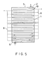
- Each of the openings is spaced annularly from said openings of two adjacent electrode plates at an angle of 180 degrees. Therefore, wastewater can be passed through the electrode plates from the bottom of the electrolytic cell to the top of the electrolytic cell.
- the flow path of the wastewater is Z-shaped in the electrolytic cell, so that said wastewater can contact the surfaces of the electrode plates evenly and thoroughly.
- the sweep of the scraper agitates wastewater, making the electrolytic treatment of wastewater more uniform.
- the electrolytic cell of the apparatus of this invention is formed with a plurality of stacked ring members.
- Each of the ring members has an inside diameter slightly smaller than the diameter of each of the circular electrode plates, so that each of said circular electrode Plates can be interposed between the two adjacent ring members at the periphery thereof.
- Sealing members are provided between the contact surfaces of the electrode plates and the ring members.
- the ring members are fastened to each other by the usual fasteners. In this way, the treatment capacity of the electrolytic cell can be changed as desired.
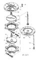
- an electrolytic apparatus for treating liquid media such as industrial wastewater and the like, includes an electrolytic cell 10 formed with a plurality of ring members 1 superimposed on each other.
- Each of the ring members 1 has a stepped inner periphery 11.
- Top and bottom sealing covers 5, 6 are respectively mounted to the topmost and bottommost ring members 1.
- the ring members 1 are preferably made of acrylonitrile butadiene styrene. Every two adjacent ring members 1 has a circular electrode plate 2 mounted therebetween.
- the electrode plates 2 are preferably made of iron as described in U.S. Patent Nos. 3926754, 4036726, 4123339, and European Patent Publication No. 0295696.
- Each of the electrode plates 2 has an opening 23 formed near the periphery thereof and a shank portion 21 radially extending from the outer periphery thereof.
- the electrode plates 2 are positioned between the stepped inner peripheries 11 of the ring members 1 and the top and bottom sealing covers 5, 6 in such a manner that each of the openings 23 is spaced annularly from the other said opening 23 of either one of two adjacent electrode plates 2 at an angle of 180 degrees.
- Seal rings 14 are provided between the contact surfaces of the electrode plates 2 and the inner peripheries 11 of the ring members 1 for sealing purposes, as best illustrated in Figs. 2A, 2B.
- a rotating shaft 7 is rotatably passed through the central portions of the ring members 1, the electrode plates 2 and the top and bottom sealing cover 5, 6.
- the rotating shaft 7 is connected to a driving shaft 91 which is driven by a motor 9 mounted above the top sealing cover 5.
- the top and bottom sealing covers 5, 6 and the ring members 1 are fastened together by means of fastening members such as nuts and threaded rods 71, 72, so that the electrode plates 2 can be sealingly positioned between the top and bottom sealing covers 5, 6 and the ring members 1 as described hereinbefore.
- the shank portions 21 of the electrode plates 2 are alternately connected to the positive poles 81 and the negative poles 82 of the bus boards 8, which are connected to a DC power supply for electrolytic treatment of wastewater.
- the top sealing cover 5 has an outlet opening 52 to which an outlet tube 54 is connected.
- the bottom cover 6 has an inlet opening 62 to which an inlet tube 64 is connected.
- a wheeled support 65 is mounted below the bottom sealing cover 6 to support the electrolytic apparatus of this invention.
- a liquid media such as industrial wastewater is passed upward into the electrolytic cell 10 of this invention from the inlet tube 64 and through the electrode plates 2 in a substantially Z-shaped path, as best illustrated in Fig. 5. After being electrochemically treated, wastewater flows out of the electrolytic cell 10 via the outlet tube 54.
- every two adjacent electrode plates 2 has a scraping member 3 mounted therebetween.
- the scraping member 3 includes a shank portion 31 connected to the rotating shaft 7 at one end thereof and a scraper 32 held by the shank portion 31.
- the scraper 32 of generally U-shaped cross section has two elastic blades 33 with two opposed bent edges 34.
- the blades 33 of the scraper 32 are substantially expended away from each other so that the bent edges 34 thereof can elastically abut upon the opposed surfaces of the adjacent electrode plates 2.
- the scraping member 3 can be rotated by the motor 9 about the rotating shaft 7, thereby sweeping over the opposed surfaces of the adjacent electrode plates 2, as shown in Fig.
- the scraper 32 is essentially made of polytetrafluoroethylene (Teflon) which is inherently anti-corrosive and elastic.
- Teflon polytetrafluoroethylene
- a crosslinking agent is added into the blades 33, so that polytetrafluoroethylene can be combined with the glass beads.
- the treated wastewater leaving the electrolytic apparatus of this invention may be collected in a tank to allow said treated wastewater to separate into a layer of precipitate or suspension mud and a layer of clear solution.
- the layer of precipitate or suspension mud may be separated from the layer of clear solution by a filtering device.
- the clear solution is then be passed through a sand filter for post treatment.
- the material of electrode plates of this invention may be varied according to the property of wastewater.
- the material is selected from iron, aluminium, iron alloy, aluminium alloy, iron-aluminium alloy, carbon steel and stainless steel.
- the scraping members 3 must be made of an insulated, anti-corrosive, material, heat-resistant, acid resistant, alkali resistant, and anti-deforming material, such as high performance plastic, e.g.
- the scraping members 3 is preferably made of polytetrafluoroethylene (Teflon).
Landscapes
- Chemical & Material Sciences (AREA)
- Chemical Kinetics & Catalysis (AREA)
- Electrochemistry (AREA)
- General Chemical & Material Sciences (AREA)
- Life Sciences & Earth Sciences (AREA)
- Hydrology & Water Resources (AREA)
- Engineering & Computer Science (AREA)
- Environmental & Geological Engineering (AREA)
- Water Supply & Treatment (AREA)
- Organic Chemistry (AREA)
- Water Treatment By Electricity Or Magnetism (AREA)
Priority Applications (2)
| Application Number | Priority Date | Filing Date | Title |
|---|---|---|---|
| CA002014112A CA2014112A1 (en) | 1990-04-06 | 1990-04-06 | Electrolytic apparatus for treating liquid media |
| EP90401062A EP0452597A1 (de) | 1990-04-19 | 1990-04-19 | Vorrichtung zur elektrolytischen Flüssigkeitsbehandlung |
Applications Claiming Priority (1)
| Application Number | Priority Date | Filing Date | Title |
|---|---|---|---|
| EP90401062A EP0452597A1 (de) | 1990-04-19 | 1990-04-19 | Vorrichtung zur elektrolytischen Flüssigkeitsbehandlung |
Publications (1)
| Publication Number | Publication Date |
|---|---|
| EP0452597A1 true EP0452597A1 (de) | 1991-10-23 |
Family
ID=8205703
Family Applications (1)
| Application Number | Title | Priority Date | Filing Date |
|---|---|---|---|
| EP90401062A Withdrawn EP0452597A1 (de) | 1990-04-06 | 1990-04-19 | Vorrichtung zur elektrolytischen Flüssigkeitsbehandlung |
Country Status (1)
| Country | Link |
|---|---|
| EP (1) | EP0452597A1 (de) |
Cited By (8)
| Publication number | Priority date | Publication date | Assignee | Title |
|---|---|---|---|---|
| DE4236723C1 (de) * | 1992-10-30 | 1994-04-28 | Wt Wassertechn Gmbh | Vorrichtung zur Reinigung und Aufbereitung von Schmutzwässern mittels Elektroflotation |
| DE4428787A1 (de) * | 1994-08-13 | 1996-02-15 | Fraunhofer Ges Forschung | Verfahren und Vorrichtung zum Reinigen von Abwasser |
| DE19541234A1 (de) * | 1995-11-06 | 1997-06-12 | Johannes Loch | Kalkauffängergerät KA Anwendung im Bereich Wassertechnik |
| DE19724005C1 (de) * | 1997-06-08 | 1999-07-29 | Hans Dr Ing Ritter | Elektrodenanordnung und Anoden-Schabvorrichtung zur Elektroflokkulation |
| ES2179722A1 (es) * | 1998-12-07 | 2003-01-16 | Integrated Pool Products Propr | Clorador de agua. |
| WO2011041658A1 (en) * | 2009-10-02 | 2011-04-07 | Bioionix, Inc. | Electrochemical liquid treatment cell with modular construction |
| CN109205869A (zh) * | 2018-10-25 | 2019-01-15 | 中科协创环境科技江苏有限公司 | 一种处理煤化工高浓度污水的净化装置 |
| CN113896287A (zh) * | 2021-11-05 | 2022-01-07 | 河北携海工程技术有限公司 | 自动除垢电化学水处理设备 |
Citations (3)
| Publication number | Priority date | Publication date | Assignee | Title |
|---|---|---|---|---|
| GB176457A (en) * | 1920-11-26 | 1922-02-27 | Arthur Dean Smith | Apparatus for treating liquids |
| EP0209603A1 (de) * | 1984-12-27 | 1987-01-28 | Osamu Mihara | Wasserreinigungsvorrichtung |
| US4668369A (en) * | 1986-06-26 | 1987-05-26 | King Arthur S | Reciprocating electrode cleaner for electric field liquid treater |
-
1990
- 1990-04-19 EP EP90401062A patent/EP0452597A1/de not_active Withdrawn
Patent Citations (3)
| Publication number | Priority date | Publication date | Assignee | Title |
|---|---|---|---|---|
| GB176457A (en) * | 1920-11-26 | 1922-02-27 | Arthur Dean Smith | Apparatus for treating liquids |
| EP0209603A1 (de) * | 1984-12-27 | 1987-01-28 | Osamu Mihara | Wasserreinigungsvorrichtung |
| US4668369A (en) * | 1986-06-26 | 1987-05-26 | King Arthur S | Reciprocating electrode cleaner for electric field liquid treater |
Cited By (10)
| Publication number | Priority date | Publication date | Assignee | Title |
|---|---|---|---|---|
| DE4236723C1 (de) * | 1992-10-30 | 1994-04-28 | Wt Wassertechn Gmbh | Vorrichtung zur Reinigung und Aufbereitung von Schmutzwässern mittels Elektroflotation |
| DE4428787A1 (de) * | 1994-08-13 | 1996-02-15 | Fraunhofer Ges Forschung | Verfahren und Vorrichtung zum Reinigen von Abwasser |
| US5587064A (en) * | 1994-08-13 | 1996-12-24 | Fraunhofer-Gesellschaft Zur Forderung Der Angewandten Forschung E.V. | Waste water purification process and apparatus |
| DE19541234A1 (de) * | 1995-11-06 | 1997-06-12 | Johannes Loch | Kalkauffängergerät KA Anwendung im Bereich Wassertechnik |
| DE19724005C1 (de) * | 1997-06-08 | 1999-07-29 | Hans Dr Ing Ritter | Elektrodenanordnung und Anoden-Schabvorrichtung zur Elektroflokkulation |
| ES2179722A1 (es) * | 1998-12-07 | 2003-01-16 | Integrated Pool Products Propr | Clorador de agua. |
| WO2011041658A1 (en) * | 2009-10-02 | 2011-04-07 | Bioionix, Inc. | Electrochemical liquid treatment cell with modular construction |
| US8961751B2 (en) | 2009-10-02 | 2015-02-24 | Biolonix, Inc. | Electrochemical liquid treatment cell with modular construction |
| CN109205869A (zh) * | 2018-10-25 | 2019-01-15 | 中科协创环境科技江苏有限公司 | 一种处理煤化工高浓度污水的净化装置 |
| CN113896287A (zh) * | 2021-11-05 | 2022-01-07 | 河北携海工程技术有限公司 | 自动除垢电化学水处理设备 |
Similar Documents
| Publication | Publication Date | Title |
|---|---|---|
| US5928493A (en) | Process and apparatus for electrocoagulative treatment of industrial waste water | |
| US7758742B2 (en) | Method and apparatus for separation of water from petroleum products in an electrocoagulation process | |
| US8048279B2 (en) | Method and apparatus for electrocoagulation of liquids | |
| US6294061B1 (en) | Process and apparatus for electrocoagulative treatment of industrial waste water | |
| US8500989B2 (en) | Turboelectric coagulation apparatus | |
| CN203498138U (zh) | 平行多级电化学水处理设备 | |
| AU2794299A (en) | Method and apparatus for electrocoagulation of liquids | |
| CN103466758B (zh) | 复合阴极以及采用这种阴极的电化学多级水处理设备 | |
| US4105534A (en) | Apparatus for removing impurities from electrolyte solutions | |
| CN1097653C (zh) | 具有电解污水处理装置的洗衣机 | |
| EP0452597A1 (de) | Vorrichtung zur elektrolytischen Flüssigkeitsbehandlung | |
| US6613202B2 (en) | Tank batch electrochemical water treatment process | |
| CN111704214A (zh) | 一种电化学污水处理系统 | |
| US6241861B1 (en) | Waste water treatment tank using an electrochemical treatment process | |
| US8877032B2 (en) | Generation of chemical reagents for various process functions utilizing an agitated liquid and electrically conductive environment and an electro chemical cell | |
| US4800005A (en) | Treatment plant for recovery of metal from hazardous waste | |
| US4206030A (en) | Electrode assembly | |
| CN210409734U (zh) | 一种工业废水处理的分离装置 | |
| CA2014112A1 (en) | Electrolytic apparatus for treating liquid media | |
| RU2029735C1 (ru) | Устройство для очистки сточных вод "ферроксер" | |
| KR200227263Y1 (ko) | 접촉면적을 극대화시킨 경사판침전조 | |
| SU1000406A1 (ru) | Электролизер дл очистки сточных вод | |
| CN1055527A (zh) | 水处理的电解装置 | |
| CN216997788U (zh) | 电絮凝沉淀设备 | |
| CN216677222U (zh) | 一种烟气脱硫废水回收压榨装置 |
Legal Events
| Date | Code | Title | Description |
|---|---|---|---|
| PUAI | Public reference made under article 153(3) epc to a published international application that has entered the european phase |
Free format text: ORIGINAL CODE: 0009012 |
|
| AK | Designated contracting states |
Kind code of ref document: A1 Designated state(s): AT BE CH DE DK ES FR GB GR IT LI LU NL SE |
|
| STAA | Information on the status of an ep patent application or granted ep patent |
Free format text: STATUS: THE APPLICATION IS DEEMED TO BE WITHDRAWN |
|
| 18D | Application deemed to be withdrawn |
Effective date: 19920424 |