EP0452601A1 - Buoyancy motor - Google Patents
Buoyancy motor Download PDFInfo
- Publication number
- EP0452601A1 EP0452601A1 EP90440070A EP90440070A EP0452601A1 EP 0452601 A1 EP0452601 A1 EP 0452601A1 EP 90440070 A EP90440070 A EP 90440070A EP 90440070 A EP90440070 A EP 90440070A EP 0452601 A1 EP0452601 A1 EP 0452601A1
- Authority
- EP
- European Patent Office
- Prior art keywords
- motor according
- motor
- sequence
- gas
- thrust
- Prior art date
- Legal status (The legal status is an assumption and is not a legal conclusion. Google has not performed a legal analysis and makes no representation as to the accuracy of the status listed.)
- Withdrawn
Links
- 238000007654 immersion Methods 0.000 claims description 15
- 238000004891 communication Methods 0.000 claims description 9
- 239000012530 fluid Substances 0.000 claims description 7
- 230000006835 compression Effects 0.000 claims description 5
- 238000007906 compression Methods 0.000 claims description 5
- 239000007788 liquid Substances 0.000 claims description 4
- 230000001174 ascending effect Effects 0.000 claims description 3
- 238000000605 extraction Methods 0.000 claims description 2
- 230000001105 regulatory effect Effects 0.000 claims 2
- 238000005265 energy consumption Methods 0.000 abstract description 2
- 230000007246 mechanism Effects 0.000 description 5
- 238000004064 recycling Methods 0.000 description 3
- 230000015556 catabolic process Effects 0.000 description 1
- 238000010276 construction Methods 0.000 description 1
- 230000003247 decreasing effect Effects 0.000 description 1
- 238000006073 displacement reaction Methods 0.000 description 1
- 230000000694 effects Effects 0.000 description 1
- 238000007667 floating Methods 0.000 description 1
- 238000012423 maintenance Methods 0.000 description 1
- 239000002184 metal Substances 0.000 description 1
- 230000004048 modification Effects 0.000 description 1
- 238000012986 modification Methods 0.000 description 1
- XLYOFNOQVPJJNP-UHFFFAOYSA-N water Substances O XLYOFNOQVPJJNP-UHFFFAOYSA-N 0.000 description 1
- 238000004804 winding Methods 0.000 description 1
Images

Classifications
-
- F—MECHANICAL ENGINEERING; LIGHTING; HEATING; WEAPONS; BLASTING
- F03—MACHINES OR ENGINES FOR LIQUIDS; WIND, SPRING, OR WEIGHT MOTORS; PRODUCING MECHANICAL POWER OR A REACTIVE PROPULSIVE THRUST, NOT OTHERWISE PROVIDED FOR
- F03B—MACHINES OR ENGINES FOR LIQUIDS
- F03B17/00—Other machines or engines
- F03B17/02—Other machines or engines using hydrostatic thrust
- F03B17/04—Alleged perpetua mobilia
Definitions
- the present invention relates to the field of motors comprising drive systems such that the energy consumption necessary to drive these motors is extremely low.
- Such motors are frequently qualified, obviously wrongly, by the expression "perpetual movement” and generally include purely mechanical systems, for example using mechanisms involving levers whose arm length is modified due to a modification or a breakdown of balance occurring "spontaneously” and therefore absorbing only insignificant energy.
- the motive energy which drives the engine results from the Archimedes push which is exerted on volumes whose displacement determines the setting and the maintenance in rotation of the motor shaft of the motor.
- said Archimedes thrust is exerted differently on two series of elements joined together so as to form an endless sequence and made up of variable volumes in which is gas pressure kept constant, at least the elements of this sequence having the largest volume being immersed in a fluid from which they receive the buoyancy.
- the entire chain is placed in a mass of a fluid so that, the enclosures whose volume is the largest undergoing from this fluid an Archimedes push larger than the speakers whose volume is lower, the imbalance resulting from this difference in thrust determines an upward scrolling of the sequence on the side of the speakers whose volume is greater and descending on the other side, this scrolling determining itself -even the rotation of the motor shaft of the motor.
- the gas pressure is kept constant in the deformable enclosures by introducing gas into the lower elements of the ascending portion and gas extraction in the upper elements of the descending portion.
- this recycling is done by successively placing all the pairs of speakers in communication by means of a communication system by valves arranged at the two ends of a common pipe.
- each pair of speakers is equipped with a pipe keeping them permanently in communication, therefore under constant gas pressure, the total amount of gas in each pair remaining constant, but its distribution determining the inflation of the ascending speakers and deflating the descending chambers.
- this motor can operate on demand, at any speed driving the shaft around which the chain of speakers is wound.
- the operating speed of the engine obviously depends on the speed at which the transfer of air takes place from the upper enclosure by a torque to the lower enclosure.
- the construction of the engine according to the invention must make use of a certain number of feasibility criteria.
- the enclosures being of variable volume, said enclosures comprise at least one movable wall whose position determines the volume, the enclosure remaining sealed regardless of this position.
- said movable walls can be made of metal coated with plastic and joined by a plastic bellows.
- the succession of enclosures forming the chain is connected practically without play by hinges serving at the same time as support for the winding of the chain on the motor shaft.
- the immersion tank 1 is integral with a rotary mechanism so as to prevent it from floating, which comprises two cheek wheels, one high 2, the other low 2 ', linked together by an endless chain constituted by floats 3 to 3/21 hinged together.
- the floats in position 3/12 to 3/21 are contracted, in order to be submerged in their smallest volume during the rotation of the assembly, in order to undergo, the buoyancy of Archimedes contrary to the movement, the most weak possible.
- the floats are expanded under the internal pressure of a gas, at least equal to the immersion pressure at the lowest point.
- the floats have been provided having two rigid horizontal faces, while the lateral faces are constituted by articulated bellows, so as to allow their compression and expansion.
- the expansion gas is introduced into the floats in 3 to 3/2 through the valves 6 '; this gas came from compression, between the positions 3/10 and 3/12 of the floats passing under the cam 7.
- This gas circulating through the system 5, which being fixed, has cheeks of sealed rotations with the rotary carrier drums valves 6 and 6 '.
- the floats 3 to 3/21 have the particularity of not being able to expand beyond the volume reached in position 3/2, in order to keep the internal pressure constant between 3 and 3/12.
- the Archimedes 'thrust generates a torque on the axis of the wheel 2', a torque which will increase during the rotation towards 3 / 2.
- the rotating assembly will be unbalanced to move in the direction of the arrow, which represents the dominant Archimedes' thrust.
- This thrust will be maximum and constant on the floats in positions 3/2 to 3/9; it will decrease in 3/10, depending on the gradual emergence of the float. It will increase between 3 and 3/2 as the float expands.
- the elements of the system are: For a chain made up of 26 floats. 200 liters float jacket, weight 100 kgs. Floats dilated by 1000 liters of compressed air.
Landscapes
- Engineering & Computer Science (AREA)
- Chemical & Material Sciences (AREA)
- Combustion & Propulsion (AREA)
- Mechanical Engineering (AREA)
- General Engineering & Computer Science (AREA)
- Other Liquid Machine Or Engine Such As Wave Power Use (AREA)
Abstract
Description
La présente invention concerne le domaine des moteurs comportant des systèmes d'entraînement tels que la consommation en énergie nécessaire pour animer ces moteurs est extrêmement faible. De tels moteurs sont fréquemment qualifiés, évidemment à tort, par l'expression "mouvement perpétuel" et comportent généralement des systèmes purement mécaniques, faisant par exemple appel à des mécanismes impliquant des leviers dont la longueur des bras est modifiée en raison d'une modification ou d'une rupture d'équilibre intervenant "spontanément" et n'absorbant donc qu'une énergie insignifiante.The present invention relates to the field of motors comprising drive systems such that the energy consumption necessary to drive these motors is extremely low. Such motors are frequently qualified, obviously wrongly, by the expression "perpetual movement" and generally include purely mechanical systems, for example using mechanisms involving levers whose arm length is modified due to a modification or a breakdown of balance occurring "spontaneously" and therefore absorbing only insignificant energy.
L'originalité du moteur selon la présente invention réside dans le fait que ledit système d'entraînement n'est pas purement mécanique, mais essentiellement physique, faisant appel à l'application de la poussée d'Archimède.The originality of the engine according to the present invention lies in the fact that said drive system is not purely mechanical, but essentially physical, calling upon the application of Archimedes' thrust.
En d'autres termes, dans le moteur selon la présente invention, l'énergie motrice qui anime le moteur résulte de la poussée d'Archimède qui s'exerce sur des volumes dont le déplacement détermine la mise et le maintien en rotation de l'arbre moteur du moteur.In other words, in the engine according to the present invention, the motive energy which drives the engine results from the Archimedes push which is exerted on volumes whose displacement determines the setting and the maintenance in rotation of the motor shaft of the motor.
Plus particulièrement, dans le moteur selon l'invention, ladite poussée d'Archimède s'exerce différentiellement sur deux séries d'éléments réunis ensemble de manière à former un enchaînement sans fin et constitués de volumes variables dans lesquels est maintenue constante une pression gazeuse, au moins les éléments de cet enchaînement ayant le plus grand volume étant immergés dans un fluide dont ils reçoivent la poussée d'Archimède.More particularly, in the engine according to the invention, said Archimedes thrust is exerted differently on two series of elements joined together so as to form an endless sequence and made up of variable volumes in which is gas pressure kept constant, at least the elements of this sequence having the largest volume being immersed in a fluid from which they receive the buoyancy.
Selon une réalisation préférentielle de l'invention, la totalité de l'enchaînement est placée dans une masse d'un fluide de manière telle que, les enceintes dont le volume est le plus grand subissant de la part de ce fluide une poussée d'Archimède plus importante que les enceintes dont le volume est plus faible, le déséquilibre résultant de cette différence de poussée détermine un défilement ascendant de l'enchaînement du côté des enceintes dont le volume est plus grand et descendant de l'autre côté, ce défilement déterminant lui-même la mise en rotation de l'arbre moteur du moteur.According to a preferred embodiment of the invention, the entire chain is placed in a mass of a fluid so that, the enclosures whose volume is the largest undergoing from this fluid an Archimedes push larger than the speakers whose volume is lower, the imbalance resulting from this difference in thrust determines an upward scrolling of the sequence on the side of the speakers whose volume is greater and descending on the other side, this scrolling determining itself -even the rotation of the motor shaft of the motor.
Dans la pratique, la pression du gaz est maintenue constante dans les enceintes déformables par introduction de gaz dans les éléments inférieurs de la portion ascendante et extraction de gaz dans les éléments supérieurs de la portion descendante.In practice, the gas pressure is kept constant in the deformable enclosures by introducing gas into the lower elements of the ascending portion and gas extraction in the upper elements of the descending portion.
En fait, il s'agit donc là d'un recyclage permanent du gaz de chaque élément supérieur à l'élément inférieur correspondant, un tel recyclage ne faisant intervenir qu'un apport d'énergie extérieure extrêmement faible.In fact, this is therefore a permanent recycling of the gas from each upper element to the corresponding lower element, such recycling involving only an extremely low external energy supply.
Selon une première variante de l'invention, ce recyclage se fait par mise en communication successivement de tous les couples d'enceintes au moyen d'un système de mise en communication par des valves disposées aux deux extrémités d'une canalisation commune.According to a first variant of the invention, this recycling is done by successively placing all the pairs of speakers in communication by means of a communication system by valves arranged at the two ends of a common pipe.
Selon une seconde variante, chaque couple d'enceintes est équipé d'un tuyau les conservant en permanence en communication, donc sous pression de gaz constante, la quantité totale de gaz dans chaque couple demeurant constante, mais sa répartition déterminant le gonflage des enceintes ascendantes et le dégonflage des enceintes descendantes.According to a second variant, each pair of speakers is equipped with a pipe keeping them permanently in communication, therefore under constant gas pressure, the total amount of gas in each pair remaining constant, but its distribution determining the inflation of the ascending speakers and deflating the descending chambers.
Cela étant posé, il apparaît que, malgré son extrême simplicité, ce moteur peut fonctionner à la demande, à toute vitesse d'entraînement de l'arbre autour duquel s'enroule l'enchaînement d'enceintes.That being said, it appears that, despite its extreme simplicity, this motor can operate on demand, at any speed driving the shaft around which the chain of speakers is wound.
La vitesse de fonctionnement du moteur dépend évidemment de la vitesse à laquelle s'opère le transfert d'air de l'enceinte supérieure d'un couple à l'enceinte inférieure. On peut également intervenir sur cette vitesse en modifiant le degré d'immersion du système, soit en agissant sur le niveau du liquide, soit en agissant sur la profondeur d'immersion du système.The operating speed of the engine obviously depends on the speed at which the transfer of air takes place from the upper enclosure by a torque to the lower enclosure. One can also intervene on this speed by modifying the degree of immersion of the system, either by acting on the level of the liquid, or by acting on the depth of immersion of the system.
La construction du moteur selon l'invention doit faire appel à un certain nombre de critères de faisabilité.The construction of the engine according to the invention must make use of a certain number of feasibility criteria.
Ainsi, les enceintes étant à volume variable, lesdites enceintes comportent au moins une paroi mobile dont la position détermine le volume, l'enceinte demeurant étanche quelle que soit cette position.Thus, the enclosures being of variable volume, said enclosures comprise at least one movable wall whose position determines the volume, the enclosure remaining sealed regardless of this position.
Par exemple, lesdites parois mobiles peuvent être en métal enrobé de plastique et réunies par un soufflet en plastique.For example, said movable walls can be made of metal coated with plastic and joined by a plastic bellows.
La succession d'enceintes formant l'enchaînement est reliée pratiquement sans jeu par des charnières servant en même temps d'appui pour l'enroulement de l'enchaînement sur l'arbre moteur.The succession of enclosures forming the chain is connected practically without play by hinges serving at the same time as support for the winding of the chain on the motor shaft.
A titre d'exemple, on va décrire ci-après un mode de réalisation de l'invention, en se référant au dessin annexé représentant très schématiquement le système.By way of example, an embodiment of the invention will be described below, with reference to the appended drawing very schematically showing the system.
Sur ce dessin, les références numériques désignent :
- 1 :
- réservoir d'immersion du mécanisme rotatif,
- 2:
- roue haute du mécanisme et son axe de rotation,
- 2' :
- roue basse du mécanisme et son axe de rotation,
3à 3/21 :- flotteurs articulés entre eux, formant chaîne sans fin,
- 4 :
- niveau haut du liquide d'immersion,
- 5 :
- système de transfert du gaz entre flotteurs,
- 6 et 6':
- valves ordinatrices du transfert du gaz,
- 7 :
- came de compression des flotteurs émergés,
- 8 :
- réserve de gaz comprimé de démarrage ou de secours,
- 9 :
- came de dilatation des flotteurs.
- 1:
- immersion tank of the rotary mechanism,
- 2:
- high wheel of the mechanism and its axis of rotation,
- 2 ':
- low wheel of the mechanism and its axis of rotation,
- 3 to 3/21:
- floats hinged together, forming an endless chain,
- 4:
- high level of immersion liquid,
- 5:
- gas transfer system between floats,
- 6 and 6 ':
- computer gas transfer valves,
- 7:
- compression cam for emerged floats,
- 8:
- reserve of compressed starting or emergency gas,
- 9:
- float expansion cam.
Le réservoir d'immersion 1 est solidaire d'un mécanisme rotatif de manière à l'empêcher de flotter, lequel comporte deux roues à joues, l'une haute 2, l'autre basse 2', reliées entre elles par une chaîne sans fin constituée par des flotteurs 3 à 3/21 articulés entre eux.The
Les flotteurs en position 3/12 à 3/21 sont contractés, afin d'être immergés sous leur plus faible volume au cours de la rotation de l'ensemble, afin de subir à, la poussée d'Archimède contraire au mouvement, la plus faible possible.The floats in
De 3 à 3/9 les flotteurs sont dilatés sous la pression interne d'un gaz, au moins égale à la pression d'immersion au point le plus bas.From 3 to 3/9 the floats are expanded under the internal pressure of a gas, at least equal to the immersion pressure at the lowest point.
Les flotteurs ont été prévus ayant deux faces horizontales rigides, tandis que les faces latérales sont constituées par des soufflets articulés, de manière à permettre leur compression et dilatation.The floats have been provided having two rigid horizontal faces, while the lateral faces are constituted by articulated bellows, so as to allow their compression and expansion.
En fonctionnement normal, le gaz de dilatation est introduit dans les flotteurs en 3 à 3/2 par les valves 6'; ce gaz est venu de la compression, entre les positions 3/10 et 3/12 des flotteurs passant sous la came 7. Ce gaz circulant à travers le système 5, lequel étant fixe, possède des joues de rotations étanches avec les tambours rotatifs porteurs des valves 6 et 6'.In normal operation, the expansion gas is introduced into the floats in 3 to 3/2 through the valves 6 '; this gas came from compression, between the
Les flotteurs 3 à 3/21 présentent la particularité de ne pouvoir se dilater au delà du volume atteint en position 3/2, afin de maintenir constante la pression interne entre 3 et 3/12.The
Sous l'effet de la came 9 qui guide ou aide à la déformation du flotteur en 3, la poussée d'Archimède génère un couple sur l'axe de la roue 2', couple qui ira croissant au cours de la rotation vers 3/2. Rapidement l'ensemble rotatif sera déséquilibré pour se mouvoir en direction de la flèche, laquelle figure la poussée d'Archimède dominante. Cette poussée sera maximale et constante sur les flotteurs en positions 3/2 à 3/9 ; elle sera décroissante en 3/10, en fonction de l'émersion progressive du flotteur. Elle sera croissante entre 3 et 3/2 au fur et à mesure que se dilatera le flotteur.Under the effect of the
Dès que le flotteur parvient en position 3/10, la communication avec celui qui se trouve en position 3 s'établit à l'intervention de l'ouverture simultanée des valves 6 et 6' via le système de communication 5 et jusqu'à l'arrivée aux positions 3/2 d'une part et 3/12 d'autre part. Cette mise en communication s'effectue simultanément à l'action de la came 7, dont la poussée mécanique comprimant le flotteur entre les positions 3/10 à 3/12 exprimera vers 3 à 3/2 son contenu gazeux, un complément éventuel de travail étant prélevé sur la rotation de la chaîne, afin de compenser les pertes de charges du transfert.As soon as the float reaches
Pour que le système fonctionne en continu et soit efficient, il importe évidemment que le travail nécessaire au transfert du gaz soit moins important que celui qui est fourni par l'immersion des flotteurs entre 3 et 3/10.For the system to operate continuously and to be efficient, it is obviously important that the work necessary to transfer the gas is less important than that which is provided by the immersion of the floats between 3 and 3/10.
L'on constate que la mise en communication de 3/10 et 3 ni le volume, ni la pression ne subissent aucun changement, la détente du gaz au fur et à mesure que diminuait la pression d'immersion ayant été empêchée grâce au maintien constant du volume des flotteurs entre 3/2 et 3/9. Il découle de cela qu'il suffira de fournir au système pour qu'il fonctionne, l'équivalent des pertes de charges en 6,6' et 5 ainsi que du roulement de l'ensemble.It can be seen that the connection of 3/10 and 3 neither the volume nor the pressure undergo any change, the expansion of the gas as the immersion pressure decreased having been prevented by maintaining constant of the volume of the floats between 3/2 and 3/9. It follows from this that it will suffice to provide the system for it to function, the equivalent of the pressure drops in 6.6 'and 5 as well as the bearing of the assembly.
Si contrairement le volume et la pression avaient varié, le fait aurait entraîné une dépense d'énergie de recompression du gaz inutile et nuisible.If, on the contrary, the volume and the pressure had varied, the fact would have led to an unnecessary and harmful expenditure of energy for recompression of the gas.
De même, au cas de transfert pneumatique du gaz, il suffira d'augmenter la pression d'admission au compresseur de l'équivalent des mêmes pertes de charges du transfert et de roulement.Likewise, in the case of pneumatic transfer of the gas, it will suffice to increase the inlet pressure to the compressor by the equivalent of the same pressure losses of the transfer and of the bearing.
Il apparaît donc que l'émersion des flotteurs dilatés est motrice de l'ensemble tournant. L'action sera continue, chaque flotteur parvenant en position 3 générant une nouvelle poussée d'Archimède motrice.It therefore appears that the emergence of the expanded floats is the driving force behind the rotating assembly. The action will be continuous, each float arriving in
A titre d'exemple également, on donne ci-après, un calcul approximatif des conditions de fonctionnement du système qui vient d'être décrit, dans lequel le gaz est l'air, et le fluide d'immersion est l'eau.Also by way of example, an approximate calculation of the operating conditions of the system which has just been described is given below, in which the gas is air, and the immersion fluid is water.
Les éléments du système sont :
Pour une chaîne constituée de 26 flotteurs.
Enveloppe des flotteurs 200 litres, poids 100 kgs.
Flotteurs dilatés par 1000 litres d'air pressé.
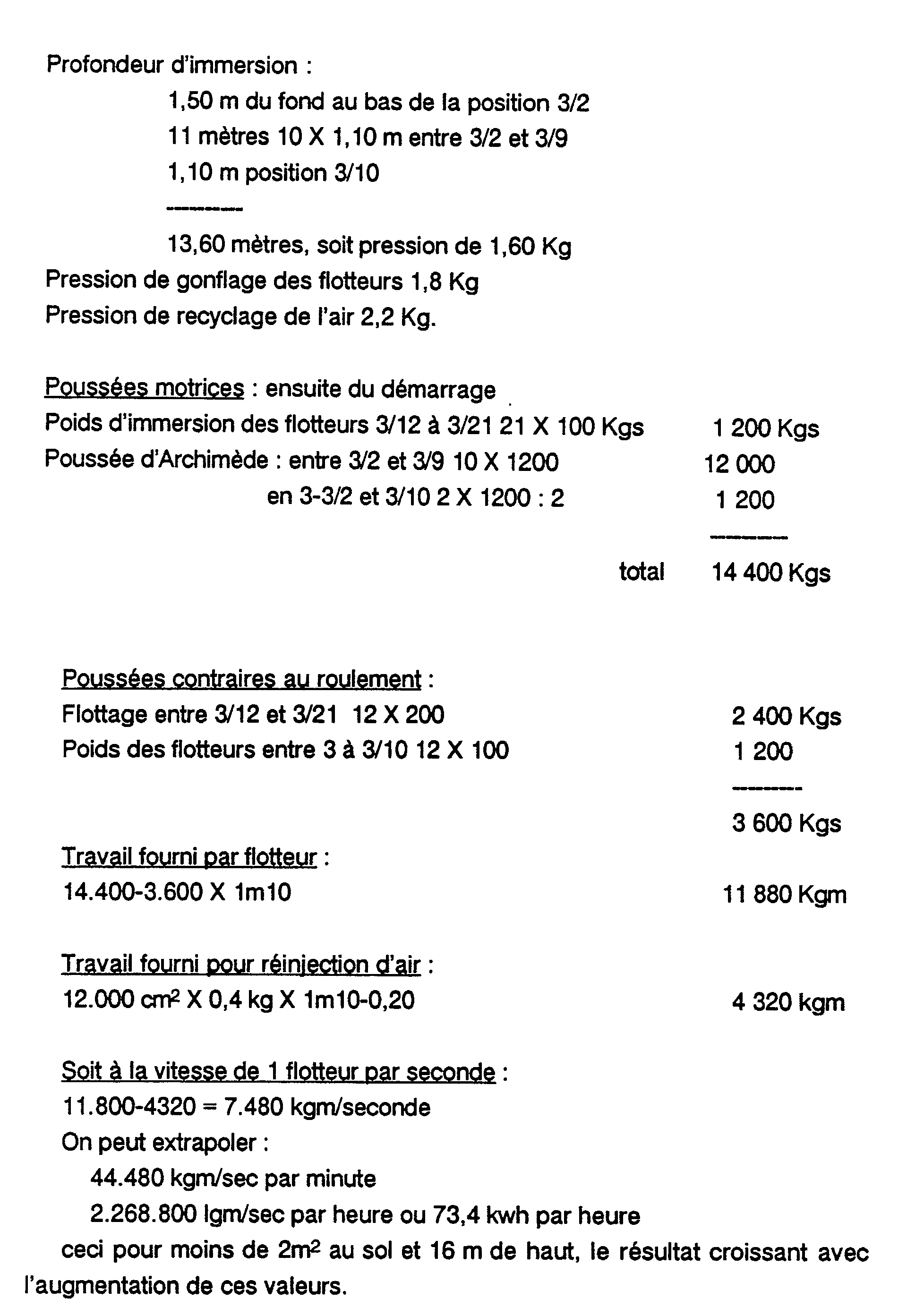
For a chain made up of 26 floats.
200 liters float jacket, weight 100 kgs.
Floats dilated by 1000 liters of compressed air.
Bien entendu, il s'agit là d'un simple exemple illustratif, et de très nombreuses variantes pourront en être réalisées, en restant dans le cadre des revendications ci-après.Of course, this is a simple illustrative example, and many variations can be made, remaining within the scope of the claims below.
Claims (15)
Applications Claiming Priority (1)
| Application Number | Priority Date | Filing Date | Title |
|---|---|---|---|
| MC2126A MC2198A1 (en) | 1990-04-20 | 1990-04-20 | Hydraulic motor using Archimedes' thrust |
Publications (1)
| Publication Number | Publication Date |
|---|---|
| EP0452601A1 true EP0452601A1 (en) | 1991-10-23 |
Family
ID=19738215
Family Applications (1)
| Application Number | Title | Priority Date | Filing Date |
|---|---|---|---|
| EP90440070A Withdrawn EP0452601A1 (en) | 1990-04-20 | 1990-07-31 | Buoyancy motor |
Country Status (2)
| Country | Link |
|---|---|
| EP (1) | EP0452601A1 (en) |
| MC (2) | MC2198A1 (en) |
Cited By (13)
| Publication number | Priority date | Publication date | Assignee | Title |
|---|---|---|---|---|
| ES2079302A2 (en) * | 1993-10-19 | 1996-01-01 | Santana Jose Perez | Scoop wheel for still (standing, resting) waters |
| WO1998053199A1 (en) * | 1997-09-25 | 1998-11-26 | Stabek Miroslav | Buoyancy motor |
| ES2153746A1 (en) * | 1994-05-23 | 2001-03-01 | Garcia Alejandro Aparicio | System for raising water without the consumption of energy and production of energy in closed circuit |
| GB2385384A (en) * | 2002-02-13 | 2003-08-20 | Daniel Millen | Float powered rotary wheel |
| RU2214531C1 (en) * | 2003-01-17 | 2003-10-20 | Джанибеков Владимир Александрович | Pneumohydraulic converter of mechanical energy into electric energy |
| RU2215183C2 (en) * | 2001-04-10 | 2003-10-27 | Темников Алексей Витальевич | Low-pressure steam or air energy converter |
| EP1452732A1 (en) * | 2003-02-28 | 2004-09-01 | Chien-Hua Huang | Hydraulic buoyant force engine |
| WO2007076719A1 (en) * | 2005-12-31 | 2007-07-12 | Solar City Limited | A power output device and a generating device using the same |
| US20170306920A1 (en) * | 2015-01-14 | 2017-10-26 | Ngoc Quy Pham | The engine operated by the buoyancy of water |
| ES2699435A1 (en) * | 2017-09-05 | 2019-02-11 | Eventos Andalucia 2020 S L | Closed and autonomous circuit with currents and internal flows of fluids and bodies by Archimedes push with magnetic reinforcement for generation of mechanical and electrical energy and operating procedure (Machine-translation by Google Translate, not legally binding) |
| CN112796929A (en) * | 2021-01-29 | 2021-05-14 | 嘉兴大道锻造技术咨询有限公司 | A buoyancy energy conversion device |
| DE102021003913A1 (en) | 2021-07-29 | 2023-02-02 | Robert Odenbach | Density body-2 |
| WO2023115186A1 (en) * | 2021-12-21 | 2023-06-29 | Rafael Camilotti | Submerged system for producing thrust for energy generation |
Citations (5)
| Publication number | Priority date | Publication date | Assignee | Title |
|---|---|---|---|---|
| GB191311516A (en) * | 1913-05-17 | 1914-05-14 | Georges Justin Joseph Legrand | An Improved Hydro-atmospheric Motor for Weight Displacement. |
| FR1093161A (en) * | 1954-02-04 | 1955-05-02 | Energy machine with hydraulic pressure | |
| FR2442352A1 (en) * | 1978-11-23 | 1980-06-20 | Briot Yves | Turbine for hydroelectric installation - employs series of weights attached to bellows which compress in water to lose mass |
| FR2502254A1 (en) * | 1980-12-09 | 1982-09-24 | Philadelphe Gerard | Immersed perpetual motion machine - has frame with belt carrying selectively deflated floats to drive it |
| EP0262645A1 (en) * | 1986-09-29 | 1988-04-06 | Radomir Dipl.-Ing. Cvijovic | A hydrothrusting turbine |
-
1990
- 1990-04-20 MC MC2126A patent/MC2198A1/en unknown
- 1990-06-26 MC MC2126K patent/MC215A7/en unknown
- 1990-07-31 EP EP90440070A patent/EP0452601A1/en not_active Withdrawn
Patent Citations (5)
| Publication number | Priority date | Publication date | Assignee | Title |
|---|---|---|---|---|
| GB191311516A (en) * | 1913-05-17 | 1914-05-14 | Georges Justin Joseph Legrand | An Improved Hydro-atmospheric Motor for Weight Displacement. |
| FR1093161A (en) * | 1954-02-04 | 1955-05-02 | Energy machine with hydraulic pressure | |
| FR2442352A1 (en) * | 1978-11-23 | 1980-06-20 | Briot Yves | Turbine for hydroelectric installation - employs series of weights attached to bellows which compress in water to lose mass |
| FR2502254A1 (en) * | 1980-12-09 | 1982-09-24 | Philadelphe Gerard | Immersed perpetual motion machine - has frame with belt carrying selectively deflated floats to drive it |
| EP0262645A1 (en) * | 1986-09-29 | 1988-04-06 | Radomir Dipl.-Ing. Cvijovic | A hydrothrusting turbine |
Cited By (15)
| Publication number | Priority date | Publication date | Assignee | Title |
|---|---|---|---|---|
| ES2079302A2 (en) * | 1993-10-19 | 1996-01-01 | Santana Jose Perez | Scoop wheel for still (standing, resting) waters |
| ES2153746A1 (en) * | 1994-05-23 | 2001-03-01 | Garcia Alejandro Aparicio | System for raising water without the consumption of energy and production of energy in closed circuit |
| WO1998053199A1 (en) * | 1997-09-25 | 1998-11-26 | Stabek Miroslav | Buoyancy motor |
| AU738335B2 (en) * | 1997-09-25 | 2001-09-13 | Miroslav Stabek | Buoyancy motor |
| RU2215183C2 (en) * | 2001-04-10 | 2003-10-27 | Темников Алексей Витальевич | Low-pressure steam or air energy converter |
| GB2385384A (en) * | 2002-02-13 | 2003-08-20 | Daniel Millen | Float powered rotary wheel |
| GB2385384B (en) * | 2002-02-13 | 2004-03-31 | Daniel Millen | Hydro Electric Scheme Using Flotation Power |
| RU2214531C1 (en) * | 2003-01-17 | 2003-10-20 | Джанибеков Владимир Александрович | Pneumohydraulic converter of mechanical energy into electric energy |
| EP1452732A1 (en) * | 2003-02-28 | 2004-09-01 | Chien-Hua Huang | Hydraulic buoyant force engine |
| WO2007076719A1 (en) * | 2005-12-31 | 2007-07-12 | Solar City Limited | A power output device and a generating device using the same |
| US20170306920A1 (en) * | 2015-01-14 | 2017-10-26 | Ngoc Quy Pham | The engine operated by the buoyancy of water |
| ES2699435A1 (en) * | 2017-09-05 | 2019-02-11 | Eventos Andalucia 2020 S L | Closed and autonomous circuit with currents and internal flows of fluids and bodies by Archimedes push with magnetic reinforcement for generation of mechanical and electrical energy and operating procedure (Machine-translation by Google Translate, not legally binding) |
| CN112796929A (en) * | 2021-01-29 | 2021-05-14 | 嘉兴大道锻造技术咨询有限公司 | A buoyancy energy conversion device |
| DE102021003913A1 (en) | 2021-07-29 | 2023-02-02 | Robert Odenbach | Density body-2 |
| WO2023115186A1 (en) * | 2021-12-21 | 2023-06-29 | Rafael Camilotti | Submerged system for producing thrust for energy generation |
Also Published As
| Publication number | Publication date |
|---|---|
| MC215A7 (en) | 1992-10-05 |
| MC2198A1 (en) | 1992-10-05 |
Similar Documents
| Publication | Publication Date | Title |
|---|---|---|
| EP0452601A1 (en) | Buoyancy motor | |
| CN1172909A (en) | screw gas compressor | |
| FR2567967A1 (en) | DEVICE FOR EXTRACTING WAVE ENERGY IN A VOLUME OF LIQUID | |
| FR2948423A1 (en) | HYDROLIENNE MODULAR | |
| FR2640698A1 (en) | Peristaltic pump | |
| AU2011201378A1 (en) | Display mechanism illustrating fluid dynamics | |
| EP0728255A1 (en) | Control flask for polyphasic effluents and extraction assembly therefor | |
| FR2943741A1 (en) | Unit for transforming gravitational energy and Archimedes thrust into e.g. electric power, for use in power generation station, has tanks, where fluid is evacuated from one of tanks by injecting another fluid under pressure in other tank | |
| EP3209881B1 (en) | Water turbine, sliding lock gate including the same and process to convert hydraulic energy into electricity using them. | |
| WO2023194666A1 (en) | Device for generating a fluid flow, having a membrane | |
| BE1001619A3 (en) | Adjustable screw compressor. | |
| EP0069604A1 (en) | Hydraulic pumps or motors with helicoidal gears (screw turbines) | |
| WO2022100810A1 (en) | Compressed-air engine with integrated active chamber and active distribution with balanced valve | |
| EP3596335B1 (en) | Device for producing hydro-electric power | |
| EP2334906A1 (en) | Multifunction rotary machine with deformable rhomb | |
| WO2013098494A1 (en) | Hydraulic turbine intended, in particular, for a tidal power plant | |
| EP0246963A1 (en) | Recovering device for floating pollutants | |
| EP4522847B1 (en) | Compressed-air engine comprising an integrated active chamber and with active distribution and comprising a balanced exhaust valve for cylinder deactivation | |
| BE1013747A3 (en) | Device for creating a movement in a liquid | |
| FR2699967A1 (en) | Vane pump. | |
| FR2827917A1 (en) | Continuously-operating motor has bodies connected to endless chain or belt dropping through air-filled column and rising in water-filled column | |
| RU2080485C1 (en) | Gravitational vacuum-hydraulic motor | |
| FR2475146A1 (en) | Buoyancy supported wave power device - has reaction element with plate or membrane moving under action of wave forces converted into electrical generation | |
| EP3194763B1 (en) | Energy generation on a structure subject to swell | |
| BE1020282A5 (en) | TURBINE WITH VARIABLE ROTOR. |
Legal Events
| Date | Code | Title | Description |
|---|---|---|---|
| PUAI | Public reference made under article 153(3) epc to a published international application that has entered the european phase |
Free format text: ORIGINAL CODE: 0009012 |
|
| AK | Designated contracting states |
Kind code of ref document: A1 Designated state(s): AT BE CH DE DK ES FR GB GR IT LI LU NL SE |
|
| STAA | Information on the status of an ep patent application or granted ep patent |
Free format text: STATUS: THE APPLICATION IS DEEMED TO BE WITHDRAWN |
|
| 18D | Application deemed to be withdrawn |
Effective date: 19920425 |