EP0452625A1 - Fixation réglable d'une rotule sur une barre pour une timonerie de direction de véhicules automobiles - Google Patents
Fixation réglable d'une rotule sur une barre pour une timonerie de direction de véhicules automobiles Download PDFInfo
- Publication number
- EP0452625A1 EP0452625A1 EP91101982A EP91101982A EP0452625A1 EP 0452625 A1 EP0452625 A1 EP 0452625A1 EP 91101982 A EP91101982 A EP 91101982A EP 91101982 A EP91101982 A EP 91101982A EP 0452625 A1 EP0452625 A1 EP 0452625A1
- Authority
- EP
- European Patent Office
- Prior art keywords
- fastening
- screw
- axis
- bearing bore
- fixing
- Prior art date
- Legal status (The legal status is an assumption and is not a legal conclusion. Google has not performed a legal analysis and makes no representation as to the accuracy of the status listed.)
- Granted
Links
- 102000004315 Forkhead Transcription Factors Human genes 0.000 description 6
- 108090000852 Forkhead Transcription Factors Proteins 0.000 description 6
- 239000002184 metal Substances 0.000 description 1
- 238000012986 modification Methods 0.000 description 1
- 230000004048 modification Effects 0.000 description 1
Images

Classifications
-
- B—PERFORMING OPERATIONS; TRANSPORTING
- B62—LAND VEHICLES FOR TRAVELLING OTHERWISE THAN ON RAILS
- B62D—MOTOR VEHICLES; TRAILERS
- B62D7/00—Steering linkage; Stub axles or their mountings
- B62D7/16—Arrangement of linkage connections
-
- Y—GENERAL TAGGING OF NEW TECHNOLOGICAL DEVELOPMENTS; GENERAL TAGGING OF CROSS-SECTIONAL TECHNOLOGIES SPANNING OVER SEVERAL SECTIONS OF THE IPC; TECHNICAL SUBJECTS COVERED BY FORMER USPC CROSS-REFERENCE ART COLLECTIONS [XRACs] AND DIGESTS
- Y10—TECHNICAL SUBJECTS COVERED BY FORMER USPC
- Y10T—TECHNICAL SUBJECTS COVERED BY FORMER US CLASSIFICATION
- Y10T403/00—Joints and connections
- Y10T403/32—Articulated members
- Y10T403/32114—Articulated members including static joint
- Y10T403/32188—Angled or offset members
-
- Y—GENERAL TAGGING OF NEW TECHNOLOGICAL DEVELOPMENTS; GENERAL TAGGING OF CROSS-SECTIONAL TECHNOLOGIES SPANNING OVER SEVERAL SECTIONS OF THE IPC; TECHNICAL SUBJECTS COVERED BY FORMER USPC CROSS-REFERENCE ART COLLECTIONS [XRACs] AND DIGESTS
- Y10—TECHNICAL SUBJECTS COVERED BY FORMER USPC
- Y10T—TECHNICAL SUBJECTS COVERED BY FORMER US CLASSIFICATION
- Y10T403/00—Joints and connections
- Y10T403/32—Articulated members
- Y10T403/32254—Lockable at fixed position
- Y10T403/32262—At selected angle
- Y10T403/32319—At selected angle including pivot stud
- Y10T403/32327—At selected angle including pivot stud including radially spaced detent or latch component
- Y10T403/32336—Engaging notch or recess in outer periphery of component
-
- Y—GENERAL TAGGING OF NEW TECHNOLOGICAL DEVELOPMENTS; GENERAL TAGGING OF CROSS-SECTIONAL TECHNOLOGIES SPANNING OVER SEVERAL SECTIONS OF THE IPC; TECHNICAL SUBJECTS COVERED BY FORMER USPC CROSS-REFERENCE ART COLLECTIONS [XRACs] AND DIGESTS
- Y10—TECHNICAL SUBJECTS COVERED BY FORMER USPC
- Y10T—TECHNICAL SUBJECTS COVERED BY FORMER US CLASSIFICATION
- Y10T403/00—Joints and connections
- Y10T403/32—Articulated members
- Y10T403/32606—Pivoted
- Y10T403/32631—Universal ball and socket
Definitions
- the invention relates to an adjustable fastening of a ball joint to a tie rod for steering linkages of motor vehicles with a ball pin movably mounted on all sides in a joint housing, which is arranged in a mounting plate with a bearing bore, a tie rod fixed fastening element which engages through the bearing bore, so that the mounting plate around the fastening element is pivotally mounted, and an adjusting element acting on the fastening plate for fixing the ball joint in a specific pivot position.
- a generic adjustable fastening of a ball joint to a tie rod for steering linkage of motor vehicles is known, the ball joint having a ball pin mounted in a joint housing movable on all sides about a central axis and the central axis being displaceable relative to the tie rod by adjusting the ball joint is.
- the ball joint also has a mounting plate, which has an eccentrically arranged to the central axis of the movements of the ball pin bearing bore.
- the mounting plate with its bearing bore is pivotally mounted on a tie rod fixed fastener.
- the tie rod has a screw connection designed as a locking element.
- this screw connection To adjust the fastening of the ball joint, this screw connection must be loosened. Following loosening of the screw connection, a tool is pushed between the fastening plate and a connecting web of the tie rod, so that a worm arranged in the lower region of the tool comes into engagement with a toothing arranged laterally on the fastening plate. By turning the tool, the mounting plate can now be pivoted around the tie rod-fixed mounting element. After setting the desired swivel angle, the screw connection is tightened to fix the ball joint in a certain swivel position and the tool is removed.
- the invention has for its object to provide an adjustable fastening of a ball joint on a tie rod, which is easy to adjust without special tools, has a low design effort and still a sufficient Offers security against unintentional adjustment of the fastening during operation.
- the locking element is a screw connection, which is arranged perpendicular to the axis of the fastening element and meshes with a toothing arranged on the fastening plate.
- the adjustment is carried out by rotating the screw connection arranged perpendicular to the axis of the fastening element, so that the fastening plate with the toothing arranged thereon is pivoted about the tie rod-fixed fastening element. After setting the desired swivel angle, the screw connection is tightened so that the fastening plate is now positively fixed via the toothing arranged on the fastening plate and the screw connection corresponding to the toothing. Accordingly, the screw connection serves both for setting the fastening plate and for the positive connection between the joint housing arranged on the fastening plate and the handlebar.
- the adjustable fastening also has the advantage that the adjustment can be carried out with common tools such as ring or open-end wrenches or with a ratchet wrench and a socket wrench insert.
- One embodiment of the invention has a second locking element, which is designed as a screw connection which is guided through a bore in the tie rod and which passes through an elongated hole in the fastening plate, and the axis of the elongated hole runs parallel to the axis of the bearing bore and the elongated hole extends around an arc the bearing bore extends.
- This second locking element serves to provide additional security against unintentional adjustment of the adjustable fastening when the vehicle is in operation.
- the toothing is designed as an internal toothing in a circular section arranged on a side surface of the fastening plate. Due to this configuration, the adjustable fastening takes up very little space.
- the circular section preferably has a wrap angle of approximately 90 °.
- the screw connection preferably has a bolt and a nut, the nut being supported on a contact surface which is inclined at a small angle to the perpendicular to the screw connection axis. It is thereby achieved that the threaded end of the screw slides towards the center of the ball of the joint when tightened. This ensures a firm contact between the screw and the housing. This configuration avoids backlash.
- the angle between the contact surface and the perpendicular to the screw axis is preferably between 1 ° and 1.5 °.
- the adjustment is made easier by a washer which is plane-parallel between the nut and the contact surface.
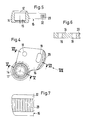
- a tie rod 1 which has an adjustably fastened ball joint 2 at one end and an immovably fastened ball joint 3 at the other end.
- the tie rod 1 is essentially U-shaped in cross section.
- the side walls 7, 8 are raised in the region of the fork head.
- the fork head 9 has a cutting edge 11 which runs obliquely to the tie rod axis 10 and which enables the ball joint 2 to pivot.
- the ball joint 2 has a ball pin 12 which is held in a joint housing 14 with the interposition of a bearing shell 13.
- the articulated housing 14 has a cup-shaped receptacle 15 for the bearing shell 13 and ball pin 12, to which a fastening plate 16 is flanged on the side and is oriented perpendicular to the central axis 17 of the movement of the ball pin 12.
- the mounting plate 16 has a bearing bore 18 which is arranged eccentrically to the central axis 17.
- the mounting plate 16 also has an elongated hole 19 which extends on a circular arc around the bearing bore 18.
- the fastening plate 16 is inserted between the side walls 7, 8 of the fork head 9 and fastened and fixed there by means of screws 22, 23.
- the screws 22, 23 are guided on the head side in inserts 24 made of plastic or metal, which are inserted into openings 25 of the fork head 9 and are held there axially by fastening flanges 26.
- inserts 27 which also have fastening flanges 28.
- the inserts serve, in particular, to evenly apply force to the tie rod 1.
- connection can be readjusted in a simple manner by loosening the screws 22, 23, pivoting the fastening plate 16 around the screw 22 and then tightening the two screws 22, 23.
- the fastening plate 16 has a toothing 29 arranged on a side surface 32 of the fastening plate 16.
- the toothing 29 is designed as an internal toothing in a circular section with a wrap angle of approximately 90 ° and engages with a screw connection 30 which is arranged perpendicular to the axis 31 of the screw 22 and has a bolt 33 and a nut 34.
- the nut 34 is supported on a contact surface 35 which is arranged inclined at a slight angle of approximately 1 ° to 1.5 ° to the perpendicular to the screw axis 36.
- a plane-parallel disk 37 is located between the contact surface 35 and the nut 34.
- the toothing 29 designed as an internal toothing is arranged on an arc around the bearing bore 18 so that it can set the mounting plate 16 in rotation about the bearing bore 18.
- the screws 22 and 23 are loosened first. Following this, the nut 34 screwed onto the bolt 33 is loosened so that the bolt 33 can be rotated and the fastening plate 16 is pivoted into the desired position via the toothing which is in engagement with the bolt 33.
- the adjustable fastening can be adjusted with normal ring or open-end spanners or with a ratchet wrench and a socket wrench insert.
- the screw connection 30 can also be arranged above or below the fastening plate 16 and can engage with a toothing arranged on or below the fastening plate 16.
- screw connections other than those shown in the exemplary embodiment can be used.
Landscapes
- Engineering & Computer Science (AREA)
- Chemical & Material Sciences (AREA)
- Combustion & Propulsion (AREA)
- Transportation (AREA)
- Mechanical Engineering (AREA)
- Steering-Linkage Mechanisms And Four-Wheel Steering (AREA)
- Pivots And Pivotal Connections (AREA)
Applications Claiming Priority (2)
| Application Number | Priority Date | Filing Date | Title |
|---|---|---|---|
| DE9004325U DE9004325U1 (de) | 1990-04-14 | 1990-04-14 | Verstellbare Befestigung eines Kugelgelenks an einer Spurstange für Lenkgestänge von Kraftfahrzeugen |
| DE9004325U | 1990-04-14 |
Publications (2)
| Publication Number | Publication Date |
|---|---|
| EP0452625A1 true EP0452625A1 (fr) | 1991-10-23 |
| EP0452625B1 EP0452625B1 (fr) | 1993-05-12 |
Family
ID=6852924
Family Applications (1)
| Application Number | Title | Priority Date | Filing Date |
|---|---|---|---|
| EP91101982A Expired - Lifetime EP0452625B1 (fr) | 1990-04-14 | 1991-02-13 | Fixation réglable d'une rotule sur une barre pour une timonerie de direction de véhicules automobiles |
Country Status (5)
| Country | Link |
|---|---|
| US (1) | US5213435A (fr) |
| EP (1) | EP0452625B1 (fr) |
| JP (1) | JPH04228373A (fr) |
| BR (1) | BR9101500A (fr) |
| DE (2) | DE9004325U1 (fr) |
Families Citing this family (5)
| Publication number | Priority date | Publication date | Assignee | Title |
|---|---|---|---|---|
| JP3711649B2 (ja) * | 1996-09-04 | 2005-11-02 | 株式会社豊田自動織機 | 車輌における車輪のトー角調整機構 |
| US7549656B2 (en) * | 2004-04-30 | 2009-06-23 | Kw Automotive, North America | Ball joint for steering knuckle |
| CN104015561B (zh) * | 2014-06-06 | 2016-08-03 | 湘电重型装备有限公司 | 一种电动轮自卸车用驱动装置 |
| US10300946B2 (en) | 2016-06-17 | 2019-05-28 | Honda Motor Co., Ltd. | Apparatus and method for adjusting a joint of a connecting rod |
| US10293915B2 (en) | 2016-12-13 | 2019-05-21 | The Boeing Company | Apparatuses and methods for aerodynamic window assemblies |
Citations (3)
| Publication number | Priority date | Publication date | Assignee | Title |
|---|---|---|---|---|
| US2077844A (en) * | 1934-09-29 | 1937-04-20 | Leighton John Wycliffe | Adjustable hinge joint |
| US4714262A (en) * | 1986-06-17 | 1987-12-22 | Trw Inc. | Variable length tie rod assembly |
| DE3739704A1 (de) * | 1987-11-24 | 1989-06-08 | Trw Ehrenreich Gmbh | Verstellbare befestigung eines kugelgelenkes an einer spurstange fuer lenkgestaenge von kraftfahrzeugen |
Family Cites Families (8)
| Publication number | Priority date | Publication date | Assignee | Title |
|---|---|---|---|---|
| US2371835A (en) * | 1942-08-31 | 1945-03-20 | Int Harvester Co | Steering mechanism |
| DE1630290A1 (de) * | 1967-05-26 | 1971-06-16 | Daimler Benz Ag | Gelenkverbindung fuer die Aufhaengung lenkbarer Raeder eines Kraftfahrzeuges |
| US3923409A (en) * | 1975-01-22 | 1975-12-02 | Gen Motors Corp | Adjustable coupling clamp assembly |
| JPS5940634B2 (ja) * | 1977-08-18 | 1984-10-01 | 大日本印刷株式会社 | 転写方法 |
| US4162859A (en) * | 1977-12-27 | 1979-07-31 | Mcafee Loyd O | Vehicle steering knuckle arm angle compensator |
| JPS5812734B2 (ja) * | 1978-09-27 | 1983-03-10 | 株式会社東芝 | 半導体装置 |
| US4875697A (en) * | 1988-12-02 | 1989-10-24 | Navistar International Transportation Corp. | Variable wheelbase length steering linkage |
| FR2651738B1 (fr) * | 1989-09-08 | 1991-12-13 | Peugeot | Biellette reglable, en particulier pour la tringlerie de direction d'une automobile. |
-
1990
- 1990-04-14 DE DE9004325U patent/DE9004325U1/de not_active Expired - Lifetime
-
1991
- 1991-02-13 EP EP91101982A patent/EP0452625B1/fr not_active Expired - Lifetime
- 1991-02-13 DE DE9191101982T patent/DE59100105D1/de not_active Expired - Fee Related
- 1991-04-11 US US07/684,045 patent/US5213435A/en not_active Expired - Fee Related
- 1991-04-11 JP JP3078933A patent/JPH04228373A/ja active Pending
- 1991-04-12 BR BR919101500A patent/BR9101500A/pt not_active IP Right Cessation
Patent Citations (3)
| Publication number | Priority date | Publication date | Assignee | Title |
|---|---|---|---|---|
| US2077844A (en) * | 1934-09-29 | 1937-04-20 | Leighton John Wycliffe | Adjustable hinge joint |
| US4714262A (en) * | 1986-06-17 | 1987-12-22 | Trw Inc. | Variable length tie rod assembly |
| DE3739704A1 (de) * | 1987-11-24 | 1989-06-08 | Trw Ehrenreich Gmbh | Verstellbare befestigung eines kugelgelenkes an einer spurstange fuer lenkgestaenge von kraftfahrzeugen |
Also Published As
| Publication number | Publication date |
|---|---|
| BR9101500A (pt) | 1991-12-03 |
| DE9004325U1 (de) | 1990-06-21 |
| EP0452625B1 (fr) | 1993-05-12 |
| DE59100105D1 (de) | 1993-06-17 |
| JPH04228373A (ja) | 1992-08-18 |
| US5213435A (en) | 1993-05-25 |
Similar Documents
| Publication | Publication Date | Title |
|---|---|---|
| EP0317734B1 (fr) | Fixation ajustable d'un joint à rotule à une barre, d'accouplement pour la timonerie de direction de véhicules | |
| EP0342412A1 (fr) | Rétroviseur à réglage motorisé | |
| DE10147588A1 (de) | Befestigungskloben zur Halterung von Gegenständen an einer Profilschiene | |
| DE102005062790A1 (de) | Scheibenwischer | |
| EP0331868A2 (fr) | Clé dynamométrique | |
| DE29800235U1 (de) | Abzieher | |
| EP0877677B1 (fr) | Dispositif servant au verrouillage d'un conteneur sur un chassis de vehicule | |
| EP1270350A2 (fr) | Dispositif d'ajustement et son outil d'actionnement | |
| EP0452625B1 (fr) | Fixation réglable d'une rotule sur une barre pour une timonerie de direction de véhicules automobiles | |
| DE3636500C2 (de) | Schutzhaube für Handwerkzeugmaschinen, insbesondere Schleifmaschinen | |
| DE3000470C2 (de) | Anhängerdeichsel | |
| DE3738434C2 (de) | Wischvorrichtung für Scheiben von Kraftfahrzeugen | |
| DE7732250U1 (de) | Spurstange fuer lenkgestaenge in kraftfahrzeugen | |
| DE69404249T2 (de) | Schraubenschlüssel, insbesondere zum auslösen oder anziehen von radmuttern oder dergleichen | |
| DE102004048879B4 (de) | Anlenkung | |
| DE202023104401U1 (de) | Lenkervorbau | |
| DE202023104397U1 (de) | Lenkervorbau | |
| EP0221255A2 (fr) | Rétroviseur pour véhicule | |
| DE3413761A1 (de) | Steckschluessel, insbesondere radmutternschluessel fuer kraftfahrzeuge | |
| DE3504315C1 (de) | Vorrichtung zum Lösen von Radmuttern und Radschrauben bei Kraftfahrzeugen | |
| DE562118C (de) | Anhaengerbremseinrichtung fuer Kraftfahrzeuge | |
| EP0431278A2 (fr) | Clef à cliquet | |
| CH687158A5 (de) | Schneepflug. | |
| DE10103175A1 (de) | Schraubenverbindung | |
| DE2200990C3 (de) | Tretkurbel für Fahrräder |
Legal Events
| Date | Code | Title | Description |
|---|---|---|---|
| PUAI | Public reference made under article 153(3) epc to a published international application that has entered the european phase |
Free format text: ORIGINAL CODE: 0009012 |
|
| 17P | Request for examination filed |
Effective date: 19910823 |
|
| AK | Designated contracting states |
Kind code of ref document: A1 Designated state(s): DE FR GB IT |
|
| 17Q | First examination report despatched |
Effective date: 19920427 |
|
| GRAA | (expected) grant |
Free format text: ORIGINAL CODE: 0009210 |
|
| AK | Designated contracting states |
Kind code of ref document: B1 Designated state(s): DE FR GB IT |
|
| REF | Corresponds to: |
Ref document number: 59100105 Country of ref document: DE Date of ref document: 19930617 |
|
| GBT | Gb: translation of ep patent filed (gb section 77(6)(a)/1977) |
Effective date: 19930621 |
|
| RAP2 | Party data changed (patent owner data changed or rights of a patent transferred) |
Owner name: TRW FAHRWERKSYSTEME GMBH & CO. KG |
|
| ET | Fr: translation filed | ||
| ITF | It: translation for a ep patent filed | ||
| PGFP | Annual fee paid to national office [announced via postgrant information from national office to epo] |
Ref country code: GB Payment date: 19980202 Year of fee payment: 8 |
|
| PGFP | Annual fee paid to national office [announced via postgrant information from national office to epo] |
Ref country code: FR Payment date: 19980216 Year of fee payment: 8 |
|
| PG25 | Lapsed in a contracting state [announced via postgrant information from national office to epo] |
Ref country code: GB Free format text: LAPSE BECAUSE OF NON-PAYMENT OF DUE FEES Effective date: 19990213 |
|
| GBPC | Gb: european patent ceased through non-payment of renewal fee |
Effective date: 19990213 |
|
| PG25 | Lapsed in a contracting state [announced via postgrant information from national office to epo] |
Ref country code: FR Free format text: LAPSE BECAUSE OF NON-PAYMENT OF DUE FEES Effective date: 19991029 |
|
| REG | Reference to a national code |
Ref country code: FR Ref legal event code: ST |
|
| PGFP | Annual fee paid to national office [announced via postgrant information from national office to epo] |
Ref country code: DE Payment date: 19991229 Year of fee payment: 10 |
|
| PG25 | Lapsed in a contracting state [announced via postgrant information from national office to epo] |
Ref country code: DE Free format text: LAPSE BECAUSE OF NON-PAYMENT OF DUE FEES Effective date: 20011201 |
|
| PG25 | Lapsed in a contracting state [announced via postgrant information from national office to epo] |
Ref country code: IT Free format text: LAPSE BECAUSE OF NON-PAYMENT OF DUE FEES;WARNING: LAPSES OF ITALIAN PATENTS WITH EFFECTIVE DATE BEFORE 2007 MAY HAVE OCCURRED AT ANY TIME BEFORE 2007. THE CORRECT EFFECTIVE DATE MAY BE DIFFERENT FROM THE ONE RECORDED. Effective date: 20050213 |
|
| PLBE | No opposition filed within time limit |
Free format text: ORIGINAL CODE: 0009261 |
|
| STAA | Information on the status of an ep patent application or granted ep patent |
Free format text: STATUS: NO OPPOSITION FILED WITHIN TIME LIMIT |