EP0452637B1 - Dispositif d'irradiation - Google Patents
Dispositif d'irradiation Download PDFInfo
- Publication number
- EP0452637B1 EP0452637B1 EP91102780A EP91102780A EP0452637B1 EP 0452637 B1 EP0452637 B1 EP 0452637B1 EP 91102780 A EP91102780 A EP 91102780A EP 91102780 A EP91102780 A EP 91102780A EP 0452637 B1 EP0452637 B1 EP 0452637B1
- Authority
- EP
- European Patent Office
- Prior art keywords
- accordance
- irradiation device
- irradiation
- container
- radiation source
- Prior art date
- Legal status (The legal status is an assumption and is not a legal conclusion. Google has not performed a legal analysis and makes no representation as to the accuracy of the status listed.)
- Expired - Lifetime
Links
Images


Classifications
-
- A—HUMAN NECESSITIES
- A61—MEDICAL OR VETERINARY SCIENCE; HYGIENE
- A61M—DEVICES FOR INTRODUCING MEDIA INTO, OR ONTO, THE BODY; DEVICES FOR TRANSDUCING BODY MEDIA OR FOR TAKING MEDIA FROM THE BODY; DEVICES FOR PRODUCING OR ENDING SLEEP OR STUPOR
- A61M1/00—Suction or pumping devices for medical purposes; Devices for carrying-off, for treatment of, or for carrying-over, body-liquids; Drainage systems
- A61M1/36—Other treatment of blood in a by-pass of the natural circulatory system, e.g. temperature adaptation, irradiation ; Extra-corporeal blood circuits
- A61M1/3681—Other treatment of blood in a by-pass of the natural circulatory system, e.g. temperature adaptation, irradiation ; Extra-corporeal blood circuits by irradiation
-
- G—PHYSICS
- G21—NUCLEAR PHYSICS; NUCLEAR ENGINEERING
- G21K—HANDLING OF PARTICLES OR IONISING RADIATION NOT OTHERWISE PROVIDED FOR; IRRADIATION DEVICES; GAMMA RAY OR X-RAY MICROSCOPES
- G21K5/00—Irradiation devices
- G21K5/02—Irradiation devices having no beam-forming means
Definitions
- the invention relates to a device for irradiating an object, in particular a liquid or gaseous medium, such as blood, stored in a container, with a radiation source for ionizing radiation, which is inserted in a shielded housing and acts on the medium to be irradiated .
- the housing receiving the radiation source is laterally provided with an open recess in its height, in which a housing part is rotatably mounted, which has a radiation chamber.
- the object to be irradiated for example a bottle
- the housing is transported. Since the object can also be rotated about its axis by means of a turntable provided in the irradiation chamber, uniform irradiation from the outside is possible, but despite the considerable construction costs, media which are filled in a bottle or in a bag and are therefore stationary can each be from one Side of the radiation source.
- the time required for this since the container and thus the medium to be irradiated has to be moved past the radiation source is considerable, and the rotational movement of the container can also have an unfavorable effect on the medium to be irradiated.
- the field of application of this radiation device is therefore limited, since it cannot be used in particular during an operation, for example in order to irradiate the blood of a patient during it.
- the object of the invention is therefore to provide an irradiation device of the aforementioned type, by means of which not only an extremely intensive and safe irradiation of a medium is to be carried out, but also a flowing medium can flow close to the radiation source, the radiation dose acting on it easily Requirements, for example depending on the flow rate, must be set accordingly. Furthermore, the equipping of the radiation device should be carried out without difficulty and thus simple handling should be provided, but it should nevertheless be reliably ensured that no rays escape uncontrolledly and that the radiation device can be operated logically and is correspondingly functional.
- the housing which is preferably designed in the form of a barrel, has a central receiving chamber on one side for the radiation source and in alignment with this on the other side has a radiation chamber for receiving a container containing the medium to be irradiated, that a rotatable or displaceably mounted slide is arranged between the receiving chamber and the radiation chamber, which has a passage opening for the into the radiation chamber insertable radiation source is provided and can be locked in different angular positions, and that the radiation chamber can be closed by an adjustable sealing plug.
- the container to be irradiated with a centrally arranged recess for receiving the radiation source, which can be formed by a helically wound tube around a hollow core receiving the radiation source or can consist of two tubes arranged at a distance from one another, whose annular space is divided by flow walls into communicating flow channels.
- a pump device for example a hose pump attached to the radiation device.
- the lever linkage that can be used for this purpose can consist in a simple manner of a rotatably mounted actuating lever arranged outside the housing, an adjusting lever attached to the slide and a connecting lever articulated thereon, and the actuating lever a releasable locking member should be assigned depending on the operating position of the sealing plug.
- the sealing plug should be insertable into an enlarged receiving opening that is machined into the housing in alignment with the receiving chamber of the housing, be provided with a cover that overlaps the receiving opening, and preferably in its edge area with a cutout for carrying out lines to be connected to the container.
- the housing should be composed of a lower part receiving the radiation source, an intermediate piece for rotatably supporting the slide and an upper part receiving the container. Furthermore, the housing can be provided with a closed casing, to which a display device can also be attached, which is mechanically connected directly to the radiation source or its lifting member. If an irradiation device is designed according to the invention, it is possible without difficulty to expose the object to be irradiated extremely intensively to the ionizing radiation emitted by the radiation source, but to irradiate it safely; but above all, a flowing medium can be irradiated without any problems.
- the housing of the irradiation device is provided with a receiving chamber into which the medium to be irradiated can be inserted in a specially designed container, and the radiation source is arranged in such a way that it can be inserted into the receiving container, with a slider to be operated only in If the introduction is to be accomplished in a predetermined operating position, the rays act from the inside on the medium enclosing the radiation source.
- the radiation intensity is thus used very well, so that the radiation time when transmitting the same radiation dose is considerably shorter than in the known device.
- the radiation device no centrifugal forces act on the medium to be irradiated, since the receptacle receiving this is arranged in a stationary manner during irradiation.
- a furthermore, the radiation can be easily dosed, for example depending on the position of the radiation source, the duration of the radiation and / or the flow rate of the medium, possibly also programmed.
- a medium can flow through the container during irradiation Radiation equipment can thus also be connected directly to a patient or used during an operation. The simple handling and the high level of operational safety ensure that the use is always safe for both the staff and a patient.
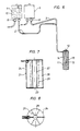
- the device shown in FIGS. 1 and 2 and designated 1 serves to irradiate an object, preferably a liquid medium 10, with ionizing rays, which can flow via a feed line 2 to a container 11 which can be used in the device 1.
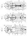
- a receptacle chamber 33 for a radiation source 41 and an irradiation chamber 35, into which the radiation source 41 can be inserted are incorporated in a barrel-shaped housing 31.
- a slide 51 which can be adjusted by means of a lever linkage 55 and by means of which the receiving chamber 33 of the radiation source 41 is shielded when the device 1 is loaded, as shown in FIG. 1.
- the container 11 for receiving the liquid 10 to be irradiated consists, as can be seen in detail in FIG. 6, of a hose 14 wound helically on a hollow core 12 and a jacket 15, so that an opening 13 is formed, into which the Radiation source 41 introduced can be.
- the container 21 shown there can also be produced from an inner tube 22 and an outer tube 24 arranged at a distance therefrom, between which intermediate walls 25 are inserted such that communicating flow channels 26 are created.
- the radiation source 41 can be introduced into the opening 23 of the inner tube 22 during an irradiation process.
- the container 11 or 21 can be directly on a patient, e.g. to irradiate its blood, which is connected, but it is also possible to connect lines 2 and 3 equipped with shut-off valves 6 to blood bags 4 and 5, in which the liquid 10 to be irradiated is temporarily stored.
- a peristaltic pump 7 attached to the irradiation device 1 the liquid 10 to be irradiated is continuously supplied to the container 11 or 21 during an irradiation process.
- the housing 31 of the radiation device 1 which is surrounded by a casing 39, consists of a lower part 32, in which the receiving chamber 33 of the radiation source 41 is provided, an upper part 34, which has the radiation chamber 35, and an intermediate piece 37 for rotatably mounting the slide 51 in a built-in one Recess 38 composed.
- the upper part 34 is furthermore equipped with a receiving opening 36 for a sealing plug 40 which is enlarged compared to the radiation chamber 35.
- the housing 31 is held by means of supports 50.
- a lifting member 43 is supported on guide rails 47 in the form of a chain drive 45 which can be driven by a motor 44 and to which a plate 46 is attached.
- the radiation source 41 is arranged on a rod 42 which projects from the lower part 32 of the housing 31 and which rests on a plate 46.
- the rod 42 also serves to shield the receiving chamber 33.
- the slide 51 can be adjusted by means of the lever linkage 55 which acts on a shaft 53 attached to the slide 51.
- the lever linkage 55 consists here of an actuating lever 56 rotatably mounted in a bracket 54 by means of a shaft 57, an adjusting lever 58 connected to the shaft 53 of the slide 51 and a connecting lever 59 which is articulated on the actuating lever 56 and the adjusting lever 58.
- the actuating lever 56 is further equipped with a locking member 60 which interacts with a stop 61 which can be adjusted by a bolt 62 against the force of a spring 63.
- a bolt 64 which is connected to the actuating lever 56 is attached and recesses 65, 66 or 67 machined into the console 54, the actuating lever 56 can be locked in the positions A, B or C.
- the sealing plug 40 is held in a height-adjustable manner by means of a bridge 73 on a support frame 71, which has two guide rails 72 for this purpose. And on the bridge 73 a windable chain 75 is attached, which is adjustable by means of a motor 74. In addition, an adjustment cam 76 is attached to the bridge 73, which interacts with the locking member 60 of the actuating lever 56.
- a stepped screw 78 By means of a stepped screw 78, the container 11 or 21 is detachably fastened to the sealing plug 40, on which a cover 77, which extends over the receiving opening 36, is attached. And in order to be able to lead the supply line 2 and the return line 3 out of the radiation chamber 35 when the container 11 or 21 is inserted in the radiation device 1, the sealing plug 40 is provided with a corresponding cutout 68 in the edge region.
- the sealing plug 40 is to be brought into the position shown in FIG. Before that, however, the slide 51 is to be rotated - as shown in FIG. 3 - in such a way that the through bore 52 incorporated into it does not align with the receiving chamber 33, so that the radiation source 41 located therein is also shielded.
- the locking member 60 attached to the operating lever 56 lies in position A of the actuating lever 56 on the stop 61, an unintentional adjustment of the slide 51 is thus excluded.
- the container 11 or 21 is screwed onto the plug 40 and this is inserted into the receiving opening 36.
- the stop 61 is adjusted against the force of the spring 63 acting on the switching cam 76 attached to the bridge 73, the actuating lever 56 can thus be adjusted in position B according to FIG.
- the container 11 or 21 is already in the radiation chamber 35, but the radiation source 41 cannot yet be introduced into it, since the through bore 52 of the slide 51 is not aligned with the receiving chamber 33.
- the radiation device 1 can, for example, be brought into an operating room or the container 11 or 21 can be connected to a patient without radiation being carried out immediately.
- the slide 51 is thereby adjusted via the lever linkage 55, as shown in FIG. 5, in such a way that the radiation source 41 is more or less inserted into the opening 13 or 23 of the container 11 or 21 can be introduced and that the located in or through this flowing medium is irradiated.
- the radiation dose that is supplied to the medium 10 can be regulated.
- a locking cylinder can be installed in the bolt 64 so that the actuating lever 56 is to be secured in positions A, B or C against inadvertent rotation.
- the radiation source 41 or the lifting member 43 assigned to it can be mechanically connected to a display device 81 attached to the casing 39 via connecting members 82. In this way, the position of the radiation source 41 can thus be determined at any time.
- control or display elements 83 or a computer with which an automatic course of treatment can be carried out and / or the radiation values are to be stored can be provided on the casing 39.
Landscapes
- Health & Medical Sciences (AREA)
- Engineering & Computer Science (AREA)
- Heart & Thoracic Surgery (AREA)
- Vascular Medicine (AREA)
- Hematology (AREA)
- General Health & Medical Sciences (AREA)
- High Energy & Nuclear Physics (AREA)
- General Engineering & Computer Science (AREA)
- Anesthesiology (AREA)
- Biomedical Technology (AREA)
- Physics & Mathematics (AREA)
- Life Sciences & Earth Sciences (AREA)
- Animal Behavior & Ethology (AREA)
- Cardiology (AREA)
- Public Health (AREA)
- Veterinary Medicine (AREA)
- Apparatus For Disinfection Or Sterilisation (AREA)
- Infusion, Injection, And Reservoir Apparatuses (AREA)
- External Artificial Organs (AREA)
- Heating, Cooling, Or Curing Plastics Or The Like In General (AREA)
- Physical Or Chemical Processes And Apparatus (AREA)
- Radiation-Therapy Devices (AREA)
Claims (18)
- Dispositif d'irradiation d'un objet, notamment d'un milieu liquide ou gazeux enfermé dans un réservoir, comme par exemple du sang, à l'aide d'une source d'irradiation à rayons ionisés qui est montée dans un boîtier blindé et qui, dans celui-ci, influe sur le milieu à soumettre à l'irradiation,
caractérisé en ce que
le boîtier (31) conçu de préférence sous forme d'un tonneau comporte d'un côté une chambre centrée (33) pour le logement de la source d'irradiation (41), et, alignée de l'autre côté de celle-ci, une chambre d'irradiation (35) destinée à recevoir un réservoir (11; 21) contenant le milieu (10) à soumettre à l'irradiation, qu'entre la chambre de logement (33) et la chambre d'irradiation (35), il est prévu un tiroir (51) p. ex. rotatif ou glissant, muni d'un passage (52) pour l'introduction de la source d'irradiation (41) dans la chambre d'irradiation (35) et positionné à divers angles, et que la chambre d'irradiation (35) se laisse obturer par un bouchon rapprochable (40). - Dispositif d'irradiation d'après la revendication 1,
caractérisé en ce que
le réservoir (11; 21) destiné à renfermer le milieu à soumettre à l'irradiation (liquide 10) est muni d'un évidement centré (13; 23) recevant la source d'irradiation (41). - Dispositif d'irradiation d'après la revendication 2,
caractérisé en ce que
le réservoir (11) est constitué par un tuyau flexible (14) enroulé sous forme hélicoïdale autour d'un noyau creux (13) recevant la source d'irradiation (41). - Dispositif d'irradiation d'après la revendication 2,
caractérisé en ce que
le réservoir (21) est constitué par deux tubes (22, 24) disposés l'un à l'intérieur de l'autre avec une certaine distance entre eux et que la chambre annulaire ainsi renfermée est subdivisée par des parois intermédiaires (25) en canaux d'écoulement (26) communiquant entre eux. - Dispositif d'irradiation d'après une ou plusieurs des revendications 2 à 4,
caractérisé en ce que
le réservoir (11; 21) se laisse brancher sur un dispositif de pompage (7), par exemple une pompe tubulaire prévue sur le dispositif d'irradiation (1). - Dispositif d'irradiation d'après une ou plusieurs des revendications 1 à 5,
caractérisé en ce que
le tiroir (51) se laisse amener par une tringlerie à leviers (55) en trois positions de service (A, B, C) où il se laisse bloquer. - Dispositif d'irradiation d'après la revendication 6,
caractérisé en ce que
la tringlerie à leviers (55) est formée par un levier d'actionnement (56) disposé à l'extérieur du boîtier (31) et logé en rotation, par un levier de réglage (58) monté sur le tiroir (51) et par un levier de raccordement (59) articulé sur ce dernier. - Dispositif d'irradiation d'après la revendication 7,
caractérisé en ce que,
au levier d'actionnement (56), il est assigné un organe de verrouillage (60) détachable en fonction de la position de service du bouchon (40). - Dispositif d'irradiation d'après une ou plusieurs des revendications 1 à 8,
caractérisé en ce que
la source d'irradiation (41) se laisse introduire dans la chambre d'irradiation (35) du boîtier (31) au moyen d'un membre de levage (43) entraîné de préférence par un moteur. - Dispositif d'irradiation d'après une ou plusieurs des revendications 1 à 9,
caractérisé en ce que,
à l'aide d'un pont (73) et d'un moteur (74), le bouchon (40) se laisse régler en hauteur sur un support (71) comprenant deux glissières de guidage (72). - Dispositif d'irradiation d'après une ou plusieurs des revendications 1 à 10,
caractérisé en ce que
le pont (73) est équipé d'une came de commande (76) qui permet de détacher l'organe de verrouillage (60) de la tringlerie à leviers (55) assignée au tiroir (51). - Dispositif d'irradiation d'après une ou plusieurs des revendications 1 à 11,
caractérisé en ce que
le réservoir (11; 21) destiné à renfermer le milieu à soumettre à l'irradiation (liquide 10) est fixé d'une manière détachable au bouchon (40), par exemple au moyen d'une vis étagée (78). - Dispositif d'irradiation d'après une ou plusieurs des revendications 1 à 12,
caractérisé en ce que
le bouchon (40) se laisse insérer dans une ouverture de logement élargie (36) pratiquée dans le boîtier (31) et alignée par rapport à la chambre de logement (33) du réservoir (11; 21). - Dispositif d'irradiation d'après la revendication 13,
caractérisé en ce que,
le bouchon (40) est muni d'un recouvrement (77) dépassant l'ouverture de logement (36). - Dispositif d'irradiation d'après une ou plusieurs des revendications 1 à 14,
caractérisé en ce que,
de préférence à un endroit extérieur, le bouchon (40) est muni d'un passage (68) destiné aux conduites (2, 3) à brancher sur le réservoir (11; 21). - Dispositif d'irradiation d'après une ou plusieurs des revendications 1 à 15,
caractérisé en ce que
le boîtier (31) consiste d'une partie inférieure (32) recevant la source d'irradiation (41), d'une pièce intermédiaire (37) pour le logement en rotation du tiroir (51) et d'une pièce supérieure (34) recevant le réservoir (11, 21). - Dispositif d'irradiation d'après une ou plusieurs des revendications 1 à 16,
caractérisé en ce que
le boîtier (31) est entouré d'un revêtement fermé (39). - Dispositif d'irradiation d'après une ou plusieurs des revendications 1 à 17,
caractérisé en ce que
sur le revêtement (39) du boîtier (31), il est prévu un indicateur (81) lié mécaniquement et directement à la source d'irradiation (41), ou à son membre de levage (43).
Applications Claiming Priority (2)
| Application Number | Priority Date | Filing Date | Title |
|---|---|---|---|
| DE4012398 | 1990-04-19 | ||
| DE4012398A DE4012398A1 (de) | 1990-04-19 | 1990-04-19 | Bestrahlungsvorrichtung |
Publications (3)
| Publication Number | Publication Date |
|---|---|
| EP0452637A2 EP0452637A2 (fr) | 1991-10-23 |
| EP0452637A3 EP0452637A3 (en) | 1992-11-25 |
| EP0452637B1 true EP0452637B1 (fr) | 1996-09-25 |
Family
ID=6404606
Family Applications (1)
| Application Number | Title | Priority Date | Filing Date |
|---|---|---|---|
| EP91102780A Expired - Lifetime EP0452637B1 (fr) | 1990-04-19 | 1991-02-26 | Dispositif d'irradiation |
Country Status (6)
| Country | Link |
|---|---|
| US (1) | US5134295A (fr) |
| EP (1) | EP0452637B1 (fr) |
| JP (1) | JPH04225200A (fr) |
| AT (1) | ATE143524T1 (fr) |
| CA (1) | CA2040546A1 (fr) |
| DE (2) | DE4012398A1 (fr) |
Families Citing this family (25)
| Publication number | Priority date | Publication date | Assignee | Title |
|---|---|---|---|---|
| DE4116022C2 (de) * | 1991-05-16 | 1995-03-23 | Isotopentechnik Dr Sauerwein G | Abschirmkörper eines Gammagraphie-Geräts |
| NL9300827A (nl) * | 1993-05-13 | 1994-12-01 | Valery Kotul | Middelen voor de behandeling van menselijk bloed. |
| US20040067157A1 (en) * | 1993-07-22 | 2004-04-08 | Clearant, Inc. | Methods for sterilizing biological materials |
| US5362442A (en) * | 1993-07-22 | 1994-11-08 | 2920913 Canada Inc. | Method for sterilizing products with gamma radiation |
| AU732122B2 (en) * | 1996-11-06 | 2001-04-12 | Stephen John Newlands | Isotope holder |
| US6342265B1 (en) * | 1997-08-20 | 2002-01-29 | Triumf | Apparatus and method for in-situ thickness and stoichiometry measurement of thin films |
| US7070607B2 (en) * | 1998-01-27 | 2006-07-04 | The Regents Of The University Of California | Bioabsorbable polymeric implants and a method of using the same to create occlusions |
| US6452200B1 (en) | 1999-05-13 | 2002-09-17 | Mds Nordion Inc. | Gap shielded container for a radioactive source |
| US20040086420A1 (en) * | 2000-03-23 | 2004-05-06 | Macphee Martin J. | Methods for sterilizing serum or plasma |
| US6682695B2 (en) * | 2001-03-23 | 2004-01-27 | Clearant, Inc. | Methods for sterilizing biological materials by multiple rates |
| US6696060B2 (en) * | 2001-06-14 | 2004-02-24 | Clearant, Inc. | Methods for sterilizing preparations of monoclonal immunoglobulins |
| US6946098B2 (en) | 2001-08-10 | 2005-09-20 | Clearant, Inc. | Methods for sterilizing biological materials |
| US20030031584A1 (en) * | 2001-08-10 | 2003-02-13 | Wilson Burgess | Methods for sterilizing biological materials using dipeptide stabilizers |
| US7252799B2 (en) * | 2001-08-31 | 2007-08-07 | Clearant, Inc. | Methods for sterilizing preparations containing albumin |
| US6749851B2 (en) | 2001-08-31 | 2004-06-15 | Clearant, Inc. | Methods for sterilizing preparations of digestive enzymes |
| US20110091353A1 (en) * | 2001-09-24 | 2011-04-21 | Wilson Burgess | Methods for Sterilizing Tissue |
| US6783968B2 (en) | 2001-09-24 | 2004-08-31 | Clearant, Inc. | Methods for sterilizing preparations of glycosidases |
| US20030095890A1 (en) * | 2001-09-24 | 2003-05-22 | Shirley Miekka | Methods for sterilizing biological materials containing non-aqueous solvents |
| US20030185702A1 (en) * | 2002-02-01 | 2003-10-02 | Wilson Burgess | Methods for sterilizing tissue |
| US20030124023A1 (en) * | 2001-12-21 | 2003-07-03 | Wilson Burgess | Method of sterilizing heart valves |
| US20040013562A1 (en) * | 2002-07-18 | 2004-01-22 | Wilson Burgess | Methods for sterilizing milk. |
| US6908591B2 (en) * | 2002-07-18 | 2005-06-21 | Clearant, Inc. | Methods for sterilizing biological materials by irradiation over a temperature gradient |
| SI1622651T1 (sl) * | 2003-01-21 | 2013-07-31 | Safe Foods Corporation | Modularna, visokovolumna, pod visokim pritiskom tekoča dezinfekcijska UV radiacija |
| DE102010054569A1 (de) * | 2010-12-15 | 2012-06-21 | Volodymyr Granovskyy | Gefäß zur Aufbewahrung von radioaktiven Materialien |
| CN104662644B (zh) | 2012-09-27 | 2018-11-27 | 斯克林集团公司 | 处理液供给装置及方法、处理液及基板处理装置及方法 |
Family Cites Families (10)
| Publication number | Priority date | Publication date | Assignee | Title |
|---|---|---|---|---|
| GB792683A (en) * | 1955-10-21 | 1958-04-02 | Nuclear Engineering Ltd | An improved apparatus for utilising the emanations from radio-active sources for medical therapy and other purposes |
| US2968734A (en) * | 1956-01-06 | 1961-01-17 | Martin Co | Device for the exposure of fluid to radiation |
| IL24713A (en) * | 1964-12-02 | 1969-06-25 | Saint Gobain Techn Nouvelles | Method and apparatus for irradiation of articles |
| FR2020234A1 (fr) * | 1968-10-09 | 1970-07-10 | Atomenergi Ab | |
| US3683183A (en) * | 1969-06-04 | 1972-08-08 | Radiation Machinery Corp | A flow-through irradiator for the extra corporeal irradiation of fluid |
| AT341049B (de) * | 1975-10-01 | 1978-01-10 | Oesterr Studien Atomenergie | Reaktor zur kontinuierlichen umsetzung von in einer rohrleitung fliessendem medium unter einwirkung ionisierender strahlung |
| FR2443122A1 (fr) * | 1978-11-14 | 1980-06-27 | Commissariat Energie Atomique | Dispositif de stockage d'une source de photons et d'irradiation d'un corps par le rayonnement de la source |
| US4464330A (en) * | 1982-05-13 | 1984-08-07 | The United States Of America As Represented By The Department Of Energy | Apparatus for irradiating a continuously flowing stream of fluid |
| SE8301762L (sv) * | 1983-03-30 | 1984-10-01 | Larsson L P Ab | Anordning vid forstoring av mikroorganismer |
| WO1987005738A1 (fr) * | 1986-03-13 | 1987-09-24 | Zahnradfabrik Friedrichshafen Ag | Systeme pour irradier des liquides au moyen de faisceaux radioactifs |
-
1990
- 1990-04-19 DE DE4012398A patent/DE4012398A1/de not_active Withdrawn
-
1991
- 1991-02-26 EP EP91102780A patent/EP0452637B1/fr not_active Expired - Lifetime
- 1991-02-26 AT AT91102780T patent/ATE143524T1/de not_active IP Right Cessation
- 1991-02-26 DE DE59108216T patent/DE59108216D1/de not_active Expired - Fee Related
- 1991-03-29 US US07/677,586 patent/US5134295A/en not_active Expired - Fee Related
- 1991-04-16 JP JP3084174A patent/JPH04225200A/ja active Pending
- 1991-04-16 CA CA002040546A patent/CA2040546A1/fr not_active Abandoned
Also Published As
| Publication number | Publication date |
|---|---|
| US5134295A (en) | 1992-07-28 |
| EP0452637A3 (en) | 1992-11-25 |
| JPH04225200A (ja) | 1992-08-14 |
| CA2040546A1 (fr) | 1991-10-20 |
| DE4012398A1 (de) | 1991-10-24 |
| DE59108216D1 (de) | 1996-10-31 |
| EP0452637A2 (fr) | 1991-10-23 |
| ATE143524T1 (de) | 1996-10-15 |
Similar Documents
| Publication | Publication Date | Title |
|---|---|---|
| EP0452637B1 (fr) | Dispositif d'irradiation | |
| EP1189661B1 (fr) | Dispositif pour la mise en oeuvre d'une therapie protonique | |
| EP0128300B1 (fr) | Branchement de canal tubulaire, en particulier pour la technique de rayonnement médical | |
| DE2942384C2 (fr) | ||
| DE1491747C2 (de) | Verfahren und Vorrichtung zum Injizieren einer Flüssigkeit in das Gefäßsystem des menschlichen Körpers | |
| CH650355A5 (de) | Radioisotopen-generator. | |
| DE10065283A1 (de) | Zentrifuge mit Blutbeutelsystem mit oberem und unterem Abgang | |
| DE3342470A1 (de) | Probenahmeeinrichtung | |
| DE69622519T2 (de) | System zum Füllen eines Narkosemittelverdunsters | |
| DE3620123A1 (de) | Mess- und bestrahlungseinrichtung fuer hohlraeume | |
| DE3221350A1 (de) | Geraet zur bereitstellung hochreinen, sterilen wassers | |
| DE2649055A1 (de) | Dentalgeraet mit instrumententraeger | |
| CH645420A5 (de) | Von aussen gehaltener zylindrischer breithalter fuer schlauchware. | |
| DE60204114T2 (de) | Nachladegerät, Kassette und Einrichtung zum Auswechseln einer Nachladekassette | |
| EP0230010B1 (fr) | Appareil de dentisterie | |
| DE60004332T2 (de) | Behälter für radioaktive stoffe | |
| DE2610290A1 (de) | Filterloser sterilisierbehaelter | |
| EP0935993A1 (fr) | Dispositif pour enrichir un liquide en gaz | |
| DE3915289A1 (de) | Vierlumige doppel-ballonsonde | |
| DE2951375A1 (de) | Einrichtung zum einbetonieren von radioaktiven abfaellen in abfallfaessern | |
| DE9403832U1 (de) | Gefäßfüllmaschine | |
| WO1997014270A1 (fr) | Four a micro-ondes, notamment pour laboratoire | |
| DE357578C (de) | Vorrichtung zum Behandeln von Fluessigkeiten mit ultravioletten Strahlen | |
| DE3514304C2 (fr) | ||
| DE69802565T2 (de) | Linearbeschleuniger |
Legal Events
| Date | Code | Title | Description |
|---|---|---|---|
| PUAI | Public reference made under article 153(3) epc to a published international application that has entered the european phase |
Free format text: ORIGINAL CODE: 0009012 |
|
| AK | Designated contracting states |
Kind code of ref document: A2 Designated state(s): AT BE CH DE ES FR GB IT LI NL SE |
|
| PUAL | Search report despatched |
Free format text: ORIGINAL CODE: 0009013 |
|
| AK | Designated contracting states |
Kind code of ref document: A3 Designated state(s): AT BE CH DE ES FR GB IT LI NL SE |
|
| 17P | Request for examination filed |
Effective date: 19930518 |
|
| 17Q | First examination report despatched |
Effective date: 19950201 |
|
| GRAA | (expected) grant |
Free format text: ORIGINAL CODE: 0009210 |
|
| AK | Designated contracting states |
Kind code of ref document: B1 Designated state(s): AT BE CH DE ES FR GB IT LI NL SE |
|
| PG25 | Lapsed in a contracting state [announced via postgrant information from national office to epo] |
Ref country code: IT Free format text: LAPSE BECAUSE OF FAILURE TO SUBMIT A TRANSLATION OF THE DESCRIPTION OR TO PAY THE FEE WITHIN THE PRE;WARNING: LAPSES OF ITALIAN PATENTS WITH EFFECTIVE DATE BEFORE 2007 MAY HAVE OCCURRED AT ANY TIME BEFORE 2007. THE CORRECT EFFECTIVE DATE MAY BE DIFFERENT FROM THE ONE RECORDED.SCRIBED TIME-LIMIT Effective date: 19960925 Ref country code: FR Effective date: 19960925 Ref country code: GB Effective date: 19960925 Ref country code: ES Free format text: THE PATENT HAS BEEN ANNULLED BY A DECISION OF A NATIONAL AUTHORITY Effective date: 19960925 Ref country code: NL Free format text: LAPSE BECAUSE OF FAILURE TO SUBMIT A TRANSLATION OF THE DESCRIPTION OR TO PAY THE FEE WITHIN THE PRESCRIBED TIME-LIMIT Effective date: 19960925 |
|
| REF | Corresponds to: |
Ref document number: 143524 Country of ref document: AT Date of ref document: 19961015 Kind code of ref document: T |
|
| REF | Corresponds to: |
Ref document number: 59108216 Country of ref document: DE Date of ref document: 19961031 |
|
| PG25 | Lapsed in a contracting state [announced via postgrant information from national office to epo] |
Ref country code: SE Effective date: 19961225 |
|
| EN | Fr: translation not filed | ||
| PG25 | Lapsed in a contracting state [announced via postgrant information from national office to epo] |
Ref country code: AT Free format text: LAPSE BECAUSE OF NON-PAYMENT OF DUE FEES Effective date: 19970226 |
|
| PG25 | Lapsed in a contracting state [announced via postgrant information from national office to epo] |
Ref country code: LI Effective date: 19970228 Ref country code: CH Effective date: 19970228 Ref country code: BE Effective date: 19970228 |
|
| NLV1 | Nl: lapsed or annulled due to failure to fulfill the requirements of art. 29p and 29m of the patents act | ||
| GBV | Gb: ep patent (uk) treated as always having been void in accordance with gb section 77(7)/1977 [no translation filed] |
Effective date: 19960925 |
|
| PLBE | No opposition filed within time limit |
Free format text: ORIGINAL CODE: 0009261 |
|
| STAA | Information on the status of an ep patent application or granted ep patent |
Free format text: STATUS: NO OPPOSITION FILED WITHIN TIME LIMIT |
|
| 26N | No opposition filed | ||
| REG | Reference to a national code |
Ref country code: CH Ref legal event code: PL |
|
| PGFP | Annual fee paid to national office [announced via postgrant information from national office to epo] |
Ref country code: DE Payment date: 20010414 Year of fee payment: 11 |
|
| PG25 | Lapsed in a contracting state [announced via postgrant information from national office to epo] |
Ref country code: DE Free format text: LAPSE BECAUSE OF NON-PAYMENT OF DUE FEES Effective date: 20020903 |