EP0452644A2 - Commande pour système de signalisation - Google Patents
Commande pour système de signalisation Download PDFInfo
- Publication number
- EP0452644A2 EP0452644A2 EP91102982A EP91102982A EP0452644A2 EP 0452644 A2 EP0452644 A2 EP 0452644A2 EP 91102982 A EP91102982 A EP 91102982A EP 91102982 A EP91102982 A EP 91102982A EP 0452644 A2 EP0452644 A2 EP 0452644A2
- Authority
- EP
- European Patent Office
- Prior art keywords
- data
- buffer
- controller
- defining
- buffers
- Prior art date
- Legal status (The legal status is an assumption and is not a legal conclusion. Google has not performed a legal analysis and makes no representation as to the accuracy of the status listed.)
- Granted
Links
Images

Classifications
-
- H—ELECTRICITY
- H04—ELECTRIC COMMUNICATION TECHNIQUE
- H04W—WIRELESS COMMUNICATION NETWORKS
- H04W88/00—Devices specially adapted for wireless communication networks, e.g. terminals, base stations or access point devices
- H04W88/18—Service support devices; Network management devices
- H04W88/185—Selective call encoders for paging networks, e.g. paging centre devices
- H04W88/187—Selective call encoders for paging networks, e.g. paging centre devices using digital or pulse address codes
Definitions
- This invention relates to a controller for control of transmission means in a signalling system.
- a controller for control of transmission means in a signalling system comprising a keyboard, a data base, first and second translation means and transmission means, wherein the data base comprises a plurality of buffers, each buffer having a first data field for defining a signalling format, a second data field for identifying a party or parties to be called, a third data field for defining a physical communications path and a fourth data field for defining an operation code and optional data; the controller being arranged such that upon initiation of a transmit command, a data buffers sets up a call and for that call the signalling format controls the first translation means for defining the translation of data input at the keyboard into data in the second and fourth data fields and the signalling format for its transmission, the communications path data controls the transmission means set-up and the format and the operations code control the second translation means for translation of the operations code and optional data into the transmitted data package.
- the invention provides a universal data base structure and translation modules controlled by formatting information stored in the data base to interpret the meaning of key strokes at the keyboard and to translate data into the correct format for transmission.
- the transmission means may be a radio base station transmitter or a modem, or other such means.
- the particular buffer which at any given moment is to control the transmission operation of the controller is, in a preferred embodiment, identified by displaying a parameter unique to the party to be called (eg. an ID or name).
- An alias buffer may be provided as a look-up table correlating ID numbers with textual names.
- a controller for control of a radio receiver in a signalling system, the controller comprising a display, a data base, a first and second translation and receiver means, wherein the data base comprises a plurality of buffers each buffer having a data field for defining a signalling format, a second data field for defining a party or parties sending or receiving a call, a third data field for defining a physical communications path and a fourth data field for defining an operation code and data field; the controller being arranged such that upon receipt of a message, a data buffer is addressed by that message and for that message, the signalling format controls the first translation means for defining the translation of data received into data to be stored in the fourth data field and to be displayed on the display.
- the received ID or operation code identifies the buffer which is to control the translation modules for translation of the incoming data.
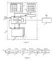
- a radio base station controller 10 comprising a central control unit 11, keyboards 12 and 13, a data base 14 comprising various buffer sets 15, 16 etc and a display 17.
- the control unit 11 is shown as having three translation modules (subroutines). These are keyboard translation module 18, transmit translation module 19 and receive translation module 20.
- the controller 10 is connected to at least one base station 20 and may have an input device 21, such as a modem connection connected to it.
- Various other audio connections are provided to and from the controller 10 and between the controller 10 and the base station 20. As the present invention is concerned with signalling (ie. data), the various audio connections are not shown.
- the data base 14 comprises seven buffer sets (of which only three are shown in Figure 1). These buffer sets represent: transmit, receive 1, receive 2, emergency, quick dial and alias buffer sets.
- the structure of a buffer of the first three buffers sets is shown in Figure 2.
- the structure of a buffer of each of the other three sets is shown in Figures 3a, 3b and 3c respectively.
- Other buffer sets may be provided - eg. transmit inhibit, transmit console ID, call ID.
- the apparatus shown operates by receiving data from the input output device 22 or the keyboards 12 and 13 via keyboard translation module 18 and passing this to the transmitter 21 via transmit translation module 19, for transmission to a mobile radio unit or other receiver, and by receipt of data signals at the base station 21, which are passed to the controller 10, via receive translation module 20, for storage in the data base 14 and/or for output from the input/output device 22 and/or display on the display 17.
- the buffer selected is the relevant buffer for the party to be called and in reception, the buffer selected is that which corresponds to the party addressed by the incoming message.
- the data field 30 identifies the format of the signalling scheme relevant for that party.
- the format information 30 controls the translation modules 18, 19 and 20 for: translation of keys of keyboard 12 into the characters which are relevant for that signalling scheme; translation of data to be transmitted from a standard format in memory to the format specific to that signalling scheme; and translation of the received data into a standard format for display or storage.
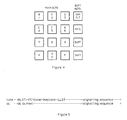
- the keyboard 12 is shown in Figure 4. It is a feature of the controller according to the preferred embodiment of the invention that the same keyboard can be used for any signalling scheme.
- the main key definitions are as follows:- 0 - 9 are number entry keys * as part of an ID code entry is used as a wild card, except for DTMF where it is a valid number * by itself is the generic enable transmit function # is the generic clear display/pending operation function, except for DTMF where it is a valid number.
- Keyboard 13 (Figure 1) has sixteen customisable keys which may be programmed to perform the same functions as some of the above key combinations.
- Translation module 18 interprets the meaning of the various keys, in accordance with the format information in section 30 of the buffer. For example, if the format information 30 identifies that the current format is DTMF, the pressing of key * will be interpreted as that DTMF tone, whereas in other formats, it will have other meanings.
- a data packet Before data can be transmitted from the base station 21, a data packet must be built by the central control unit 11, the physical parameters of the base station 20 must be set (eg. signalling modulation, baud rate, channel etc) and other aspects of the system have to be controlled to suit the particular signalling scheme selected. Likewise, when a signal is received, it must be decoded before the content of the message can be stored or displayed. The purpose of the data base 14 is to facilitate carrying out of these functions.
- the buffer set 15 comprises the transmit buffers, each having the structure shown in Figure 2.
- the buffer comprises various data fields: format information, ID code, base station control information, an operation code, data and the transmit time. The number of bits allocated in the buffer to store these various items of information are shown in the figure.
- the format information 30 identifies the signalling scheme to be used. Such schemes include MDC-600, MDC-1200, DTMF, Digital Dial, Select 5, Quick Call 1 or 2 etc. Virtually any other existing signalling scheme can be catered for, and new signalling schemes not yet devised can be included. One of the 16 available format codes is reserved for the alias function, which is described below.
- the ID code 31 identifies the party to be called.
- An ID code is a number of up to 12 digits, where each digit uses the hex range $0 to $F.
- the translation of the ID code to the specific transmit or display format required by the signalling scheme is done by the transmit translation module 19 or the display translation module 20.
- the base station control information 32 controls which base station is to be used from various base stations that may be connected to the controller 10 and controls various aspects of that base station, including modulation type, channel, baud rate etc. It can also include control of operation of repeater access.
- the operation code 33 is internal to the controller 10 and controls the central controller unit 11.
- the data 34 is the actual data to be transmitted in the data packet.
- the time 35 is the time of transmission.
- the transmit buffer set holds the last fifteen transmitted messages on encode only systems, or when an enhanced 4 X 40 character display 17 is fitted, otherwise it holds the last transmitted message.
- the buffer is LIFO.
- each ID code is associated base station transmit parameters. These include: Base station 1 to 4 or Phone patch 1, 2 Transmit frequency 1 to 8 Transmit PL code 1 to 8 Base state (Coded/Clear, Main/Standby, Alternate Line) RA if used before tx Note: transmit with or without PL is implicit in the F or PL parameter, and does not have to be defined here. Similarly, the pretime parameter is defined per base station.
- the ID code may be a pointer to an entry in the quick dial or alias buffers, and these two buffers can also include the base station parameters. If the ID code points to an alias entry then the alias name will be displayed and not the ID number.
- the base station parameters can be pointers to entries in the alias buffer.
- Each ID code is accompanied by four bytes; op. code, time stamp (2) and data.
- the op. code byte records the type of transmission, and the time stamp byte the time of the transmission (in minutes only since we can reconstruct the rest from the current time).
- the data byte holds any op. code specific data transmitted.
- the first stage in any transmit sequence is to select the ID code to be used.
- the ID code identifies the party to be called.
- the controller 10 normally uses the currently displayed ID for any transmit sequence, so the required ID can be taken from one of the buffers (as will be explained below), or entered manually from the keyboard 12 ( Figure 4).
- Certain signalling schemes such as DTMF Digital Dial
- the controller 10 recognizes this state if the user clears the display (with # key) and then selects the transmit operation. In this case, only manual keyboard entry is allowed.
- a normal (unit) ID code is entered using keys 0 - 9 for the numbers and SHFT together with keys 0 - 5 for the hexadecimal numbers $A to $F.
- the values allowed for an ID are signalling scheme dependent. Some signalling schemes allow one or more of the ID digits to be wild cards and the * key is used for this. DTMF signalling can use * and # as valid ID digits. Some signalling schemes use special ID codes for group/fleet operations and these are supported by SPCL together with 5(F) or 6(G) keys. Some schemes derive the group/fleet mode from certain digit sequences and for these the ID is entered as if it was a unit code.
- the programmer can also define a range of ID values that is a sub-set of the normal range, and it can restrict the use of the wild card entry to specific digit positions only or to one digit at a time.
- the transmit function After selecting the ID of the party to be called, the transmit function must be selected. For this, one of the pre-defined function keys is pressed. Some functions require an additional data entry. The display will prompt for this. Some functions can only be selected via the menus. The table below shows the different possibilities.
- the base station transmit control, tone or dc signal is sent first to put the base station into transmit mode, followed by the signalling sequence.
- a PTT initiated signalling sequence can be followed by other user initiated sequences and/or by voice.
- the sequences can be cascaded. For example, RAT (repeater access tone) followed by PTT ID. Note, however, that RAT must always be first. For the manual RAT, Select Call needs a user key entry. Other examples follow in the tables below.
- This transmit function is a response to a received signalling sequence. Examples are shown in Table 7.
- This transmit function is a user initiated transmit sequence with user-entered data. Examples are shown in table 8.
- the controller state is normal ie with PL squelch before data entry. After data entry, the base or controller may be put into monitor mode before transmit or the transmission made directly.
- This transmit function is a user-initiated transmit sequence with no user-entered data.
- An example is radio check.
- the entry, display and controller state are as follows:
- This transmit function is a user-initiated transmit sequence without any ID entry.
- An example is DTMF or Digital Dial manual transmit.
- the entry, display and controller state are as follows:
- the function After selecting the transmit function, the function must be enabled.
- the transmit sequence is started by pressing the * key.
- selecting the function also enables the transmit sequence.
- the display first shows “wait” flashing until the busy condition is over.
- the controller sends a tone or a DC control signal to the base station 20 and optional RAT. After a pre-time delay, it sends the data for transmission.
- the display is steady to indicate the data transmit mode and a side-tone (optional) is heard on the controllers speaker (not shown in the figures).
- the display flashes whilst waiting for a response.
- a PTT initiated transmit sequence is started by the user pressing the PTT button or by an external (paging) PTT input. Response transmit sequences are initiated automatically.
- PTT initiated and response data sequences are not repeated. Transmit data sequences may be sent once only, repeated until a data response is received, repeated until a specific data response is received, or repeated a given number of times.
- an associated operation code 33 is stored in the respective buffer in data field 15.
- the control unit 11 reads the format 30 and the op code 33 from the buffer and uses this information to construct a transmission package in a translation sub-routine in control unit 11.
- the programmer For each type of transmit sequence, the programmer defines whether it is to be sent to the printer output port. This definition also includes whether each repetition or retry is printed etc.
- Each receive buffer of the receive buffer set has the same layout as a transmit buffer of the transmit buffer set 15, as shown in Figure 2, however the format 30 identifies the type of signalling scheme received, the ID 31 identifies the party sending the message, the base station 32 identifies the settings of the base station during reception of the message, the data 34 is the received message and the time 35 is the time of receipt.
- the receive 1 buffer set hold the last fifteen received and displayed ID codes.
- the buffer can be LIFO or FIFO.
- the ID codes are placed in this buffer by the receive translation module 20, which also translates them from the specific receive format to the general format mentioned above.
- Accompanying each ID code are associated base station receive parameters.
- the ID code and the base station parameters may be pointers to entries in the alias buffer.
- the ID code is also accompanied by an op. code, a time stamp and a data byte.
- the op. code byte records the received operation, and the time stamp byte the time of transmission from the mobile (again in minutes).
- the data byte holds any op. code specific data.
- the receive 2 buffer set is similar to the receive 1 buffer set, but serves for received ID codes that were not displayed.
- the receive functions are largely the reverse of the transmit functions.
- the aim is to enable any received message to be stored in a uniform manner in memory.
- the control unit 11 selects one of the receive buffers of the receive buffer set 16.
- the end result of the receive operation is the insertion of the received data in the data field 34 or a temporary buffer (not shown in the figures).
- the programmer defines which receive functions are enabled, and into which buffer they are stored.
- the buffer type in turn defines whether the receive function is displayed or not, as will be explained below.
- the programmer also defines whether a response will be sent, and whether the received function affects the audio console muting.
- the printer port output for each receive function is also enabled by the programmer.
- the controller can be programmed to (i) accept all messages; (ii) accept a message if the receive ID is within an ID/Group/Fleet range; or (iii) accept a message if the status key matches.
- the programmer defines which received functions are accepted by the controller 10. For each signalling scheme the programmer gives a list of the possible receive functions.
- the programmer defines a range of unit ID codes and fleet/group ID codes. For each received function which will be accepted, the programmer defines if it will also be tested against the unit ID range (also known as the monitor range). Testing of group/fleet codes against the programmer defined range is set by the programmer, but the general group/fleet rang check can be set or cleared by the use of the soft key "GRP/FLT".
- status bounds can be exclusive (one value only), or inclusive (lower and upper limits).
- the range allowed is normally from 0 to 255.
- the programmer or menu defines whether the received function is stored in receive buffer 1 (and is therefore displayed) or in receive buffer 2 (which is not displayed).
- the programmer can define whether the controller will send an acknowledge signal (ACK) to each receive function which normally receives one.
- ACK acknowledge signal
- the programmer defines which received functions are also sent to the printer port.
- the controller In normal received mode, the controller also mutes the received audio until a pre-defined level of audio activity is detected. The audio mute is then extended to the period of time it takes for the signalling detection software to determine if the audio is voice or signalling. If it is voice, then the audio is unmuted. On the other hand, if the signalling is detected, the audio remains muted for the duration of the signalling sequence. At the end of this period, the audio is unmuted, depending on the specific signalling function received.
- Received signalling sequences which are detected in the middle of a voice reception will mute the audio for the duration of the sequence only.
- Each buffer of the emergency buffer set comprises all the information of a transmit or receive buffer except the operation code.
- Each buffer of the quick dial has only the format, ID code and base station control information.
- This buffer is a pre-programmed list of ten ID codes or alias names with all associated base station parameters. Op. code, time stamp or data bytes are not needed.
- the alias buffer set is essentially a look-up table correlating the ID code 31 with a name 40 and a format for calling that party. In other words, instead of having the ID code appear on the screen 17, the actual name of the party appears and the format which should be used for calling that party is already stored.
- the alias buffer set is a pre-programmed list of up to 400 alias names, and each name can be up to eight alpha-numeric characters.
- the alias names are linked either to an ID code, or a data field value in the general form, or to a base station parameter.
- the transmit alias list buffer is also used to check for a match between a received unit ID and the ID alias list, or data value and the non-ID alias list. If a match is found then the alias name is substituted on the display and print outputs.
- bits in a qualifier field of the ID field can also qualify the console response to a given ID/data value. The bit actions are detailed below. A user par determines whether unqualified ID's/data field values are accepted or rejected. The qualified response then becomes the reverse of the general response.
- Registration is the process of registering or logging the presence or absence of users during any 24 hour period.
- the period is defined by a start time in hours from 00 to 23.
- a repeat count is define by a number 1 to 24.
- 1 means registration is active only once a day at the start time
- 2 means twice a day - start time and start time + 12 hours, and so on. Since repeats must be in a whole number of hours, repeat counts 5, 7, 9, 10, 11, 13 to 23 are not allowed.
- Registration can be active or passive. Active registration consists of polling each listed user with a predefined code which givens a response. If no response was obtained then the poll will be repeated again at the time set by the repeat count. (see also registration qualifier, quiet/noisy registration). Passive registration consists of checking each incoming code to see if it is one of the listed user. The repeat count here determines at what time the console checks the state of the registration list. (Consider also registration qualifier, quiet/noisy registration).
- the user ID in the alias list can have a qualifier bit set.
- the qualifier bit tells the console to use a status poll and only register on a given status. The status required must be entered into the alias list, with the registration flag set.
- the qualifier bit tells the console to check also in the alias list for a status, message, or vehicle status with the registration flag set. Thus a listed user sending a non listed status/message/vehicle status will not be registered.
- the qualifier bit is set as before but no registration flags are set on statuses etc. The reception of the registration code will cause the user to be registered, whereas the qualifier bit will prevent other codes from the same user from registering him.
- Quiet/Noisy Registration determines the action to be taken at the repeat time for listed but not yet registered users. On active registration these users will be polled again if noisy is set, or just listed onto the console display if quiet is set. On passive registration, for quiet set they are just listed. If noisy is set then a predetermined poll code will be sent.
- the packet of data to be transmitted essentially comprises the data in section 34 of the buffer.
- the package transmitted results from a combination of the data and the op code in sections 34 and 33 respectively.
- the data 34 may have a number of functions. For example it may define the specific receiver function, eg. illuminate an LED or display a "canned" message. As another example it may poll the operator status - ie. start sending a query command "what is your status", polling each receiver until a particular status is reached. Many other examples can be considered.
- the data 34 may be supplemented by other data from the keyboard 12 (stored in memory) or the input/output device 21.
- the buffer upon initiation of the transmit command (enable transmit function), the buffer sets up the call and the format information defines the manner in which the operation code and data are to be translated into a transmission packet, as well as the signalling format for its transmission.
- the base station information 32 controls the base station 30 to define the communications path through which the data is to be transmitted (including choice of transmitter, frequency, modulation and baud rate).
- the translation means determines its meaning in terms of the information to be displayed.
Landscapes
- Engineering & Computer Science (AREA)
- Computer Networks & Wireless Communication (AREA)
- Signal Processing (AREA)
- Mobile Radio Communication Systems (AREA)
Applications Claiming Priority (2)
| Application Number | Priority Date | Filing Date | Title |
|---|---|---|---|
| GB909008537A GB9008537D0 (en) | 1990-04-17 | 1990-04-17 | Controller for a signalling system |
| GB9008537 | 1990-04-17 |
Publications (3)
| Publication Number | Publication Date |
|---|---|
| EP0452644A2 true EP0452644A2 (fr) | 1991-10-23 |
| EP0452644A3 EP0452644A3 (en) | 1993-04-28 |
| EP0452644B1 EP0452644B1 (fr) | 1997-07-09 |
Family
ID=10674480
Family Applications (1)
| Application Number | Title | Priority Date | Filing Date |
|---|---|---|---|
| EP19910102982 Expired - Lifetime EP0452644B1 (fr) | 1990-04-17 | 1991-02-28 | Commande pour système de signalisation |
Country Status (3)
| Country | Link |
|---|---|
| EP (1) | EP0452644B1 (fr) |
| DE (1) | DE69126732T2 (fr) |
| GB (1) | GB9008537D0 (fr) |
Cited By (1)
| Publication number | Priority date | Publication date | Assignee | Title |
|---|---|---|---|---|
| WO2007006110A3 (fr) * | 2005-07-11 | 2008-01-10 | Control Service Do Brasil Ltda | Systeme de surveillance et de controle d'equipement de radiocommunications |
Family Cites Families (3)
| Publication number | Priority date | Publication date | Assignee | Title |
|---|---|---|---|---|
| US4787028A (en) * | 1985-09-03 | 1988-11-22 | Ncr Corporation | Multicommunication protocol controller |
| EP0247144A1 (fr) * | 1985-11-27 | 1987-12-02 | Hughes Aircraft Company | Unite d'interface de donnees numeriques |
| US5142693A (en) * | 1988-08-22 | 1992-08-25 | Motorola, Inc. | Data capable radio communication console |
-
1990
- 1990-04-17 GB GB909008537A patent/GB9008537D0/en active Pending
-
1991
- 1991-02-28 EP EP19910102982 patent/EP0452644B1/fr not_active Expired - Lifetime
- 1991-02-28 DE DE1991626732 patent/DE69126732T2/de not_active Expired - Fee Related
Cited By (1)
| Publication number | Priority date | Publication date | Assignee | Title |
|---|---|---|---|---|
| WO2007006110A3 (fr) * | 2005-07-11 | 2008-01-10 | Control Service Do Brasil Ltda | Systeme de surveillance et de controle d'equipement de radiocommunications |
Also Published As
| Publication number | Publication date |
|---|---|
| EP0452644B1 (fr) | 1997-07-09 |
| HK1001113A1 (en) | 1998-05-22 |
| DE69126732D1 (de) | 1997-08-14 |
| GB9008537D0 (en) | 1990-06-13 |
| DE69126732T2 (de) | 1998-01-15 |
| EP0452644A3 (en) | 1993-04-28 |
Similar Documents
| Publication | Publication Date | Title |
|---|---|---|
| US5327479A (en) | Telecommunication device for the deaf with interrupt and pseudo-duplex capability | |
| EP0693860A2 (fr) | Appareil portable de radio-communications | |
| US6278886B1 (en) | Device and method for inputting and transmitting messages in a predetermined sequence in a portable telephone | |
| GB2338577A (en) | Transmitting data to e.g. a pager | |
| US6408176B1 (en) | Method and apparatus for initiating a communication in a communication system | |
| KR0122445B1 (ko) | 팩시밀리의 다중식별정보 등록 및 선택송신방법 | |
| US5287549A (en) | Commuication device and method using transceiver squelch control | |
| EP0478126A2 (fr) | Système de communication par bus série utilisé entre microprocesseur et dispositif externe | |
| EP0452644A2 (fr) | Commande pour système de signalisation | |
| WO1985002963A1 (fr) | Systeme de communication ayant des terminaux de donnees reconfigurables | |
| EP0793878A1 (fr) | Dispositif de reception et d'emission radio et procede de reception et d'emission de signaux radio | |
| HK1001113B (en) | Controller for a signalling system | |
| JPH09266510A (ja) | ページャへのメッセージ作成方式 | |
| KR100619905B1 (ko) | 피티티 서비스 이동 통신 시스템 및 그 방법 | |
| KR100241898B1 (ko) | 전화기의 비밀번호 노출 방지 장치 및 방법 | |
| KR100262952B1 (ko) | 양방향 무선호출 메시지 송수신 장치 및 수신방법 | |
| KR19990016061A (ko) | 적외선 통신을 이용한 무선호출정보 표시 방법 및 문자정보입력 방법 | |
| KR19980702769A (ko) | 다중 억세스 통신 시스템에서의 사용을 위한 가입자 유니트 | |
| KR960013378B1 (ko) | 문자 페이저 메시지 송신 방법 | |
| KR960016902B1 (ko) | 페이징 시스템(paging system)에 있어서의 텍스트(text) 송수신장치 및 그에 따른 통신방법 | |
| KR20030096654A (ko) | 대용량 sms 전송 방법 | |
| JPH01212061A (ja) | ポケットベル用文字情報送信装置 | |
| JP2969191B2 (ja) | メッセージ情報伝送システム及び受信装置 | |
| KR19990016768A (ko) | 전화기에서 디티엠에프를 이용한 문자정보 서비스방법 | |
| KR970072752A (ko) | 자유문장 송수신 무선호출기 및 그 제어방법 |
Legal Events
| Date | Code | Title | Description |
|---|---|---|---|
| PUAI | Public reference made under article 153(3) epc to a published international application that has entered the european phase |
Free format text: ORIGINAL CODE: 0009012 |
|
| AK | Designated contracting states |
Kind code of ref document: A2 Designated state(s): DE FR GB IT |
|
| PUAL | Search report despatched |
Free format text: ORIGINAL CODE: 0009013 |
|
| AK | Designated contracting states |
Kind code of ref document: A3 Designated state(s): DE FR GB IT |
|
| 17P | Request for examination filed |
Effective date: 19931008 |
|
| 17Q | First examination report despatched |
Effective date: 19950901 |
|
| GRAG | Despatch of communication of intention to grant |
Free format text: ORIGINAL CODE: EPIDOS AGRA |
|
| GRAH | Despatch of communication of intention to grant a patent |
Free format text: ORIGINAL CODE: EPIDOS IGRA |
|
| GRAH | Despatch of communication of intention to grant a patent |
Free format text: ORIGINAL CODE: EPIDOS IGRA |
|
| GRAA | (expected) grant |
Free format text: ORIGINAL CODE: 0009210 |
|
| AK | Designated contracting states |
Kind code of ref document: B1 Designated state(s): DE FR GB IT |
|
| ET | Fr: translation filed | ||
| REF | Corresponds to: |
Ref document number: 69126732 Country of ref document: DE Date of ref document: 19970814 |
|
| ITF | It: translation for a ep patent filed | ||
| PLBE | No opposition filed within time limit |
Free format text: ORIGINAL CODE: 0009261 |
|
| STAA | Information on the status of an ep patent application or granted ep patent |
Free format text: STATUS: NO OPPOSITION FILED WITHIN TIME LIMIT |
|
| 26N | No opposition filed | ||
| REG | Reference to a national code |
Ref country code: GB Ref legal event code: IF02 |
|
| PGFP | Annual fee paid to national office [announced via postgrant information from national office to epo] |
Ref country code: GB Payment date: 20050110 Year of fee payment: 15 |
|
| PGFP | Annual fee paid to national office [announced via postgrant information from national office to epo] |
Ref country code: FR Payment date: 20050202 Year of fee payment: 15 |
|
| PG25 | Lapsed in a contracting state [announced via postgrant information from national office to epo] |
Ref country code: IT Free format text: LAPSE BECAUSE OF NON-PAYMENT OF DUE FEES;WARNING: LAPSES OF ITALIAN PATENTS WITH EFFECTIVE DATE BEFORE 2007 MAY HAVE OCCURRED AT ANY TIME BEFORE 2007. THE CORRECT EFFECTIVE DATE MAY BE DIFFERENT FROM THE ONE RECORDED. Effective date: 20050228 |
|
| PGFP | Annual fee paid to national office [announced via postgrant information from national office to epo] |
Ref country code: DE Payment date: 20050228 Year of fee payment: 15 |
|
| PG25 | Lapsed in a contracting state [announced via postgrant information from national office to epo] |
Ref country code: GB Free format text: LAPSE BECAUSE OF NON-PAYMENT OF DUE FEES Effective date: 20060228 |
|
| PG25 | Lapsed in a contracting state [announced via postgrant information from national office to epo] |
Ref country code: DE Free format text: LAPSE BECAUSE OF NON-PAYMENT OF DUE FEES Effective date: 20060901 |
|
| GBPC | Gb: european patent ceased through non-payment of renewal fee |
Effective date: 20060228 |
|
| REG | Reference to a national code |
Ref country code: FR Ref legal event code: ST Effective date: 20061031 |
|
| PG25 | Lapsed in a contracting state [announced via postgrant information from national office to epo] |
Ref country code: FR Free format text: LAPSE BECAUSE OF NON-PAYMENT OF DUE FEES Effective date: 20060228 |