EP0452647A1 - Dispositif de fixation et de refroidissement de pièces disposées côte à côte et support pour plusieurs dispositifs - Google Patents
Dispositif de fixation et de refroidissement de pièces disposées côte à côte et support pour plusieurs dispositifs Download PDFInfo
- Publication number
- EP0452647A1 EP0452647A1 EP91103091A EP91103091A EP0452647A1 EP 0452647 A1 EP0452647 A1 EP 0452647A1 EP 91103091 A EP91103091 A EP 91103091A EP 91103091 A EP91103091 A EP 91103091A EP 0452647 A1 EP0452647 A1 EP 0452647A1
- Authority
- EP
- European Patent Office
- Prior art keywords
- cooling
- workpiece
- heat sink
- workpiece holding
- workpieces
- Prior art date
- Legal status (The legal status is an assumption and is not a legal conclusion. Google has not performed a legal analysis and makes no representation as to the accuracy of the status listed.)
- Granted
Links
- 238000001816 cooling Methods 0.000 title claims abstract description 28
- 238000000576 coating method Methods 0.000 claims abstract description 21
- 239000011248 coating agent Substances 0.000 claims abstract description 10
- 239000004809 Teflon Substances 0.000 claims abstract description 5
- 229920006362 Teflon® Polymers 0.000 claims abstract description 5
- 238000000034 method Methods 0.000 claims description 10
- 229910000831 Steel Inorganic materials 0.000 claims description 4
- 239000012791 sliding layer Substances 0.000 claims description 4
- 239000010959 steel Substances 0.000 claims description 4
- 239000012809 cooling fluid Substances 0.000 claims description 3
- 230000001105 regulatory effect Effects 0.000 claims description 3
- 238000001771 vacuum deposition Methods 0.000 claims description 3
- 238000003825 pressing Methods 0.000 claims description 2
- 239000011362 coarse particle Substances 0.000 abstract description 3
- 239000010419 fine particle Substances 0.000 abstract description 3
- 238000004519 manufacturing process Methods 0.000 abstract description 3
- 210000002445 nipple Anatomy 0.000 description 12
- 239000002826 coolant Substances 0.000 description 5
- 229910052751 metal Inorganic materials 0.000 description 5
- 239000002184 metal Substances 0.000 description 5
- 239000011888 foil Substances 0.000 description 4
- 239000000498 cooling water Substances 0.000 description 3
- 210000003739 neck Anatomy 0.000 description 3
- XKRFYHLGVUSROY-UHFFFAOYSA-N Argon Chemical compound [Ar] XKRFYHLGVUSROY-UHFFFAOYSA-N 0.000 description 2
- 239000000969 carrier Substances 0.000 description 2
- 239000000110 cooling liquid Substances 0.000 description 2
- 239000010410 layer Substances 0.000 description 2
- 239000000463 material Substances 0.000 description 2
- XLYOFNOQVPJJNP-UHFFFAOYSA-N water Substances O XLYOFNOQVPJJNP-UHFFFAOYSA-N 0.000 description 2
- 229910000906 Bronze Inorganic materials 0.000 description 1
- 241000446313 Lamella Species 0.000 description 1
- 229910001128 Sn alloy Inorganic materials 0.000 description 1
- 229910000639 Spring steel Inorganic materials 0.000 description 1
- 229910001315 Tool steel Inorganic materials 0.000 description 1
- YVIMHTIMVIIXBQ-UHFFFAOYSA-N [SnH3][Al] Chemical compound [SnH3][Al] YVIMHTIMVIIXBQ-UHFFFAOYSA-N 0.000 description 1
- 229910052782 aluminium Inorganic materials 0.000 description 1
- XAGFODPZIPBFFR-UHFFFAOYSA-N aluminium Chemical compound [Al] XAGFODPZIPBFFR-UHFFFAOYSA-N 0.000 description 1
- 229910052786 argon Inorganic materials 0.000 description 1
- QVGXLLKOCUKJST-UHFFFAOYSA-N atomic oxygen Chemical compound [O] QVGXLLKOCUKJST-UHFFFAOYSA-N 0.000 description 1
- 230000005540 biological transmission Effects 0.000 description 1
- 239000010974 bronze Substances 0.000 description 1
- 230000003749 cleanliness Effects 0.000 description 1
- 239000002131 composite material Substances 0.000 description 1
- KUNSUQLRTQLHQQ-UHFFFAOYSA-N copper tin Chemical compound [Cu].[Sn] KUNSUQLRTQLHQQ-UHFFFAOYSA-N 0.000 description 1
- 238000005260 corrosion Methods 0.000 description 1
- 230000007797 corrosion Effects 0.000 description 1
- 238000005520 cutting process Methods 0.000 description 1
- 230000017525 heat dissipation Effects 0.000 description 1
- 239000012212 insulator Substances 0.000 description 1
- 239000001301 oxygen Substances 0.000 description 1
- 229910052760 oxygen Inorganic materials 0.000 description 1
- 238000005245 sintering Methods 0.000 description 1
- 238000004544 sputter deposition Methods 0.000 description 1
- 239000010935 stainless steel Substances 0.000 description 1
- 229910001220 stainless steel Inorganic materials 0.000 description 1
- 239000013585 weight reducing agent Substances 0.000 description 1
Images

Classifications
-
- C—CHEMISTRY; METALLURGY
- C23—COATING METALLIC MATERIAL; COATING MATERIAL WITH METALLIC MATERIAL; CHEMICAL SURFACE TREATMENT; DIFFUSION TREATMENT OF METALLIC MATERIAL; COATING BY VACUUM EVAPORATION, BY SPUTTERING, BY ION IMPLANTATION OR BY CHEMICAL VAPOUR DEPOSITION, IN GENERAL; INHIBITING CORROSION OF METALLIC MATERIAL OR INCRUSTATION IN GENERAL
- C23C—COATING METALLIC MATERIAL; COATING MATERIAL WITH METALLIC MATERIAL; SURFACE TREATMENT OF METALLIC MATERIAL BY DIFFUSION INTO THE SURFACE, BY CHEMICAL CONVERSION OR SUBSTITUTION; COATING BY VACUUM EVAPORATION, BY SPUTTERING, BY ION IMPLANTATION OR BY CHEMICAL VAPOUR DEPOSITION, IN GENERAL
- C23C14/00—Coating by vacuum evaporation, by sputtering or by ion implantation of the coating forming material
- C23C14/22—Coating by vacuum evaporation, by sputtering or by ion implantation of the coating forming material characterised by the process of coating
- C23C14/54—Controlling or regulating the coating process
- C23C14/541—Heating or cooling of the substrates
-
- C—CHEMISTRY; METALLURGY
- C23—COATING METALLIC MATERIAL; COATING MATERIAL WITH METALLIC MATERIAL; CHEMICAL SURFACE TREATMENT; DIFFUSION TREATMENT OF METALLIC MATERIAL; COATING BY VACUUM EVAPORATION, BY SPUTTERING, BY ION IMPLANTATION OR BY CHEMICAL VAPOUR DEPOSITION, IN GENERAL; INHIBITING CORROSION OF METALLIC MATERIAL OR INCRUSTATION IN GENERAL
- C23C—COATING METALLIC MATERIAL; COATING MATERIAL WITH METALLIC MATERIAL; SURFACE TREATMENT OF METALLIC MATERIAL BY DIFFUSION INTO THE SURFACE, BY CHEMICAL CONVERSION OR SUBSTITUTION; COATING BY VACUUM EVAPORATION, BY SPUTTERING, BY ION IMPLANTATION OR BY CHEMICAL VAPOUR DEPOSITION, IN GENERAL
- C23C14/00—Coating by vacuum evaporation, by sputtering or by ion implantation of the coating forming material
- C23C14/22—Coating by vacuum evaporation, by sputtering or by ion implantation of the coating forming material characterised by the process of coating
- C23C14/50—Substrate holders
Definitions
- the invention relates to a device for holding and cooling workpieces arranged next to one another according to the preamble of patent claim 1 and a method for coating workpieces inserted into the device with a sliding layer of certain hardness according to the preamble of patent claim 9.
- a device not belonging to the state of the art for a method described in EP-PA 0 272 447 for the production of a composite material as a sliding layer on bearing shells has a channel-shaped surface into which the bearing shell blanks to be coated are inserted and each with one to be screwed to the long sides of the surface Sidebar be pressed against the surface of the channel-shaped surface.
- the baseline of the trough-shaped surface is cooled by a longitudinal bore on the bottom of the wall of the device, if possible along a line.
- the workpieces could either be inserted inside the vacuum chamber or outside with the device unscrewed from the vacuum chamber. If the device was unscrewed from the vacuum chamber, this was time-consuming and tedious on the one hand; care also had to be taken to ensure that no cooling liquid ran into the vacuum chamber. It was possible to insert the workpieces in the vacuum chamber in order to avoid leakage of the cooling liquid, but this increased the throughput time per coated workpiece due to the downtime of the vacuum coating chamber.
- Another device described in DE-OS 37 17 712 allows the workpieces to be inserted into a workpiece holder outside the vacuum coating chamber.
- a cavity filled with a coolant and extending almost over the entire bearing surface of the bearing shells was present as a heat store.
- Special precautions were taken to dissipate the heat absorbed by the heat accumulator during the coating process on a head part of the workpiece holder.
- a metal shell with a good heat transfer was used as the bearing surface for the bearing shell blanks was achieved by lamellas, wires or strips.
- DE-OS 37 17 712 allows the workpieces to be inserted outside the vacuum chamber, but was heavy and therefore unwieldy.
- the invention has for its object to provide a device for receiving workpieces, in particular bearing shell blanks, which reduces the downtimes of the vacuum chamber while ensuring good coating quality.
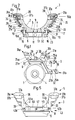
- Nine supports 1 are arranged in the vacuum chamber.
- Each heat sink and workpiece holder pair 3 consists of an elongated workpiece holder and a heat sink part 5 and 6 .
- Workpiece holding and heat sink parts 5 and 6 are put on one another without tools and can also be detached from one another again without tools, the heat sink part 5 always remaining firmly connected to the carrier 1 .
- In the assembled state of the workpiece holding portion 5 lies with its disposed in its bottom region 8 of the heat transfer surface 7 on one of the heat transfer surface 7 adapted cooling surface 9 of the heat sink part. 6
- the cooling surface 9 is an approximately 0.3 mm thick steel foil 11 , which covers a cavity 13 through which water as cooling fluid flows.
- Stainless steel as the material for the cooling surface 9 was chosen because it has good corrosion resistance.
- the rigid steel foil 11 nestles well against the heat transfer surface 7 , in particular if there is a slight overpressure in the cavity 13 with respect to the surroundings, the cooling surface 9 then deforming slightly convexly.
- the cavity 13 is connected with a coolant inlet and an outlet 14a and 14b to cooling lines, not shown, in the carrier 1 .
- nipples 16 are arranged at approximately the same distance, as can be seen in a cross section through the heat sink and workpiece holder pair 3 in FIG. 2 and in a plan view of the cooling surface 9 in FIG. 3 .
- the heads 17 of the nipples 16 reach through keyhole-like openings 19 in the heat transfer surface 7 of the workpiece holding part 5 shown in FIG .
- the position of the openings 19 is arranged to match the position of the nipples 16 on the cooling surface 9 .
- the openings 19 are designed such that the nipple heads 17 of all the nipples 16 can be plugged through the respective large opening part 21 of the opening 19 .
- a slot 22 adjoins the large opening part 21 , the width of which is greater by a tolerance than the width of the nipple neck 23 .
- the slot depth is a tolerance greater than the length of the nipple neck 23 .
- the nipple heads 17 are inserted through the opening parts 21 and the workpiece holding part 5 is pulled in the direction of the slots 22 , whereupon the nipple necks 23 slide in the slots 22 up to the slot end. Since the slot 22 is narrower than the nipple head 17 , the Workpiece holding part 5 held securely on the heat sink part 6 .
- the heat transmission surface 7 facing away from the edge area of the opening 19 is parallel to this; but it can also be designed to rise slightly towards the end of the slot in order to ensure that the nipple head 17 is jammed against the end of the slot. However, this slope can be dispensed with, since the cooling surface 9 is elastically curved slightly outwards due to the pressure prevailing in the cavity 13 .
- the heat transfer surface 7 is as large as the cooling surface 9 and the width of both surfaces 7 and 9 is approximately as wide as the edge distance of the bearing shell blanks 2 to be coated.
- a longitudinal groove 27a and 27b extends above the heat transfer surface 7 at each lateral boundary 25a and 25b of the workpiece holding part 5 .
- the sides 25a and 25b are arranged at an angle of approximately one hundred and twenty degrees to the heat transfer surface 7 , so that six workpiece holding parts 5 can be attached to the carrier 1 .
- the bearing surfaces for the nipple heads 17 and an axle holder 29, described below for strips 31a and 31b that can be opened and closed along the edges of the lateral boundary 25a and 25b , around the bearing shell blanks 2 into a concave semi-cylindrical bearing surface 32 im Workpiece holding part 5 to be able to press intimately.
- the dimension of the longitudinal grooves 31a and 31b is chosen so that the nuts 33 described below can be used well.
- the longitudinal grooves 31a and 31b result in a material and thus weight saving which, as described below, enables the workpiece holding part 5 to be handled easily.
- the base body of the workpiece holding part 5 is made of aluminum in order to advantageously use its good thermal conductivity, good machinability and low weight.
- the axle brackets 29 fastened with a plurality of nuts 33 in the longitudinal groove 27a or 27b each consist of a threaded rod 35 which is welded to an axle 36a or 36b .
- the axes 36a and 36b each lie in an axle socket 34 on the side 25a and 25b of the workpiece holding part 5 .
- the bar 31a and 31b has a bar upper and lower part 37a and 37b and a metal strip 39 made of spring steel as a spring element.
- the metal strip 39 is clamped between the upper and lower part 37a and 37b .
- the ledge upper and lower parts 37a and 37b each have a recess 41a and 41b for their mounting on the axis 36a and 36b (only the recess 41a is visible in FIG.
- the strips 31a and 31b can be simultaneously opened and closed by means of a lever device 43 , the lever device 43 being designed in such a way that it is self-locking when it is closed.
- the lever means 43 shown in Figure 5 in the locked, the closed state is screwed a left and right Leistenarm 44a and 44b with the last bottom parts 37b.
- a bar-shaped lever 45 or a U-shaped lever 46 is pivotably mounted with one end each in a joint 42b or 42a .
- the leg distance of the U-shaped lever 46 is chosen so large that the two legs engage over the side surfaces of the bar-shaped lever 45 .
- the lever 46 also extends over the lever 45 in its length.
- a pivot axis 47 runs through the legs of the lever 46 and through the end of the lever 45 which is not supported on the strip arm 44b and which, when the lever device 43 is locked, lies approximately in the base line of the base region 8 .
- bearing shell blanks 2 are to be coated, as mentioned above, they are placed outside of the vacuum chamber with the strips 31a and 31b unfolded into the bearing surface 32 of the workpiece holding part 5 next to one another.
- the width of the bearing shell blanks 2 and the length of the workpiece holding part 5 it is typically possible to insert twenty bearing shell blanks 2 made of unalloyed tool steel with a 200 ⁇ m thick carrier layer made of lead bronze (CuPb 23Su4) applied in the sintering process.
- the metal strips 39 press on the edges of the bearing shell blanks 2 , as a result of which they are pressed into the bearing surface 32 in such a way that they lie intimately with good thermal contact. Due to the spring action of the metal strips 39 , slight differences in dimensions of the bearing shell blanks 2 are compensated for. As stated above, fifty-four workpiece holding parts 5 can be coated on nine carriers 1 in one coating process in the vacuum chamber.
- the total output is 120 kW at a pressure of 1.2 Pa in argon in the complete absence of oxygen coated for eight hours.
- An aluminum tin alloy AlSn20Cu1 is used as the target.
- the cooling water outlet temperature is 25 ° C higher than the cooling water inlet temperature.
- the cooling water inlet temperature is set in a heat exchanger, not shown, as shown below:
- HV means Vickers hardness. At the end of the coating, a layer thickness of 150 ⁇ m is achieved.
- Teflon foil strips are inserted in place the bearing shell blanks 2 directly into the support surface 32, between the bearing shell blanks 2 and bearing surface 32.
- Teflon foil strips are inserted.
- One long side of each film strip tapers to a cutting edge.
- Both film strips are placed on the support surface 32 of the workpiece holding part 5 lying approximately horizontally during the mounting, so that there is a slot along the deepest part of the support surface 32 .
- the film strips adhere to the contact surface 32 due to their adhesion.
- the bearing shell blanks 2 are placed on the film strips and, as already described above, clamped with the strips 31a and 31b.
- the Teflon film is a good thermal insulator.
- the bearing shell blanks 2 , 2 have good thermal contact with the support surface 32 only at their apex. All other parts are thermally insulated by the Teflon film. Due to the heat dissipation only at the apex of the bearing shell blanks 2 , the rises Temperature towards the edges of the blanks 2. After the coating process, 2 fine particles with a high surface hardness and coarse particles towards the edges with a correspondingly lower surface hardness were deposited on the top of the bearing shells.
- cooling surface temperature can also be regulated by a Peltier element (not shown) below the cooling surface 9 .
- bearing shells 2 are taken out outside the vacuum chamber from the work retaining members 5, and then uncoated bearing shell blanks 2 to be re-used during loading the coating of the bearing shell blanks 2, the workpiece holding portions 5 already carried out in the vacuum chamber.
- coating can be carried out continuously in the vacuum chamber, which considerably shortens the throughput time in the production of bearing shells 2.
- the heat sink part 6 of the heat sink and workpiece holder pair 3 is firmly connected to the carrier 1 , this can be connected to the carrier 1 with an optimal design of the cooling circuit. Furthermore, by uncoupling the heat sink part 6 from the workpiece holding part 5, the weight of the movable and transportable part of the heat sink and workpiece holding pair 3 can be considerably reduced. A weight reduction allows easier and easier handling and thus faster assembly times. Another advantage is greater cleanliness in the coating, since on the one hand no coolant can run into the vacuum chamber, such as. B. in the device as used in the method described in EP-PA 0 272 447 and also the time in which the vacuum chamber is opened is greatly shortened.
- a cavity 13 through which the coolant flows is used, which is covered with a heat-conductive thin steel foil 11 as the cooling surface 6 , as described above.
- the cooling surface 6 is in good thermal contact via the large heat transfer surface 7 of the base region 8 of the workpiece holding part 5 . This allows the flow of coolant to be reduced.
Landscapes
- Chemical & Material Sciences (AREA)
- Chemical Kinetics & Catalysis (AREA)
- Engineering & Computer Science (AREA)
- Materials Engineering (AREA)
- Mechanical Engineering (AREA)
- Metallurgy (AREA)
- Organic Chemistry (AREA)
- Physical Vapour Deposition (AREA)
- Photoreceptors In Electrophotography (AREA)
- Heat Treatments In General, Especially Conveying And Cooling (AREA)
- Automatic Assembly (AREA)
Applications Claiming Priority (2)
| Application Number | Priority Date | Filing Date | Title |
|---|---|---|---|
| CH1351/90 | 1990-04-20 | ||
| CH135190 | 1990-04-20 |
Publications (2)
| Publication Number | Publication Date |
|---|---|
| EP0452647A1 true EP0452647A1 (fr) | 1991-10-23 |
| EP0452647B1 EP0452647B1 (fr) | 1994-06-08 |
Family
ID=4208443
Family Applications (1)
| Application Number | Title | Priority Date | Filing Date |
|---|---|---|---|
| EP91103091A Expired - Lifetime EP0452647B1 (fr) | 1990-04-20 | 1991-03-01 | Dispositif de fixation et de refroidissement de pièces disposées côte à côte et support pour plusieurs dispositifs |
Country Status (5)
| Country | Link |
|---|---|
| US (1) | US5196062A (fr) |
| EP (1) | EP0452647B1 (fr) |
| JP (1) | JPH04228254A (fr) |
| AT (1) | ATE106952T1 (fr) |
| DE (1) | DE59101826D1 (fr) |
Cited By (3)
| Publication number | Priority date | Publication date | Assignee | Title |
|---|---|---|---|---|
| WO1997009462A1 (fr) * | 1995-09-06 | 1997-03-13 | Minnesota Mining And Manufacturing Company | Dispositif pour substrat |
| EP0821770B1 (fr) * | 1995-04-21 | 2001-02-28 | Federal-Mogul Wiesbaden GmbH | Element de glissement a courbure concave et son procede de production |
| EP2596256B1 (fr) | 2010-07-21 | 2019-10-02 | Federal-Mogul Wiesbaden GmbH | Usinage de la surface de glissement d'un coussinet de palier lisse élastiquement déformé |
Families Citing this family (10)
| Publication number | Priority date | Publication date | Assignee | Title |
|---|---|---|---|---|
| US5820942A (en) * | 1996-12-20 | 1998-10-13 | Ag Associates | Process for depositing a material on a substrate using light energy |
| DE10049043A1 (de) * | 2000-10-04 | 2002-05-02 | Generis Gmbh | Verfahren zum Entpacken von in ungebundenem Partikelmaterial eingebetteten Formkörpern |
| DE10117875C1 (de) * | 2001-04-10 | 2003-01-30 | Generis Gmbh | Verfahren, Vorrichtung zum Auftragen von Fluiden sowie Verwendung einer solchen Vorrichtung |
| ITBO20010370A1 (it) * | 2001-06-12 | 2002-12-12 | Ima Spa | Dispositivo per l'accoppiamento amovibile ad un trasportatore a nastro metallico di sedi di alloggiamento per contenitori |
| DE10222167A1 (de) * | 2002-05-20 | 2003-12-04 | Generis Gmbh | Vorrichtung zum Zuführen von Fluiden |
| DE10224981B4 (de) * | 2002-06-05 | 2004-08-19 | Generis Gmbh | Verfahren zum schichtweisen Aufbau von Modellen |
| DE10327272A1 (de) * | 2003-06-17 | 2005-03-03 | Generis Gmbh | Verfahren zum schichtweisen Aufbau von Modellen |
| US6974503B2 (en) * | 2003-07-30 | 2005-12-13 | General Electric Company | Methods and apparatus for constructing gas turbine engines |
| JP5449969B2 (ja) * | 2009-10-08 | 2014-03-19 | 日本碍子株式会社 | ハニカム成形体の搬送用受台、それを用いた搬送装置及び搬送方法 |
| CN103103498B (zh) * | 2013-01-29 | 2015-03-18 | 杭州士兰明芯科技有限公司 | 石墨盘烤盘工装 |
Citations (2)
| Publication number | Priority date | Publication date | Assignee | Title |
|---|---|---|---|---|
| EP0272447A2 (fr) * | 1986-12-23 | 1988-06-29 | Balzers Aktiengesellschaft | Matériau composite pourvu d'une couche de glissement par pulvérisation cathodique |
| DE3717712A1 (de) * | 1987-05-26 | 1988-12-15 | Leybold Ag | Vorrichtung zur halterung von werkstuecken |
Family Cites Families (1)
| Publication number | Priority date | Publication date | Assignee | Title |
|---|---|---|---|---|
| IT1233303B (it) * | 1989-06-07 | 1992-03-26 | Azionaria Costruzioni Acma Spa | Apparecchiatura per il convogliamento di prodotti |
-
1991
- 1991-03-01 AT AT91103091T patent/ATE106952T1/de not_active IP Right Cessation
- 1991-03-01 DE DE59101826T patent/DE59101826D1/de not_active Expired - Fee Related
- 1991-03-01 EP EP91103091A patent/EP0452647B1/fr not_active Expired - Lifetime
- 1991-04-05 JP JP3073211A patent/JPH04228254A/ja active Pending
- 1991-04-19 US US07/688,093 patent/US5196062A/en not_active Expired - Fee Related
Patent Citations (2)
| Publication number | Priority date | Publication date | Assignee | Title |
|---|---|---|---|---|
| EP0272447A2 (fr) * | 1986-12-23 | 1988-06-29 | Balzers Aktiengesellschaft | Matériau composite pourvu d'une couche de glissement par pulvérisation cathodique |
| DE3717712A1 (de) * | 1987-05-26 | 1988-12-15 | Leybold Ag | Vorrichtung zur halterung von werkstuecken |
Cited By (3)
| Publication number | Priority date | Publication date | Assignee | Title |
|---|---|---|---|---|
| EP0821770B1 (fr) * | 1995-04-21 | 2001-02-28 | Federal-Mogul Wiesbaden GmbH | Element de glissement a courbure concave et son procede de production |
| WO1997009462A1 (fr) * | 1995-09-06 | 1997-03-13 | Minnesota Mining And Manufacturing Company | Dispositif pour substrat |
| EP2596256B1 (fr) | 2010-07-21 | 2019-10-02 | Federal-Mogul Wiesbaden GmbH | Usinage de la surface de glissement d'un coussinet de palier lisse élastiquement déformé |
Also Published As
| Publication number | Publication date |
|---|---|
| EP0452647B1 (fr) | 1994-06-08 |
| US5196062A (en) | 1993-03-23 |
| ATE106952T1 (de) | 1994-06-15 |
| JPH04228254A (ja) | 1992-08-18 |
| DE59101826D1 (de) | 1994-07-14 |
Similar Documents
| Publication | Publication Date | Title |
|---|---|---|
| EP0452647B1 (fr) | Dispositif de fixation et de refroidissement de pièces disposées côte à côte et support pour plusieurs dispositifs | |
| DE3603646C2 (de) | Haltevorrichtung für Targets für Kathodenzerstäubung | |
| DE3004166C2 (fr) | ||
| DE102005013410B4 (de) | Vorrichtung und Verfahren zum Kristallisieren von Nichteisenmetallen | |
| DE2925088A1 (de) | Abgabevorrichtung fuer thermoplastisches material | |
| DE102010028032B4 (de) | Werkzeugmaschine mit zusätzlichem Zuganker | |
| DE112008002853B4 (de) | Gerippte Widerstandspunktschweißelektrode | |
| DE20200484U1 (de) | Kühlvorrichtung für Bauteile, insbesondere für elektrische oder elektronische Bauteile, wie Stromrichter o.dgl. | |
| DE2112866C3 (de) | Werkzeugsatz für eine Streckziehpresse | |
| DE3440457C2 (de) | Vorrichtung zur kontinuierlichen elektrolytischen Abscheidung einer Abdeckmetallschicht auf einem Metallband und Verwendung einer solchen Vorrichtung | |
| DE2034892A1 (de) | Verfahren und Anordnung zum Kuhlen von Halbleitern | |
| DE3242544A1 (de) | Haltevorrichtung | |
| DE69911454T2 (de) | Anordnung einer vorrichtung zum kühlen von knüppeln | |
| EP1219898B1 (fr) | Bloc de grille faisant partie d' une grille pour une installation d' incinération de déchets | |
| DE202025103345U1 (de) | Kühlungsluftrohr für einen Boden eines Elektrolysebeckens | |
| DE2823579A1 (de) | Staender | |
| DE2928710A1 (de) | Strombegrenzungsapparat | |
| EP0865512A1 (fr) | Procedes de vaporisation de metal et nacelle de vaporisation utilisee a cette fin | |
| WO2002023591A1 (fr) | Source de rayonnement et dispositif de rayonnement | |
| EP0423486A1 (fr) | Dispositif et procédé pour revêtir des pièces utilisant une décharge d'arc | |
| DE3319837A1 (de) | Kuehlvorrichtung | |
| DE3310576A1 (de) | Turbolader mit einfachen waermeabstrahlerelementen | |
| DE68915855T2 (de) | Elektroforesevorrichtung mit fast senkrechten Gelplatten. | |
| DE3202271A1 (de) | Vorrichtung zum abfuehren der verlustwaerme von steckplatinen | |
| DE102006010872B4 (de) | Beschichtungsanlage mit kühlbarer Blende |
Legal Events
| Date | Code | Title | Description |
|---|---|---|---|
| PUAI | Public reference made under article 153(3) epc to a published international application that has entered the european phase |
Free format text: ORIGINAL CODE: 0009012 |
|
| AK | Designated contracting states |
Kind code of ref document: A1 Designated state(s): AT DE ES FR GB IT |
|
| 17P | Request for examination filed |
Effective date: 19920404 |
|
| 17Q | First examination report despatched |
Effective date: 19921110 |
|
| GRAA | (expected) grant |
Free format text: ORIGINAL CODE: 0009210 |
|
| AK | Designated contracting states |
Kind code of ref document: B1 Designated state(s): AT DE ES FR GB IT |
|
| PG25 | Lapsed in a contracting state [announced via postgrant information from national office to epo] |
Ref country code: IT Free format text: LAPSE BECAUSE OF FAILURE TO SUBMIT A TRANSLATION OF THE DESCRIPTION OR TO PAY THE FEE WITHIN THE PRE;WARNING: LAPSES OF ITALIAN PATENTS WITH EFFECTIVE DATE BEFORE 2007 MAY HAVE OCCURRED AT ANY TIME BEFORE 2007. THE CORRECT EFFECTIVE DATE MAY BE DIFFERENT FROM THE ONE RECORDED.SCRIBED TIME-LIMIT Effective date: 19940608 Ref country code: FR Effective date: 19940608 Ref country code: ES Free format text: THE PATENT HAS BEEN ANNULLED BY A DECISION OF A NATIONAL AUTHORITY Effective date: 19940608 Ref country code: GB Effective date: 19940608 |
|
| REF | Corresponds to: |
Ref document number: 106952 Country of ref document: AT Date of ref document: 19940615 Kind code of ref document: T |
|
| REF | Corresponds to: |
Ref document number: 59101826 Country of ref document: DE Date of ref document: 19940714 |
|
| EN | Fr: translation not filed | ||
| GBV | Gb: ep patent (uk) treated as always having been void in accordance with gb section 77(7)/1977 [no translation filed] |
Effective date: 19940608 |
|
| PGFP | Annual fee paid to national office [announced via postgrant information from national office to epo] |
Ref country code: AT Payment date: 19950314 Year of fee payment: 5 |
|
| PLBE | No opposition filed within time limit |
Free format text: ORIGINAL CODE: 0009261 |
|
| STAA | Information on the status of an ep patent application or granted ep patent |
Free format text: STATUS: NO OPPOSITION FILED WITHIN TIME LIMIT |
|
| PGFP | Annual fee paid to national office [announced via postgrant information from national office to epo] |
Ref country code: DE Payment date: 19950522 Year of fee payment: 5 |
|
| 26N | No opposition filed | ||
| PG25 | Lapsed in a contracting state [announced via postgrant information from national office to epo] |
Ref country code: AT Effective date: 19960301 |
|
| PG25 | Lapsed in a contracting state [announced via postgrant information from national office to epo] |
Ref country code: DE Effective date: 19961203 |