EP0452664A1 - Module de refroidissement pour circuit électronique - Google Patents
Module de refroidissement pour circuit électronique Download PDFInfo
- Publication number
- EP0452664A1 EP0452664A1 EP91103579A EP91103579A EP0452664A1 EP 0452664 A1 EP0452664 A1 EP 0452664A1 EP 91103579 A EP91103579 A EP 91103579A EP 91103579 A EP91103579 A EP 91103579A EP 0452664 A1 EP0452664 A1 EP 0452664A1
- Authority
- EP
- European Patent Office
- Prior art keywords
- pistons
- electronic circuit
- cooling module
- piston
- chips
- Prior art date
- Legal status (The legal status is an assumption and is not a legal conclusion. Google has not performed a legal analysis and makes no representation as to the accuracy of the status listed.)
- Withdrawn
Links
Images



Classifications
-
- H—ELECTRICITY
- H10—SEMICONDUCTOR DEVICES; ELECTRIC SOLID-STATE DEVICES NOT OTHERWISE PROVIDED FOR
- H10W—GENERIC PACKAGES, INTERCONNECTIONS, CONNECTORS OR OTHER CONSTRUCTIONAL DETAILS OF DEVICES COVERED BY CLASS H10
- H10W40/00—Arrangements for thermal protection or thermal control
- H10W40/70—Fillings or auxiliary members in containers or in encapsulations for thermal protection or control
- H10W40/77—Auxiliary members characterised by their shape
- H10W40/776—Arrangements for jet impingement, e.g. for spraying
-
- H—ELECTRICITY
- H10—SEMICONDUCTOR DEVICES; ELECTRIC SOLID-STATE DEVICES NOT OTHERWISE PROVIDED FOR
- H10W—GENERIC PACKAGES, INTERCONNECTIONS, CONNECTORS OR OTHER CONSTRUCTIONAL DETAILS OF DEVICES COVERED BY CLASS H10
- H10W40/00—Arrangements for thermal protection or thermal control
- H10W40/30—Arrangements for thermal protection or thermal control wherein the packaged device is completely immersed in a fluid other than air, e.g. immersed in a cryogenic fluid
- H10W40/305—Arrangements for thermal protection or thermal control wherein the packaged device is completely immersed in a fluid other than air, e.g. immersed in a cryogenic fluid the fluid being a liquefied gas, e.g. liquid nitrogen
-
- H—ELECTRICITY
- H10—SEMICONDUCTOR DEVICES; ELECTRIC SOLID-STATE DEVICES NOT OTHERWISE PROVIDED FOR
- H10W—GENERIC PACKAGES, INTERCONNECTIONS, CONNECTORS OR OTHER CONSTRUCTIONAL DETAILS OF DEVICES COVERED BY CLASS H10
- H10W40/00—Arrangements for thermal protection or thermal control
- H10W40/70—Fillings or auxiliary members in containers or in encapsulations for thermal protection or control
- H10W40/77—Auxiliary members characterised by their shape
- H10W40/774—Pistons, e.g. spring-loaded members
-
- H—ELECTRICITY
- H10—SEMICONDUCTOR DEVICES; ELECTRIC SOLID-STATE DEVICES NOT OTHERWISE PROVIDED FOR
- H10W—GENERIC PACKAGES, INTERCONNECTIONS, CONNECTORS OR OTHER CONSTRUCTIONAL DETAILS OF DEVICES COVERED BY CLASS H10
- H10W72/00—Interconnections or connectors in packages
- H10W72/071—Connecting or disconnecting
- H10W72/072—Connecting or disconnecting of bump connectors
- H10W72/07251—Connecting or disconnecting of bump connectors characterised by changes in properties of the bump connectors during connecting
-
- H—ELECTRICITY
- H10—SEMICONDUCTOR DEVICES; ELECTRIC SOLID-STATE DEVICES NOT OTHERWISE PROVIDED FOR
- H10W—GENERIC PACKAGES, INTERCONNECTIONS, CONNECTORS OR OTHER CONSTRUCTIONAL DETAILS OF DEVICES COVERED BY CLASS H10
- H10W72/00—Interconnections or connectors in packages
- H10W72/20—Bump connectors, e.g. solder bumps or copper pillars; Dummy bumps; Thermal bumps
Definitions
- This invention relates to heat transfer mechanisms and more particularly heat transfer mechanisms for removing the heat generated in an electronic circuit module assembly.
- FIG. 1 there is shown a cross sectional view of a prior art gas encapsulated thermal conduction module 10.
- the thermal conduction module 10 provides cooling of the integrated circuit chips 12 contained therein.
- the chips 12 are mounted on one side of a substrate 14, generally made of ceramic, which has pins 16 extending from the other side thereof.
- the pins 16 provide for the plugging of the module into a board (not shown) which may carry auxiliary circuits, etc.
- a housing cap 18 is attached to the substrate 14 by means of a flange 20 which extends from the periphery of the substrate 14 to the cap 18.
- the cap 18 is made of a good heat conductive material such as copper or aluminum.
- the cap 18 has small cylindrical openings 22 located therein, which are arranged in 3 by 3 arrays directly adjacent to the exposed surface of each chip 12.
- the openings 22 contain pistons 24 opposite each of the chips 12 in the module.
- the pistons 24 are made of a good heat conducting material such as aluminum or copper or alloys thereof.
- the cap 18 is in contact with a cold plate 30 which includes a channel 32 suitable for carrying a fluid coolant such as water.
- Each of the pistons 24 has a head or header 26 at the end which contacts the surface of the chip 12 when the pin-piston is inserted into the adjacent opening 22 within the housing 18.
- a spring 27 is included between the housing 18 and the piston 24 to give a small force of the header 26 against the surface of the chip 12. The force exerted by the spring pressure is such that it will not cause the solder balls 28 on which the chips 12 are mounted to change shape.
- thermal conduction module In operation, heat generated by the chips 12 is extracted by the headers 26 and conducted by the pistons 24 to the cap 18 and the cold plate 30. As coolant flows through the channel 32, it carries heat away from the cold plate 30, thereby extracting heat from the integrated circuit chips 12 within the thermal conduction module 10.
- An example of a thermal conduction module is disclosed in U.S. patent 4,226,281.
- Conduction cooling is accomplished by placing a cluster of pistons in contact with each chip.
- the pistons each have a rectangular header at the bottom which contacts the chip.
- a dielectric coolant is delivered to each cluster from a channel positioned at the center of each cluster, and/or by way of a channel located above each piston. The coolant flows over the top of the feet, and in the channels between the feet, thus providing jet enhanced convective cooling at the lower portion of the pistons.
- the pistons serve as extended surfaces which increase the area over which the forced convection cooling occurs.
- microfins protruding from the header and upper sections of each piston further increase the area for heat transfer.
- grooves are added to the piston header surfaces that contact the chip to insure wetting of the chip-piston interface. The upper and header portions of the pistons are immersed in and therefore cooled by the dielectric coolant.
- FIG. 2 a cross sectional view of a piston cluster having super-position cooling is illustrated.
- An integrated circuit chip 204 is mounted to a substrate 206 using solder balls 208. As is best illustrated in the top view of FIG. 3, the surface of the chip 204 is contacted by an array of four metal pistons 210-216 which are individually spring loaded.
- the pistons 210-216 have a tapered upper portion 220, a cylindrical center portion 222, and a square foot 224 at the bottom which contacts the chip 204.
- Microfins 205 which protrude from the header sections of each piston are provided to further increase the area for heat transfer.
- Grooves 226 are formed in the chip contacting surfaces of each piston to insure wetting of the chip-piston interface. It should be understood that the grooves 226 are preferably provided where a single phase (non boiling) coolant is used and eliminated where a two phase (boiling) coolant is used.
- a hat 228 overlies the substrate 206 and provides a partial enclosure for the chip 204 and the pistons 210-216.
- the hat 228 is arranged to carry a liquid dielectric coolant, such as liquid nitrogen or fluorocarbon, to the chips on the substrate 206 and to carry away the coolant that has flowed to the chips. If a boiling liquid is used in the module, the module is arranged to condense and/or carry off the vapor.
- the hat 228 can comprise a lower plate that is thick enough to carry blind holes for the pistons and an upper thin plate that is spaced from the lower plate to form the coolant distribution plenum.
- the hat material does not need to be a good thermal conductor.
- the hat 228 can be made of any material that is compatible with the coolant and with the mechanical requirements of the module.
- the hat is preferably made of an electrically conductive material such as copper or aluminum. In applications where the hat need not be electrically conductive, it can be injection molded from plastic thus saving significant manufacturing cost.
- a cylindrical duct 230 is formed in the hat in the area between the holes for each cluster of pistons.
- the headers of the pistons form a rectangular pattern which extends beyond the perimeter of the chip 204.
- the spaces between the feet form perpendicular channels 302, 304 where flowing coolant can contact the chip.
- the coolant flows down the cylindrical duct 230 and is delivered at the center of each four piston cluster.
- the coolant impinges on the chip and flows over the top of the headers 224 and in the channels 302, 304 between the headers, thus providing jet enhanced convective cooling at the lower portion of the pistons.
- the pistons serve as extended surfaces. Since the area for forced convection is increased, the cooling is greater than if the fluid were to cool the chip directly.
- the upper portion of each piston is also cooled by immersion in the coolant.
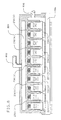
- FIG. 8 is a cross-sectional side view of a thermal conduction module embodying the cooling system described above.
- a liquid dielectric coolant enters the module under pressure through an inlet 802 and flows into a distribution plenum 804. From the distribution plenum 804 the coolant flows down into the cylindrical ducts 230(1)-230(5) and impinges directly on the chips 204(1)-204(5) and flows over the feet of the pistons 210(1)-212(5). After picking up heat from the semi-conductor chips and the pistons, the coolant exits the module through an outlet 806.
- FIGS. 4 and 5 depict an alternative embodiment of the piston arrangement of FIGS. 2 and 3.
- the coolant is delivered to the top of the pistons 410, 412 through cylindrical ducts 402, 404 which are formed in the hat 408 over the center of each of the pistons 410, 412.
- the coolant impinges on the tops of the pistons 410, 412. This provides convective cooling of the upper portion of the pistons.
- the coolant flows down the gaps 414, 416 between the pistons and the piston openings.
- the coolant then impinges on the piston headers and onto the exposed surface of the chip 204 through channels 502, 504 (FIG. 5) formed by the piston headers. This provides convective cooling of the lower portions of the pistons and the chip.
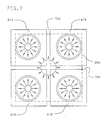
- FIGs. 6 and 7 Yet another embodiment of the piston arrangements, depicted in FIGs. 6 and 7 includes coolant flow to both the top of each piston and the center of each piston cluster.
- the coolant flows through a set of cylindrical ducts 602, 604 centered above each of the pistons 612, 614 and through another cylindrical duct 606 formed in the hat material between the pistons.
- the coolant impinges directly on the pistons 612-618 and also on the chip 204 in the center of the channels 702, 704 formed by the piston headers.
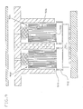
- FIG. 9 is a cross sectional side view of a piston cluster according to the present invention wherein the pistons 902, 904 include an upper cylindrically shaped portion 906 having longitudinally disposed microfins 908 and a rectangular chip contacting header 910 having microfins 912 disposed around the perimeter.
- FIGs. 10A & 10B are, respectively, top and side views of an embodiment of a piston 1000 according to the present invention, having longitudinal upper piston microfins 1002 covering the upper portion of the piston and no microfins on the header.
- longitudinal microfins can be provided on the inner walls of the openings in the hat that receive the pistons.
- the longitudinal microfins are preferably disposed to mesh with those on the upper portion of the pistons, thus increasing the surface area for heat transfer as the coolant passes through the meshed area.
- FIGS. 11A & 11B are, respectively, top and side views of an embodiment of a piston 1100 according to the present invention, having a staggered array of diamond shaped microfins 1102 covering the upper portion of the piston.
- FIGS. 12A & 12B are, respectively, top and side views of yet another embodiment of a piston 1200 according to the present invention, having a staggered array of brick shaped microfins 1202 covering the upper portion of the piston.
- the principles described above can be used to customise cooling from one chip to another or on a single chip.
- the heat dissipated by neighboring chips may vary significantly.
- the chip to chip temperature variation is, however, preferably kept small. It is therefore advantageous to customize cooling by reducing the cooling for low power chips and increasing the cooling for high power chips.
- FIGS. 2-8 can be modified in a variety of ways.
- the points of entry for flow to the piston cluster may be varied. No flow might be necessary for a very low power chip.
- the highest power chips may require coolant delivered to the center of each cluster as well as the top of each piston.
- either one of the cluster centered jets or piston centered jets may be sufficient for many chips.
- the flow delivered to each jet may be varied by, for example, varying the diameter of the cylindrical ducts.
- the selection of piston material will effect cooling.
- a copper piston for example, might be deployed over high power chips.
- microfins can be provided on either the header or the upper portion of the piston, on both the header and the upper portion of the piston, or not at all.
- the present invention is also well suited to customization to maintain a uniform temperature across a single chip. This can be accomplished by taking advantage of the same mechanisms for cooling customization listed above. Instead of varying the controlling parameters from chip to chip, they would be varied from piston to piston so that more or less power can be dissipated at the same chip temperature over all regions of the chip.
- the cylindrical ducts which supply the coolant jet to a given array could each be of a different diameter, or the pistons within each array could be made of materials having different amounts of thermal conductivity.
Landscapes
- Cooling Or The Like Of Semiconductors Or Solid State Devices (AREA)
- Cooling Or The Like Of Electrical Apparatus (AREA)
Applications Claiming Priority (2)
| Application Number | Priority Date | Filing Date | Title |
|---|---|---|---|
| US07/510,756 US5097385A (en) | 1990-04-18 | 1990-04-18 | Super-position cooling |
| US510756 | 1990-04-18 |
Publications (1)
| Publication Number | Publication Date |
|---|---|
| EP0452664A1 true EP0452664A1 (fr) | 1991-10-23 |
Family
ID=24032062
Family Applications (1)
| Application Number | Title | Priority Date | Filing Date |
|---|---|---|---|
| EP91103579A Withdrawn EP0452664A1 (fr) | 1990-04-18 | 1991-03-08 | Module de refroidissement pour circuit électronique |
Country Status (3)
| Country | Link |
|---|---|
| US (1) | US5097385A (fr) |
| EP (1) | EP0452664A1 (fr) |
| JP (1) | JPH0760954B2 (fr) |
Families Citing this family (33)
| Publication number | Priority date | Publication date | Assignee | Title |
|---|---|---|---|---|
| EP0516478A2 (fr) * | 1991-05-30 | 1992-12-02 | Nec Corporation | Structure de refroidissement pour circuits intégrés |
| JPH05136305A (ja) * | 1991-11-08 | 1993-06-01 | Hitachi Ltd | 発熱体の冷却装置 |
| US5241131A (en) * | 1992-04-14 | 1993-08-31 | International Business Machines Corporation | Erosion/corrosion resistant diaphragm |
| GB2268751B (en) * | 1992-07-14 | 1996-01-24 | Suk Jae Oho | Refrigerant comprising liquid nitrogen, polyhydroxy alcohol, aqueous sodium chloride and surfactant |
| JPH06349989A (ja) * | 1992-12-21 | 1994-12-22 | Internatl Business Mach Corp <Ibm> | 熱伝達冷却装置 |
| US5777259A (en) * | 1994-01-14 | 1998-07-07 | Brush Wellman Inc. | Heat exchanger assembly and method for making the same |
| CA2140311A1 (fr) * | 1994-01-14 | 1995-07-15 | Joseph P. Mennucci | Lamelle multicouche et son procede de fabrication |
| US6022426A (en) * | 1995-05-31 | 2000-02-08 | Brush Wellman Inc. | Multilayer laminate process |
| JPH09223883A (ja) * | 1996-02-16 | 1997-08-26 | Hitachi Ltd | 電子機器の冷却装置 |
| US5825087A (en) * | 1996-12-03 | 1998-10-20 | International Business Machines Corporation | Integral mesh flat plate cooling module |
| US5907473A (en) * | 1997-04-04 | 1999-05-25 | Raytheon Company | Environmentally isolated enclosure for electronic components |
| US5944093A (en) * | 1997-12-30 | 1999-08-31 | Intel Corporation | Pickup chuck with an integral heat pipe |
| US6214647B1 (en) | 1998-09-23 | 2001-04-10 | International Business Machines Corporation | Method for bonding heatsink to multiple-height chip |
| US6867976B2 (en) * | 2002-02-12 | 2005-03-15 | Hewlett-Packard Development Company, L.P. | Pin retention for thermal transfer interfaces, and associated methods |
| US20030150605A1 (en) * | 2002-02-12 | 2003-08-14 | Belady Christian L. | Thermal transfer interface system and methods |
| US7035104B2 (en) * | 2002-08-06 | 2006-04-25 | Mudawar Thermal Systems Inc. | Apparatus for heat transfer and critical heat flux enhancement |
| US6890618B2 (en) * | 2002-09-10 | 2005-05-10 | Tyco Electronics Corporation | Method and apparatus for retaining a thermally conductive pin in a thermal spreader plate |
| US6945054B1 (en) | 2002-10-04 | 2005-09-20 | Richard S. Norman | Method and apparatus for cooling microelectronic complexes including multiple discrete functional modules |
| US6906924B2 (en) * | 2003-05-16 | 2005-06-14 | Hewlett-Packard Development Company, L.P. | Temperature-controlled rework system |
| US7280363B2 (en) * | 2005-01-21 | 2007-10-09 | Delphi Technologies, Inc. | Apparatus for controlling thermal interface between cold plate and integrated circuit chip |
| US7212409B1 (en) | 2005-12-05 | 2007-05-01 | Hewlett-Packard Development Company, L.P. | Cam actuated cold plate |
| US7536870B2 (en) * | 2006-03-30 | 2009-05-26 | International Business Machines Corporation | High power microjet cooler |
| JP4533938B2 (ja) * | 2008-04-09 | 2010-09-01 | 新太郎 後藤 | 足踏み式エアコンプレッサ |
| US20110232882A1 (en) * | 2010-03-29 | 2011-09-29 | Zaffetti Mark A | Compact cold plate configuration utilizing ramped closure bars |
| US8869877B2 (en) | 2010-10-11 | 2014-10-28 | Hamilton Sundstrand Space Systems International, Inc. | Monolithic cold plate configuration |
| SG181180A1 (en) * | 2010-11-12 | 2012-06-28 | Semicaps Pte Ltd | Apparatus and method for cooling a semiconductor device |
| US8592970B2 (en) * | 2011-06-27 | 2013-11-26 | International Business Machines Corporation | Multichip electronic packages and methods of manufacture |
| US9917034B2 (en) | 2014-09-26 | 2018-03-13 | Semicaps Pte Ltd | Method and apparatus for cooling a semiconductor device |
| US9659838B1 (en) * | 2016-03-28 | 2017-05-23 | Lockheed Martin Corporation | Integration of chip level micro-fluidic cooling in chip packages for heat flux removal |
| US10881019B2 (en) * | 2018-03-09 | 2020-12-29 | Fujitsu Limited | Cooling apparatus |
| US20220015262A1 (en) * | 2020-07-09 | 2022-01-13 | Intel Corporation | Technologies for dynamic cooling in a multi-chip package with programmable impingement valves |
| US11240934B1 (en) * | 2020-07-22 | 2022-02-01 | TE Connectivity Services Gmbh | Thermal bridge for an electrical component |
| US20220238413A1 (en) * | 2021-01-22 | 2022-07-28 | Infineon Technologies Ag | Double sided cooling module with power transistor submodules |
Citations (2)
| Publication number | Priority date | Publication date | Assignee | Title |
|---|---|---|---|---|
| EP0341950A2 (fr) * | 1988-05-09 | 1989-11-15 | Nec Corporation | Structure de refroidissement plane d'un circuit intégré |
| US4928207A (en) * | 1989-06-15 | 1990-05-22 | International Business Machines Corporation | Circuit module with direct liquid cooling by a coolant flowing between a heat producing component and the face of a piston |
Family Cites Families (10)
| Publication number | Priority date | Publication date | Assignee | Title |
|---|---|---|---|---|
| US4138692A (en) * | 1977-09-12 | 1979-02-06 | International Business Machines Corporation | Gas encapsulated cooling module |
| US4203129A (en) * | 1978-07-11 | 1980-05-13 | International Business Machines Corporation | Bubble generating tunnels for cooling semiconductor devices |
| US4277816A (en) * | 1979-05-29 | 1981-07-07 | International Business Machines Corporation | Electronic circuit module cooling |
| US4226281A (en) * | 1979-06-11 | 1980-10-07 | International Business Machines Corporation | Thermal conduction module |
| US4296455A (en) * | 1979-11-23 | 1981-10-20 | International Business Machines Corporation | Slotted heat sinks for high powered air cooled modules |
| US4291364A (en) * | 1979-12-26 | 1981-09-22 | International Business Machines Corporation | Air-cooled hybrid electronic package |
| DE3028632C2 (de) * | 1980-07-29 | 1985-07-25 | Wilhelm Gebhardt Gmbh, 7112 Waldenburg | Regenerator mit einer in einem Gehäuse untergebrachten, um eine Drehachse umlaufenden, hohlzylindrischen Wärmetauscherwalze |
| US4561040A (en) * | 1984-07-12 | 1985-12-24 | Ibm Corporation | Cooling system for VLSI circuit chips |
| US4800956A (en) * | 1986-04-25 | 1989-01-31 | Digital Equipment Corporation | Apparatus and method for removal of heat from packaged element |
| US4951740A (en) * | 1988-06-27 | 1990-08-28 | Texas A & M University System | Bellows heat pipe for thermal control of electronic components |
-
1990
- 1990-04-18 US US07/510,756 patent/US5097385A/en not_active Expired - Fee Related
-
1991
- 1991-03-08 EP EP91103579A patent/EP0452664A1/fr not_active Withdrawn
- 1991-03-18 JP JP3052434A patent/JPH0760954B2/ja not_active Expired - Lifetime
Patent Citations (2)
| Publication number | Priority date | Publication date | Assignee | Title |
|---|---|---|---|---|
| EP0341950A2 (fr) * | 1988-05-09 | 1989-11-15 | Nec Corporation | Structure de refroidissement plane d'un circuit intégré |
| US4928207A (en) * | 1989-06-15 | 1990-05-22 | International Business Machines Corporation | Circuit module with direct liquid cooling by a coolant flowing between a heat producing component and the face of a piston |
Non-Patent Citations (5)
| Title |
|---|
| IBM TECHNICAL DISCLOSURE BULLETIN, vol. 21, no. 5, October 1978, NEW YORK, US; pages 1858 - 1859; S. OKTAY ET AL.: "SERRATED PISTONS FOR IMPROVED MODULE COOLING" * |
| IBM TECHNICAL DISCLOSURE BULLETIN, vol. 27, no. 12, May 1985, NEW YORK, US; page 6898: "THERMAL CONDUCTION MODULE WITH PISTONS HAVING CHANNELS FOR CARRYING A COOLING LIQUID THAT IS SPRAYED ONTO THE CHIP" * |
| IBM TECHNICAL DISCLOSURE BULLETIN, vol. 31, no. 12, May 1989, NEW YORK, US; pages 5 - 7: "CIRCUIT MODULE COOLING WITH MULTIPLE PISTONS CONTACTING A HEAT SPREADER/ELECTRICAL BUFFER PLATE IN CONTACT WITH THE CHIP" * |
| IBM TECHNICAL DISCLOSURE BULLETIN, vol. 32, no. 9A, February 1990, NEW YORK, US; pages 106 - 107; "MULTI-ORIFICE FLUORCARBON IMPINGEMENT COOLING FOR ARRAYS OF MICROELECTRONIC DEVICES" * |
| RESEARCH DISCLOSURE, no. 301, May 1989, HAVANT, GB; page 350: "TCM WITH MULTIPLE PISTONS IN NON-ORTHOGONAL PATTERN FOR ADDITIONAL SURFACE AREA IN CONTACT WITH CHIP AND SPACE BETWEEN CHIPS FOR COLD PLATE BOLT" * |
Also Published As
| Publication number | Publication date |
|---|---|
| JPH04250698A (ja) | 1992-09-07 |
| JPH0760954B2 (ja) | 1995-06-28 |
| US5097385A (en) | 1992-03-17 |
Similar Documents
| Publication | Publication Date | Title |
|---|---|---|
| US5097385A (en) | Super-position cooling | |
| US5021924A (en) | Semiconductor cooling device | |
| US5023695A (en) | Flat cooling structure of integrated circuit | |
| US5294830A (en) | Apparatus for indirect impingement cooling of integrated circuit chips | |
| KR900002213B1 (ko) | 전자회로장치용 냉각시스템 | |
| US5719444A (en) | Packaging and cooling system for power semi-conductor | |
| US6581388B2 (en) | Active temperature gradient reducer | |
| EP0031448B1 (fr) | Module thermo-conducteur pour microplaquettes à circuit intégré | |
| EP0129966B1 (fr) | Circuit à module avec un refroidissement de grande efficacité | |
| US5696405A (en) | Microelectronic package with device cooling | |
| US6075287A (en) | Integrated, multi-chip, thermally conductive packaging device and methodology | |
| US5436793A (en) | Apparatus for containing and cooling an integrated circuit device having a thermally insulative positioning member | |
| EP0127115B1 (fr) | Structure d'un puits de chaleur pour un empaquetage électronique | |
| KR0121438B1 (ko) | 반도체 장치 | |
| EP0447835A2 (fr) | Dispositif dissipant la chaleur pour modules semi-conducteurs refroidis par un liquide | |
| US4450505A (en) | Apparatus for cooling integrated circuit chips | |
| US4839774A (en) | Apparatus and method for cooling electronic component packages using an array of directed nozzles fabricated in the circuit board | |
| EP0538833A1 (fr) | Empaquetage pour circuit intégré comprenant un mécanisme de refroidissement | |
| JP2894243B2 (ja) | 熱放散特性に優れたヒートシンク | |
| WO2001061751A2 (fr) | Dissipateur thermique en cuivre hybride a plaques paralleles/ailettes tres fines destine au refroidissement d'un microprocesseur tres puissant | |
| WO1981003734A1 (fr) | Conditionnement de circuit integre a dissipateur thermique | |
| EP4184563A1 (fr) | Élément de régulation de température utilisé dans des boîtiers de puces de dispositifs | |
| US20070200226A1 (en) | Cooling micro-channels | |
| EP0123795A2 (fr) | Dissipateur de chaleur d'une seule pièce pour un module de dispositif électronique | |
| EP0167665B1 (fr) | Appareil pour le refroidissement de puces à circuit intégré |
Legal Events
| Date | Code | Title | Description |
|---|---|---|---|
| PUAI | Public reference made under article 153(3) epc to a published international application that has entered the european phase |
Free format text: ORIGINAL CODE: 0009012 |
|
| AK | Designated contracting states |
Kind code of ref document: A1 Designated state(s): DE FR GB IT |
|
| 17P | Request for examination filed |
Effective date: 19911219 |
|
| 17Q | First examination report despatched |
Effective date: 19940406 |
|
| GRAH | Despatch of communication of intention to grant a patent |
Free format text: ORIGINAL CODE: EPIDOS IGRA |
|
| STAA | Information on the status of an ep patent application or granted ep patent |
Free format text: STATUS: THE APPLICATION IS DEEMED TO BE WITHDRAWN |
|
| 18D | Application deemed to be withdrawn |
Effective date: 19960423 |