EP0452669B1 - Amplificateur optique à fibre dopée à l'erbium - Google Patents
Amplificateur optique à fibre dopée à l'erbium Download PDFInfo
- Publication number
- EP0452669B1 EP0452669B1 EP91103677A EP91103677A EP0452669B1 EP 0452669 B1 EP0452669 B1 EP 0452669B1 EP 91103677 A EP91103677 A EP 91103677A EP 91103677 A EP91103677 A EP 91103677A EP 0452669 B1 EP0452669 B1 EP 0452669B1
- Authority
- EP
- European Patent Office
- Prior art keywords
- fiber
- erbium
- optical amplifier
- core
- pump
- Prior art date
- Legal status (The legal status is an assumption and is not a legal conclusion. Google has not performed a legal analysis and makes no representation as to the accuracy of the status listed.)
- Expired - Lifetime
Links
- 239000000835 fiber Substances 0.000 title claims description 48
- 230000003287 optical effect Effects 0.000 title claims description 15
- 229910052691 Erbium Inorganic materials 0.000 title claims description 12
- UYAHIZSMUZPPFV-UHFFFAOYSA-N erbium Chemical compound [Er] UYAHIZSMUZPPFV-UHFFFAOYSA-N 0.000 title claims description 12
- 238000009826 distribution Methods 0.000 claims description 11
- 238000005253 cladding Methods 0.000 claims 1
- 238000001228 spectrum Methods 0.000 claims 1
- 230000003595 spectral effect Effects 0.000 description 8
- 238000005086 pumping Methods 0.000 description 4
- 230000003321 amplification Effects 0.000 description 3
- 230000005540 biological transmission Effects 0.000 description 3
- 238000000034 method Methods 0.000 description 3
- 238000003199 nucleic acid amplification method Methods 0.000 description 3
- 229920000297 Rayon Polymers 0.000 description 2
- 239000013307 optical fiber Substances 0.000 description 2
- 238000005457 optimization Methods 0.000 description 2
- 239000002964 rayon Substances 0.000 description 2
- 238000004458 analytical method Methods 0.000 description 1
- 230000015556 catabolic process Effects 0.000 description 1
- 238000006731 degradation reaction Methods 0.000 description 1
- 230000006866 deterioration Effects 0.000 description 1
- 238000010586 diagram Methods 0.000 description 1
- 230000004807 localization Effects 0.000 description 1
- 238000009827 uniform distribution Methods 0.000 description 1
Images
Classifications
-
- H—ELECTRICITY
- H01—ELECTRIC ELEMENTS
- H01S—DEVICES USING THE PROCESS OF LIGHT AMPLIFICATION BY STIMULATED EMISSION OF RADIATION [LASER] TO AMPLIFY OR GENERATE LIGHT; DEVICES USING STIMULATED EMISSION OF ELECTROMAGNETIC RADIATION IN WAVE RANGES OTHER THAN OPTICAL
- H01S3/00—Lasers, i.e. devices using stimulated emission of electromagnetic radiation in the infrared, visible or ultraviolet wave range
- H01S3/05—Construction or shape of optical resonators; Accommodation of active medium therein; Shape of active medium
- H01S3/06—Construction or shape of active medium
- H01S3/063—Waveguide lasers, i.e. whereby the dimensions of the waveguide are of the order of the light wavelength
- H01S3/067—Fibre lasers
- H01S3/06708—Constructional details of the fibre, e.g. compositions, cross-section, shape or tapering
Definitions
- the present invention relates to an optical amplifier of erbium-doped fiber, finding in particular an application in underwater telecommunications systems with optical fibers.
- erbium-doped optical fiber amplifiers lies in obtaining high gains by simply passing the signal, in the spectral range 1.5 - 1.6 ⁇ m, for reduced pumping optical powers, of the order from 1 to 150 mW.
- the stability of the amplification process in a fiber is inter alia linked to the modal noises of the optical pump. It is therefore preferable for the amplifier to operate according to a principle diagram in which the optical pump and the signal to be amplified are single-mode, the cut-off wavelength of the LP11 mode of the amplifying fiber being thus less than the wavelength of the pump. This restricts the pumping wavelengths to the two spectral ranges 0.98 ⁇ 0.04 ⁇ m and 1.48 ⁇ 0.04 ⁇ m.
- An analysis of the efficiency of the processes governing the amplifiers can be carried out by analyzing the gain coefficient g obtained by the ratio between the net gain G, expressed in dB, of the amplifying fiber and the optical pumping power, expressed in mW. This coefficient is thus expressed in dB / mW.
- the second indicates a gain coefficient g of 4.9 dB / mW for a pump power of 5mW located in the spectral range of 0.98 ⁇ m; the fiber has a mode radius w o at the wavelength of 1.55 ⁇ m equal to 2.99 ⁇ m. Neither of these articles specifies the radial distribution of erbium in the fiber.
- the object of the present invention is to produce optical amplifiers whose amplifying fibers have performances, and therefore gain coefficients, greater than those currently known.
- the present invention proposes an optimization of the parameters of the fiber and an optimization of the radial localization of erbium.
- an amplifier according to the invention has a gain coefficient g which can reach higher values. at 5 dB / mW without significant degradation of this signal to noise ratio.
- the gain coefficient g of said fiber is improved by a reduction in the required pump power threshold to have a gain of 0 dB over an optimal length of the amplifying fiber. In fact, this coefficient is all the more important as high gains are obtained for low pump powers. However, this threshold is improved by an increase in the optical power density of the pump, therefore by a reduction in the mode radius at the pump wavelength and also at the signal wavelength.
- the core radius R of the fiber is between 1.2 ⁇ m and 1.6 ⁇ m; it is for example equal to 1.5 ⁇ m.
- the difference in index ⁇ n between the core and the sheath of the fiber is for example equal to 30x10 ⁇ 3.
- fiber No. 1 is a fiber according to the invention and fiber No. 2 is a fiber not forming part of the invention.
- the profile of the erbium distribution ⁇ is defined by its width at mid-height r equal to one fifth of the radius of the core R of the fiber.
- the central position of the doped zone coincides with the maximum energy of the fundamental mode of the pump.
- Fiber # 2 has a uniform distribution of erbium in its core.
- Table I below gives results for these two fibers corresponding to a pump power of 5 mW at 1.476 ⁇ m with an incident signal of 0.1 ⁇ W at 1.532 ⁇ m.
- Table I Fiber # 1 Fiber # 2 L (m) 24 22 ⁇ n 30x10 ⁇ 3 30x10 ⁇ 3 R ( ⁇ m) 1.5 1.5 wo ( ⁇ m) 2.1 2.1 G (dB) 27.4 22.6 g (dB / mW) 5.5 4.5
- an amplifier according to the invention has, for weak incident signals, a significantly improved gain coefficient and, for signals strong enough to correspond to the amplification saturation regime, an overall efficiency of the greatly improved amplification process.
- Amplifiers designed according to the present invention could for example work at low saturation power with significant gains, which is advantageous for an amplifier inserted in a transmission line.
- a fiber according to the invention can be produced for example from a preform obtained in accordance with the teaching of French patent BF 2,621,909.
- the invention is not limited to the examples described, in particular with regard to the curve of radial distribution of erbium in the fiber, the values of the core radius and of the index difference ⁇ n.
Landscapes
- Physics & Mathematics (AREA)
- Electromagnetism (AREA)
- Engineering & Computer Science (AREA)
- Plasma & Fusion (AREA)
- Optics & Photonics (AREA)
- Lasers (AREA)
- Optical Communication System (AREA)
- Optical Fibers, Optical Fiber Cores, And Optical Fiber Bundles (AREA)
- Light Guides In General And Applications Therefor (AREA)
Description
- La présente invention concerne un amplificateur optique à fibre dopée à l'erbium, trouvant notamment une application dans les systèmes de télécommunications sous-marines à fibres optiques.
- La particularité des amplificateurs à fibre optique dopée à l'erbium réside dans l'obtention de gains élevés par simple passage du signal, dans le domaine spectral 1,5 - 1,6µm, pour des puissances optiques de pompage réduites, de l'ordre de 1 à 150 mW.
- La stabilité du processus d'amplification dans une fibre est entre autres liée aux bruits modaux de la pompe optique. Il est donc préférable que l'amplificateur fonctionne suivant un schéma de principe dans lequel la pompe optique et le signal à amplifier sont monomodes, la longueur d'onde de coupure du mode LP₁₁ de la fibre amplificatrice étant ainsi inférieure à la longueur d'onde de la pompe. Cela restreint les longueurs d'ondes de pompage aux deux domaines spectraux 0,98±0,04µm et 1,48±0,04µm.
- Une analyse de l'efficacité des processus régissant les amplificateurs peut être conduite en analysant le coefficient de gain g obtenu par le rapport entre le gain net G, exprimé en dB, de la fibre amplificatrice et la puissance optique de pompage, exprimée en mW. Ce coefficient s'exprime ainsi en dB/mW.
- Les amplificateurs optiques connus pour avoir les meilleures performances sont décrits dans les deux articles suivants :
- [1] J.L. ZYSKIND, J.R.SIMPSON, C.R.GILES and E.DESURVIRE, SPIE, vol. 1171 "Files Laser Sources and Amplifiers", pages 137-145, Conférence SPIE, Boston (USA), Septembre 1989.
- [2] M. SHIMIZU, M. HORIGUCHI, M.YAMADA, I. MISHI, S. UEHARA, J. NODA, E. SUGITA, Post-deadline paper n° 17, OFC Conférence, San Francisco (USA), January 1990.
- Le premier divulgue un coefficient de gain g de 2,6 dB/mW pour une puissance de pompe de 10mW située dans le domaine spectral de 1,48µm ; la fibre correspondante présente un rayon de mode wo à la longueur d'onde de 1,55µm égal à 2,71µm.
- Le second indique un coefficient de gain g de 4,9 dB/mW pour une puissance de pompe de 5mW située dans le domaine spectral de 0,98µm ; la fibre présente un rayon de mode wo à la longueur d'onde de 1,55µm égal à 2,99 µm. Aucun de ces deux articles ne précise la distribution radiale de l'erbium dans la fibre.
- La présente invention a pour but de réaliser des amplificateurs optiques dont les fibres amplificatrices présentent des performances, et donc des coefficients de gain, supérieurs à ceux actuellement connus. Pour y parvenir, la présente invention propose une optimisation des paramètres de la fibre et une optimisation de la localisation radiale de l'erbium.
- La présente invention a pour objet un amplificateur optique à fibre dopée à l'erbium destiné à amplifier des signaux de longueur d'onde comprise entre 1,5 µm et 1,6 µm, et associé à une pompe optique, caractérisé par le fait que :
- ladite fibre présente un rayon de mode inférieur ou égal à 2,7 µm à la longueur d'onde de 1,55 µm,
- l'écart d'indice Δn entre le coeur et la gaine de la fibre est compris entre 25x10⁻³ et 35x10⁻³,
- l'erbium est localisé dans le coeur de ladite fibre de façon que sa distribution radiale soit centrée sur l'axe de révolution de cette fibre avec une largeur à mi-hauteur de ladite distribution inférieure au tiers du rayon de coeur,
- la longueur d'onde de pompe est située dans les domaines spectraux de 0,98 ± 0,04 µm ou de 1,48 ± 0,04 µm,
- le coefficient de gain g, égal au rapport entre le gain net G (mesuré en dB) et la puissance de pompe (mesurée en mW), est supérieur à 5 dB/mW.
- De manière étonnante, alors qu'on pouvait s'attendre à une dégradation du rapport signal à bruit due à la réduction du rayon de mode, on constate qu'un amplificateur selon l'invention présente un coefficient de gain g pouvant atteindre des valeurs supérieures à 5 dB/mW sans dégradation notable de ce rapport signal à bruit.
- Le coefficient de gain g de ladite fibre est amélioré par une diminution du seuil de puissance de pompe nécessaire pour avoir un gain de 0 dB sur une longueur optimale de la fibre amplificatrice. En effet, ce coefficient est d'autant plus important que l'on obtient des gains élevés pour de faibles puissances de pompe. Or, ce seuil est amélioré par une augmentation de la densité de puissance optique de la pompe, donc par une réduction du rayon de mode à la longueur d'onde de pompe et aussi à la longueur d'onde signal.
- Des auteurs tels que J.R. ARMITAGE dans un article paru dans "Applied Optics, 27, 1988 pages 4831 à 4836" qui ont déjà essayé d'optimiser les paramètres de la fibre de l'amplificateur n'ont pas mis en évidence le rôle primordial du rayon de mode wo.
- Selon un mode de réalisation préférentiel, le rayon de coeur R de la fibre est compris entre 1,2 µm et 1,6 µm ; il est par exemple égal à 1,5 µm.
- L'écart d'indice Δn entre le coeur et la gaine de la fibre est par exemple égal à 30x10⁻³.
- D'autres caractéristiques et avantages de la présente invention apparaîtront au cours de la description suivante de modes de réalisation donnés à titre illustratif mais nullement limitatif.
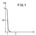
- Dans le dessin annexé, la figure unique montre la distribution radiale ρ de l'erbium dans un exemple de fibre selon l'invention.
- On étudie deux amplificateurs à fibre : la fibre n° 1 est une fibre selon l'invention et la fibre n° 2 est une fibre ne faisant pas partie de l'invention.
- On a reporté dans le tableau I leur longueur optimale L (mètres), la valeur de leur écart d'indice Δn, leur rayon de coeur R (µm), leur rayon de mode wo (µm), leur gain G (dB) et leur coefficient de gain g (dB/mW).
- On prévoit une distribution radiale non uniforme de l'erbium dans la fibre n° 1, par exemple conformément à la figure unique. Le profil de la distribution d'erbium ρ est défini par sa largeur à mi-hauteur r égale au cinquième du rayon du coeur R de la fibre. La position centrale de la zone dopée coïncide avec le maximum d'énergie du mode fondamental de la pompe.
- La fibre n° 2 a une distribution uniforme d'erbium dans son coeur.
- Le tableau I ci-dessous donne des résultats pour ces deux fibres correspondant à une puissance de pompe de 5 mW à 1,476 µm avec un signal incident de 0,1 µW à 1,532 µm.
Tableau I Fibre n° 1 Fibre n° 2 L (m) 24 22 Δn 30x10⁻³ 30x10⁻³ R (µm) 1,5 1,5 wo (µm) 2,1 2,1 G (dB) 27,4 22,6 g (dB/mW) 5,5 4,5 - On obtient avec la fibre n° 1 un coefficient de gain g supérieur à 5 dB/mW.
- Par rapport aux amplificateurs de l'art antérieur, un amplificateur selon l'invention présente, pour les faibles signaux incidents, un coefficient de gain nettement amélioré et, pour des signaux assez forts pour correspondre au régime de saturation d'amplification, un rendement global du processus d'amplification très amélioré.
- Des amplificateurs conçus suivant la présente invention pourraient par exemple travailler à faible puissance de saturation avec des gains importants, ce qui est intéressant pour un amplificateur inséré dans une ligne de transmission.
- L'amélioration des performances d'un amplificateur selon l'invention apparaît donc quel que soit son régime de fonctionnement avec :
- un pompage dans les domaines spectraux de 0,98 ± 0,04 µm et 1,48 µm ± 0,04 µm,
- des signaux incidents sur la fibre faibles ou forts à des longueurs d'onde comprises dans le domaine spectral 1,5 µm-1,6 µm,
- une position quelconque de l'amplificateur sur la ligne de transmission.
- Une fibre selon l'invention peut être réalisée par exemple à partir d'une préforme obtenue conformément à l'enseignement du brevet français BF 2 621 909.
- Bien entendu l'invention n'est pas limitée aux exemples décrits, notamment en ce qui concerne la courbe de répartition radiale de l'erbium dans la fibre, les valeurs du rayon de coeur et de l'écart d'indice Δn.
Claims (3)
- Amplificateur optique à fibre dopée à l'erbium destiné à amplifier des signaux de longueur d'onde comprise entre 1,5 µm et 1,6 µm, et associé à une pompe optique, caractérisé par le fait que :- ladite fibre présente un rayon de mode inférieur ou égal à 2,7 µm à la longueur d'onde de 1,55 µm,- l'écart d'indice Δn entre le coeur et la gaine de la fibre est compris entre 25x10⁻³ et 35x10⁻³,- l'erbium est localisé dans le coeur de ladite fibre de façon que sa distribution radiale soit centrée sur l'axe de révolution de cette fibre avec une largeur à mi-hauteur de ladite distribution inférieure au tiers du rayon de coeur,- la longueur d'onde de pompe est située dans les domaines spectraux de 0,98 ± 0,04 µm ou de 1,48 ± 0,04 µm,- le coefficient de gain g, égal au rapport entre le gain net G (mesuré en dB) et la puissance de pompe (mesurée en mW), est supérieur à 5 dB/mW.
- Amplificateur optique à fibre dopée à l'erbium selon la revendication 1, caractérisé par le fait que le rayon du coeur de ladite fibre est compris entre 1,2 µm et 1,6 µm.
- Amplificateur optique à fibre dopée à l'erbium selon la revendication 2, caractérisé par le fait que ledit rayon de coeur est égal à 1,5 µm et ledit écart d'indice Δn est égal à 30x10⁻³.
Applications Claiming Priority (2)
| Application Number | Priority Date | Filing Date | Title |
|---|---|---|---|
| FR9003399 | 1990-03-16 | ||
| FR9003399A FR2659755B1 (fr) | 1990-03-16 | 1990-03-16 | Amplificateur optique a fibre dopee a l'erbium. |
Publications (2)
| Publication Number | Publication Date |
|---|---|
| EP0452669A1 EP0452669A1 (fr) | 1991-10-23 |
| EP0452669B1 true EP0452669B1 (fr) | 1996-02-21 |
Family
ID=9394825
Family Applications (1)
| Application Number | Title | Priority Date | Filing Date |
|---|---|---|---|
| EP91103677A Expired - Lifetime EP0452669B1 (fr) | 1990-03-16 | 1991-03-11 | Amplificateur optique à fibre dopée à l'erbium |
Country Status (6)
| Country | Link |
|---|---|
| US (1) | US5134517A (fr) |
| EP (1) | EP0452669B1 (fr) |
| JP (1) | JP2612975B2 (fr) |
| AU (1) | AU642470B2 (fr) |
| CA (1) | CA2038329C (fr) |
| FR (1) | FR2659755B1 (fr) |
Families Citing this family (7)
| Publication number | Priority date | Publication date | Assignee | Title |
|---|---|---|---|---|
| US5337375A (en) * | 1992-12-31 | 1994-08-09 | At&T Bell Laboratories | Depolarizer using unpumped, doped optical fiber and method using same |
| JP3299684B2 (ja) | 1997-04-23 | 2002-07-08 | 日本電信電話株式会社 | 光増幅器および光増幅方法 |
| FR2805899B1 (fr) * | 2000-03-03 | 2003-01-31 | Cit Alcatel | Amplification optique a fibre a gaine multimode en bande c |
| US7065302B1 (en) | 2000-09-15 | 2006-06-20 | Lockheed Martin Corporation | High efficiency optical feedback modulator and method of operation |
| JP4947853B2 (ja) * | 2001-06-25 | 2012-06-06 | 三菱電線工業株式会社 | 希土類元素ドープファイバ |
| EP1586144B1 (fr) * | 2003-01-24 | 2016-05-11 | Trumpf, Inc. | Laser a fibre |
| US8611002B2 (en) * | 2009-09-24 | 2013-12-17 | Gavin P. Frith | Optical fiber lasers and amplifiers and methods for providing optical gain |
Citations (2)
| Publication number | Priority date | Publication date | Assignee | Title |
|---|---|---|---|---|
| EP0430515A2 (fr) * | 1989-11-27 | 1991-06-05 | AT&T Corp. | Amplificateur à fibre optique dopée avec de l'erbium |
| EP0437935A2 (fr) * | 1990-01-19 | 1991-07-24 | AT&T Corp. | Amplificateur à fibre dopée à l'erbium |
Family Cites Families (4)
| Publication number | Priority date | Publication date | Assignee | Title |
|---|---|---|---|---|
| US3950707A (en) * | 1973-04-13 | 1976-04-13 | Canadian Patents And Development Limited | Quantum amplifier having passive core and active cladding providing signal gain by interaction of evanescent-wave components of signal and pump beams propagating along the core |
| FR2621909B1 (fr) * | 1987-10-16 | 1990-01-19 | Comp Generale Electricite | |
| GB8724736D0 (en) * | 1987-10-22 | 1987-11-25 | British Telecomm | Optical fibre |
| IT1237980B (it) * | 1990-02-12 | 1993-06-19 | Pirelli Cavi Spa | Amplificatore ottico a fibra attiva monomodale incurvata |
-
1990
- 1990-03-16 FR FR9003399A patent/FR2659755B1/fr not_active Expired - Lifetime
-
1991
- 1991-03-06 US US07/665,533 patent/US5134517A/en not_active Expired - Lifetime
- 1991-03-08 AU AU72770/91A patent/AU642470B2/en not_active Ceased
- 1991-03-11 EP EP91103677A patent/EP0452669B1/fr not_active Expired - Lifetime
- 1991-03-15 CA CA002038329A patent/CA2038329C/fr not_active Expired - Fee Related
- 1991-03-15 JP JP3075729A patent/JP2612975B2/ja not_active Expired - Fee Related
Patent Citations (2)
| Publication number | Priority date | Publication date | Assignee | Title |
|---|---|---|---|---|
| EP0430515A2 (fr) * | 1989-11-27 | 1991-06-05 | AT&T Corp. | Amplificateur à fibre optique dopée avec de l'erbium |
| EP0437935A2 (fr) * | 1990-01-19 | 1991-07-24 | AT&T Corp. | Amplificateur à fibre dopée à l'erbium |
Also Published As
| Publication number | Publication date |
|---|---|
| JP2612975B2 (ja) | 1997-05-21 |
| AU7277091A (en) | 1991-09-26 |
| AU642470B2 (en) | 1993-10-21 |
| US5134517A (en) | 1992-07-28 |
| CA2038329C (fr) | 1995-06-13 |
| JPH04221870A (ja) | 1992-08-12 |
| EP0452669A1 (fr) | 1991-10-23 |
| FR2659755A1 (fr) | 1991-09-20 |
| FR2659755B1 (fr) | 1992-05-29 |
Similar Documents
| Publication | Publication Date | Title |
|---|---|---|
| EP0368196B1 (fr) | Amplificateur laser à fibre optique dopée | |
| JP2734209B2 (ja) | 光ファイバ増幅器 | |
| FR2782851A1 (fr) | Amplificateur a fibres optiques a longue bande a rendement de conversion d'energie ameliore | |
| FR2765752A1 (fr) | Amplificateur a fibre optique pour atteindre un gain eleve d'un petit signal | |
| US6433927B1 (en) | Low cost amplifier using bulk optics | |
| FR2782199A1 (fr) | Amplificateur a fibre optique a grande longueur d'onde | |
| Maes et al. | High power BDF/EDF hybrid amplifier providing 27 dB gain over 90 nm in the E+ S band | |
| EP0452669B1 (fr) | Amplificateur optique à fibre dopée à l'erbium | |
| Khegai et al. | O+ E band BDFA with flattop 116 nm gain bandwidth pumped with 250 mW at 1256 nm | |
| EP0704945B1 (fr) | Amplificateur optique régulé à circulateur optique | |
| FR2749724A1 (fr) | Filtre optique et systeme de transmission optique le comportant | |
| CN1081838C (zh) | 光纤放大器 | |
| FR3073953A1 (fr) | Fibre optique et reseau de fibres incline | |
| CN1175315C (zh) | 低噪声、高增益、高平坦的长波段掺铒光纤放大器 | |
| EP0508880B1 (fr) | Amplificateur optique à fibre optique dopée à l'erbium | |
| EP0957545B1 (fr) | Fibre optique pour amplificateur optique à gain plat | |
| Abdullah et al. | Influence of Raman pump direction on the performance of serial hybrid fiber amplifier in C+ L-band | |
| FR2790105A1 (fr) | Systeme, ligne et procede de transmission a fibre optique | |
| EP1087475B1 (fr) | Amplificateur à fibre optique en bande L | |
| CN120255234B (zh) | 激光强度低通滤波方法和装置 | |
| FR2767996A1 (fr) | Amplificateur d'impulsions optiques | |
| EP1696523B1 (fr) | Amplificateur optique à diffusion raman | |
| Maes et al. | High power BDF/EDF hybrid amplifier providing 27 dB gain over 90 nm in the $\mathrm {E}+\mathrm {S} $ band | |
| Markom et al. | 50 cm of zirconia, bismuth and silica erbium-doped fibers for double-pass amplification with a broadband mirror | |
| JPH0410586A (ja) | 光ファイバ増幅器 |
Legal Events
| Date | Code | Title | Description |
|---|---|---|---|
| PUAI | Public reference made under article 153(3) epc to a published international application that has entered the european phase |
Free format text: ORIGINAL CODE: 0009012 |
|
| AK | Designated contracting states |
Kind code of ref document: A1 Designated state(s): DE FR GB IT NL SE |
|
| 17P | Request for examination filed |
Effective date: 19920422 |
|
| 17Q | First examination report despatched |
Effective date: 19930705 |
|
| RBV | Designated contracting states (corrected) |
Designated state(s): IT NL SE |
|
| REG | Reference to a national code |
Ref country code: DE Ref legal event code: 8566 |
|
| GRAA | (expected) grant |
Free format text: ORIGINAL CODE: 0009210 |
|
| AK | Designated contracting states |
Kind code of ref document: B1 Designated state(s): IT NL SE |
|
| ITF | It: translation for a ep patent filed | ||
| PLBE | No opposition filed within time limit |
Free format text: ORIGINAL CODE: 0009261 |
|
| STAA | Information on the status of an ep patent application or granted ep patent |
Free format text: STATUS: NO OPPOSITION FILED WITHIN TIME LIMIT |
|
| 26N | No opposition filed | ||
| PGFP | Annual fee paid to national office [announced via postgrant information from national office to epo] |
Ref country code: IT Payment date: 20080321 Year of fee payment: 18 Ref country code: NL Payment date: 20080318 Year of fee payment: 18 Ref country code: SE Payment date: 20080313 Year of fee payment: 18 |
|
| EUG | Se: european patent has lapsed | ||
| NLV4 | Nl: lapsed or anulled due to non-payment of the annual fee |
Effective date: 20091001 |
|
| PG25 | Lapsed in a contracting state [announced via postgrant information from national office to epo] |
Ref country code: NL Free format text: LAPSE BECAUSE OF NON-PAYMENT OF DUE FEES Effective date: 20091001 |
|
| PG25 | Lapsed in a contracting state [announced via postgrant information from national office to epo] |
Ref country code: IT Free format text: LAPSE BECAUSE OF NON-PAYMENT OF DUE FEES Effective date: 20090311 |
|
| PG25 | Lapsed in a contracting state [announced via postgrant information from national office to epo] |
Ref country code: SE Free format text: LAPSE BECAUSE OF NON-PAYMENT OF DUE FEES Effective date: 20090312 |