EP0452674A1 - Chariot de nettoyage - Google Patents
Chariot de nettoyage Download PDFInfo
- Publication number
- EP0452674A1 EP0452674A1 EP91103798A EP91103798A EP0452674A1 EP 0452674 A1 EP0452674 A1 EP 0452674A1 EP 91103798 A EP91103798 A EP 91103798A EP 91103798 A EP91103798 A EP 91103798A EP 0452674 A1 EP0452674 A1 EP 0452674A1
- Authority
- EP
- European Patent Office
- Prior art keywords
- cleaning trolley
- trolley according
- central strut
- side brackets
- cross struts
- Prior art date
- Legal status (The legal status is an assumption and is not a legal conclusion. Google has not performed a legal analysis and makes no representation as to the accuracy of the status listed.)
- Granted
Links
Images


Classifications
-
- B—PERFORMING OPERATIONS; TRANSPORTING
- B62—LAND VEHICLES FOR TRAVELLING OTHERWISE THAN ON RAILS
- B62B—HAND-PROPELLED VEHICLES, e.g. HAND CARTS OR PERAMBULATORS; SLEDGES
- B62B3/00—Hand carts having more than one axis carrying transport wheels; Steering devices therefor; Equipment therefor
- B62B3/10—Hand carts having more than one axis carrying transport wheels; Steering devices therefor; Equipment therefor characterised by supports specially adapted to objects of definite shape
- B62B3/104—Hand carts having more than one axis carrying transport wheels; Steering devices therefor; Equipment therefor characterised by supports specially adapted to objects of definite shape the object being of cylindrical shape, e.g. barrels, buckets, dustbins
-
- A—HUMAN NECESSITIES
- A47—FURNITURE; DOMESTIC ARTICLES OR APPLIANCES; COFFEE MILLS; SPICE MILLS; SUCTION CLEANERS IN GENERAL
- A47L—DOMESTIC WASHING OR CLEANING; SUCTION CLEANERS IN GENERAL
- A47L13/00—Implements for cleaning floors, carpets, furniture, walls, or wall coverings
- A47L13/10—Scrubbing; Scouring; Cleaning; Polishing
- A47L13/50—Auxiliary implements
- A47L13/51—Storing of cleaning tools, e.g. containers therefor
-
- B—PERFORMING OPERATIONS; TRANSPORTING
- B62—LAND VEHICLES FOR TRAVELLING OTHERWISE THAN ON RAILS
- B62B—HAND-PROPELLED VEHICLES, e.g. HAND CARTS OR PERAMBULATORS; SLEDGES
- B62B2202/00—Indexing codes relating to type or characteristics of transported articles
- B62B2202/02—Cylindrically-shaped articles, e.g. drums, barrels, flasks
- B62B2202/028—Buckets
Definitions
- the invention relates to a cleaning trolley for transporting containers such as buckets or the like.
- a base frame consisting essentially of side brackets and cross struts, which is provided with castors and a center strut designed to accommodate a press stand, and with a handling bracket.
- cleaning trolleys of this type are used primarily for cleaning larger areas, such as in hospitals, hotels, offices and the like, in particular for wet wiping with so-called wet mops.
- Such a cleaning trolley is usually equipped with two buckets, one of which is filled with clear water and the other with water containing cleaning agents and / or disinfectants. After wiping, the mop cover is first immersed in the bucket with the clear water in order to wash out the dirt, and then immersed in the bucket with the cleaning agent and / or disinfectant. With the help of one attached to the central strut Press the excess liquid can be squeezed out. The mop can then be used again for wiping.
- cleaning trolleys of this type are manufactured in various dimensions and designs.
- a disadvantage of these known cleaning trolleys is that, due to the relatively small number in the respective size and design variants, they are costly to manufacture, since many differently sized individual parts have to be manufactured and kept in stock. In addition, the assembly of the individual parts has so far been complex and expensive, since these are usually welded together. Converting such a cleaning trolley to a new purpose is not possible due to the welded connection of the individual components.
- the object of the present invention is to provide a cleaning trolley of the type mentioned at the outset which is easy to assemble and, if necessary, disassemble from parts which are inexpensive to produce, insensitive to cleaning agents and usable in the manner of a kit.
- This object is essentially achieved in that at least the cross struts are made of plastic and the side brackets and the cross struts are detachably connected to each other can be produced.
- Such a cleaning trolley can therefore be designed with little effort for different bucket sizes and uses by using the same side bracket.
- Cleaning trolleys of the same width but of different lengths can also be installed by using the same cross braces on the different sized side brackets. If a single component is damaged, this component can simply be replaced so that the cleaning trolley can continue to be used. When individual components or component groups are developed further, these can be converted or retrofitted so that the cleaning trolley can always be adapted to the current development.
- the side brackets with the cross struts are e.g. plugged or clamped together in the press fit, which ensures a particularly simple and easy-to-install connection.
- center strut is made of plastic and is detachably attached to the side brackets, it can be inexpensively manufactured in any shape and, on the other hand, exchanged or used together with different side brackets.
- center strut with the side brackets e.g. is plugged together or clamped together in the press fit in order to ensure easy assembly and at the same time a secure hold.
- the central strut essentially engages around the side bracket in a form-fitting manner.
- the central strut is clamped to the side brackets by means of tensioning elements, as a result of which a stable frame construction and, at the same time, particularly fast and simple assembly are ensured.
- central strut serves at the same time to accommodate the handle, which can be attached or clamped to it. In this way, additional fastening elements can be dispensed with.
- the handling bracket In order to ensure safe guidance of the handling bracket, it can be guided by means of pins in grooves in the center strut or the tensioning elements.
- the stops can also be formed by sections of the side brackets in the region of the grooves, so that the pins strike against the side brackets.
- the center strut is provided on its side surfaces facing the buckets with recesses for receiving the edges of the buckets, in order to prevent water from getting between the center strut and the bucket, in particular when the mop cover is pressed out.
- the water reaching the center strut when the mop cover is pressed out flows largely into the buckets when the center strut, as in a particularly advantageous development of the invention, has a surface inclined towards the buckets.
- the longitudinal struts arranged between the cross struts which form a floor grid for the buckets, can also be arranged releasably.
- the longitudinal struts are particularly easy to install if they are inserted or clamped between the cross struts.
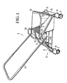
- the cleaning trolley 1 shown in FIG. 1 has a base frame 2, which is essentially formed from two side brackets 3, 4 and two cross struts 5, 6, which connect the ends of the side brackets 3, 4, which are located opposite one another. Swivel castors 7, which are provided with bumpers 8, are inserted into the lower openings of the side brackets 3, 4.
- the cross struts 5, 6 are connected to one another via a plurality of longitudinal struts 9.
- a bridge-shaped central strut 10 for connecting the two side brackets 3, 4 is arranged.
- the central strut 10 is clamped to the side brackets 3, 4 by means of wedge-shaped clamping elements 11.
- a bucket 12 On the floor grid formed by the longitudinal struts 9 there is a bucket 12 which engages with its edge 13 in a recess 14 of the central strut 10 (not visible in FIG. 1).
- a press stand 16 is inserted on the central strut 10 in a plug-in opening 15 (likewise not visible).
- a U-shaped handle bar 17 is attached to the central strut 10, which engages with guide pins 18 and 19 in bores 20 and grooves 21 on the central strut 10 and on the tensioning elements 11.
- the side brackets 3, 4 each have two perpendicular outer portions 22, to which the cross struts 5, 6 and the castors 7 are attached with the bumpers 8.
- a central section 23 which extends approximately horizontally and to which the central strut 10 is attached.
- the bucket 12 stands on the longitudinal struts 9 and rests on one side against the central strut 10 and on the other side against the respective cross strut 5, which for this purpose slightly protrude beyond the longitudinal struts 9.
- the handling bracket 17 can be pivoted by approximately 90 ° about its axis of rotation located below in the center of the central strut 10 and is guided with guide pins 19 in the grooves 21 provided on the tensioning elements 11.
- the central strut 10 is provided at the level of the projecting edge 13 of the bucket 12 with recesses 14 into which the edge 13 of the bucket 12 engages.
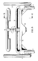
- the recess 14 can be seen in full length in FIG. 4.
- a bulge 24 is provided on the underside of the central strut 10, into which the insertion opening 15 for the press stand 16 extends.
- the configuration of the central strut 10 is shown even more clearly in FIG. 5.
- the tensioning elements 11 are inserted above the side brackets 3, 4 in the longitudinal direction in a form-fitting manner in the central strut 10.
- the press stand 16 is rotatably mounted in the insertion opening 15 and can be pulled vertically upwards out of the insertion opening 15.
- FIG. 6 shows how the projecting edge 13 of the bucket 12 can be inserted into the recess 14 of the central strut 10 from the side.
- the top of the central strut 10 has bevels 25 sloping towards the buckets 12, the front and rear edges 26, 27 of the central strut 10 each projecting beyond the interior of the buckets 12.
- cylindrical guide bushes 28 with bores 20 are provided for the articulation of the handle bar 17.
- Fig. 7 the attachment of the handle bar 17 to the central strut 10 is shown.
- the lower guide pins 18 of the handling bracket 17 are rotatably mounted in the bores 20 of the center strut 10, while the upper guide pins 19 of the handling bracket 17 are guided in the grooves 21 of the clamping elements 11 which are formed in the shape of a segment of a circle.
- the bores 20 for receiving the lower guide pins 18 of the handling bracket 17 are provided in guide bushes 28 inserted into the central strut 10.
- the longitudinal struts 9 are first inserted into the cross struts 5, 6 in order to form a grate.
- the side brackets 3, 4 are then fastened to the central strut 10 with the aid of the tensioning elements 11.
- the side brackets 3, 4 are passed with their vertical outer sections 22 through the likewise perpendicular bores in the cross struts 5, 6 and provided with the bumpers 8 and the steering rollers 7.
- the handle bar 17 is attached to the central strut 10 by slightly spreading its two side legs apart, by inserting the guide pins 18 into the bores 20 and the guide pins 19 into the grooves 21.
- the press stand 16 is inserted vertically from above into the insertion opening 15 of the central strut 10, so that it can be rotated about its vertical axis.
Landscapes
- Engineering & Computer Science (AREA)
- Chemical & Material Sciences (AREA)
- Combustion & Propulsion (AREA)
- Transportation (AREA)
- Mechanical Engineering (AREA)
- Handcart (AREA)
- Supporting Of Heads In Record-Carrier Devices (AREA)
- Automatic Analysis And Handling Materials Therefor (AREA)
- Vehicle Body Suspensions (AREA)
Priority Applications (1)
| Application Number | Priority Date | Filing Date | Title |
|---|---|---|---|
| AT91103798T ATE91866T1 (de) | 1990-04-14 | 1991-03-13 | Reinigungswagen. |
Applications Claiming Priority (2)
| Application Number | Priority Date | Filing Date | Title |
|---|---|---|---|
| DE9004319U | 1990-04-14 | ||
| DE9004319U DE9004319U1 (de) | 1990-04-14 | 1990-04-14 | Reinigungswagen |
Publications (2)
| Publication Number | Publication Date |
|---|---|
| EP0452674A1 true EP0452674A1 (fr) | 1991-10-23 |
| EP0452674B1 EP0452674B1 (fr) | 1993-07-28 |
Family
ID=6852918
Family Applications (1)
| Application Number | Title | Priority Date | Filing Date |
|---|---|---|---|
| EP91103798A Expired - Lifetime EP0452674B1 (fr) | 1990-04-14 | 1991-03-13 | Chariot de nettoyage |
Country Status (3)
| Country | Link |
|---|---|
| EP (1) | EP0452674B1 (fr) |
| AT (1) | ATE91866T1 (fr) |
| DE (2) | DE9004319U1 (fr) |
Cited By (5)
| Publication number | Priority date | Publication date | Assignee | Title |
|---|---|---|---|---|
| GB2388577A (en) * | 2002-04-25 | 2003-11-19 | Numatic Int Ltd | Janitorial trolley |
| USD624271S1 (en) | 2009-11-03 | 2010-09-21 | Ecolab Inc. | Cleaning trolley |
| USD624269S1 (en) | 2009-11-03 | 2010-09-21 | Ecolab Inc. | Cleaning trolley |
| USD624270S1 (en) | 2009-11-03 | 2010-09-21 | Ecolab Inc. | Cleaning trolley |
| USD624724S1 (en) | 2009-11-03 | 2010-09-28 | Ecolab Inc. | Cleaning trolley |
Families Citing this family (4)
| Publication number | Priority date | Publication date | Assignee | Title |
|---|---|---|---|---|
| DE9206733U1 (de) * | 1992-05-19 | 1992-07-30 | Vermop Salmon GmbH, 6980 Wertheim | Reinigungswagen |
| DE29808326U1 (de) | 1998-05-12 | 1998-09-17 | Breest, Ernst-Jürgen, 90547 Stein | Reinigungswagen, insbesondere Naßwischwagen |
| US9980623B2 (en) | 2008-11-05 | 2018-05-29 | Ecolab Usa Inc. | Cleaning trolley |
| DE102013011631A1 (de) * | 2013-07-12 | 2015-01-15 | Carl Freudenberg Kg | Reinigungswagen |
Citations (3)
| Publication number | Priority date | Publication date | Assignee | Title |
|---|---|---|---|---|
| DE2741836A1 (de) * | 1977-09-16 | 1979-03-29 | Floordress Reinigungsgeraete | Reinigungswagen |
| DE3037442A1 (de) * | 1980-10-03 | 1982-05-13 | Rheinwerk Meisenburg & Ahleff GmbH, 4000 Düsseldorf | Fahrbarer waeschesackstaender |
| DE8509181U1 (de) * | 1985-03-27 | 1985-05-09 | NWG Nord-West-Gebäudereinigung GmbH & Co KG, 4100 Duisburg | Gerätewagen für Reinigungszwecke |
-
1990
- 1990-04-14 DE DE9004319U patent/DE9004319U1/de not_active Expired - Lifetime
-
1991
- 1991-03-13 AT AT91103798T patent/ATE91866T1/de not_active IP Right Cessation
- 1991-03-13 EP EP91103798A patent/EP0452674B1/fr not_active Expired - Lifetime
- 1991-03-13 DE DE9191103798T patent/DE59100218D1/de not_active Expired - Fee Related
Patent Citations (3)
| Publication number | Priority date | Publication date | Assignee | Title |
|---|---|---|---|---|
| DE2741836A1 (de) * | 1977-09-16 | 1979-03-29 | Floordress Reinigungsgeraete | Reinigungswagen |
| DE3037442A1 (de) * | 1980-10-03 | 1982-05-13 | Rheinwerk Meisenburg & Ahleff GmbH, 4000 Düsseldorf | Fahrbarer waeschesackstaender |
| DE8509181U1 (de) * | 1985-03-27 | 1985-05-09 | NWG Nord-West-Gebäudereinigung GmbH & Co KG, 4100 Duisburg | Gerätewagen für Reinigungszwecke |
Cited By (6)
| Publication number | Priority date | Publication date | Assignee | Title |
|---|---|---|---|---|
| GB2388577A (en) * | 2002-04-25 | 2003-11-19 | Numatic Int Ltd | Janitorial trolley |
| GB2388577B (en) * | 2002-04-25 | 2004-08-11 | Numatic Int Ltd | Improvements in and relating to janitorial trolleys |
| USD624271S1 (en) | 2009-11-03 | 2010-09-21 | Ecolab Inc. | Cleaning trolley |
| USD624269S1 (en) | 2009-11-03 | 2010-09-21 | Ecolab Inc. | Cleaning trolley |
| USD624270S1 (en) | 2009-11-03 | 2010-09-21 | Ecolab Inc. | Cleaning trolley |
| USD624724S1 (en) | 2009-11-03 | 2010-09-28 | Ecolab Inc. | Cleaning trolley |
Also Published As
| Publication number | Publication date |
|---|---|
| DE9004319U1 (de) | 1990-06-28 |
| EP0452674B1 (fr) | 1993-07-28 |
| ATE91866T1 (de) | 1993-08-15 |
| DE59100218D1 (de) | 1993-09-02 |
Similar Documents
| Publication | Publication Date | Title |
|---|---|---|
| DE1116354B (de) | Zusammenklappbarer Bettrahmen | |
| DE2449555A1 (de) | Transportwagen | |
| DE2624478C2 (de) | Griffbefestigung an einem Geschirr | |
| EP0452674B1 (fr) | Chariot de nettoyage | |
| EP0570900A1 (fr) | Charriot de nettoyage | |
| DE2419546B2 (de) | Schrank mit herausziehbaren schubladenelementen | |
| EP0457034A1 (fr) | Séchoir à linge pliant | |
| DE2023011C3 (fr) | ||
| DE3021098C2 (fr) | ||
| DE8614831U1 (de) | Einkaufswagen | |
| DE1997275U (de) | Hublader. | |
| DE19860213B4 (de) | Hordenwagen | |
| DE354373C (de) | Geraet zur Befoerderung von Koffern | |
| DE2709018C2 (de) | Zweirädriger Transportkarren | |
| DE1757150C2 (de) | Flaschenkorb für Förderketten-Flaschenreinigungsmaschinen | |
| DE2055798A1 (de) | Handkehrmaschine | |
| DE2741836C2 (de) | Reinigungswagen | |
| DE2815415A1 (de) | Transportroller, insbesondere einkaufsroller | |
| DE2747153C2 (de) | Schwimmrahmen und/oder Bremsträger von Scheibenbremsen | |
| DE2903781B2 (de) | Klapptritt | |
| DE3008507C2 (fr) | ||
| DE3703274A1 (de) | Vorrichtung zum trocknen und ablegen von waesche | |
| DE102005020057B3 (de) | Transportkarrenstruktur | |
| DE1429746C (de) | Aufhängevorrichtung, insbesondere für Handtücher od.dgl | |
| DE9402552U1 (de) | Reinigungswagen |
Legal Events
| Date | Code | Title | Description |
|---|---|---|---|
| PUAI | Public reference made under article 153(3) epc to a published international application that has entered the european phase |
Free format text: ORIGINAL CODE: 0009012 |
|
| AK | Designated contracting states |
Kind code of ref document: A1 Designated state(s): AT BE CH DE DK ES FR GB GR IT LI LU NL SE |
|
| 17P | Request for examination filed |
Effective date: 19920123 |
|
| 17Q | First examination report despatched |
Effective date: 19930113 |
|
| GRAA | (expected) grant |
Free format text: ORIGINAL CODE: 0009210 |
|
| AK | Designated contracting states |
Kind code of ref document: B1 Designated state(s): AT BE CH DE DK ES FR GB GR IT LI LU NL SE |
|
| PG25 | Lapsed in a contracting state [announced via postgrant information from national office to epo] |
Ref country code: IT Free format text: LAPSE BECAUSE OF FAILURE TO SUBMIT A TRANSLATION OF THE DESCRIPTION OR TO PAY THE FEE WITHIN THE PRE;WARNING: LAPSES OF ITALIAN PATENTS WITH EFFECTIVE DATE BEFORE 2007 MAY HAVE OCCURRED AT ANY TIME BEFORE 2007. THE CORRECT EFFECTIVE DATE MAY BE DIFFERENT FROM THE ONE RECORDED.SCRIBED TIME-LIMIT Effective date: 19930728 Ref country code: ES Free format text: THE PATENT HAS BEEN ANNULLED BY A DECISION OF A NATIONAL AUTHORITY Effective date: 19930728 Ref country code: NL Effective date: 19930728 Ref country code: GB Effective date: 19930728 Ref country code: SE Effective date: 19930728 Ref country code: FR Effective date: 19930728 Ref country code: GR Free format text: LAPSE BECAUSE OF FAILURE TO SUBMIT A TRANSLATION OF THE DESCRIPTION OR TO PAY THE FEE WITHIN THE PRESCRIBED TIME-LIMIT Effective date: 19930728 Ref country code: DK Effective date: 19930728 |
|
| REF | Corresponds to: |
Ref document number: 91866 Country of ref document: AT Date of ref document: 19930815 Kind code of ref document: T |
|
| REF | Corresponds to: |
Ref document number: 59100218 Country of ref document: DE Date of ref document: 19930902 |
|
| EN | Fr: translation not filed | ||
| NLV1 | Nl: lapsed or annulled due to failure to fulfill the requirements of art. 29p and 29m of the patents act | ||
| GBV | Gb: ep patent (uk) treated as always having been void in accordance with gb section 77(7)/1977 [no translation filed] |
Effective date: 19930728 |
|
| PG25 | Lapsed in a contracting state [announced via postgrant information from national office to epo] |
Ref country code: AT Effective date: 19940313 |
|
| PG25 | Lapsed in a contracting state [announced via postgrant information from national office to epo] |
Ref country code: CH Effective date: 19940331 Ref country code: LI Effective date: 19940331 Ref country code: LU Free format text: LAPSE BECAUSE OF NON-PAYMENT OF DUE FEES Effective date: 19940331 Ref country code: BE Effective date: 19940331 |
|
| PLBE | No opposition filed within time limit |
Free format text: ORIGINAL CODE: 0009261 |
|
| STAA | Information on the status of an ep patent application or granted ep patent |
Free format text: STATUS: NO OPPOSITION FILED WITHIN TIME LIMIT |
|
| 26N | No opposition filed | ||
| REG | Reference to a national code |
Ref country code: CH Ref legal event code: PL |
|
| PG25 | Lapsed in a contracting state [announced via postgrant information from national office to epo] |
Ref country code: DE Effective date: 19941201 |
|
| BERE | Be: lapsed |
Owner name: VERMOP SALMON G.M.B.H. Effective date: 19941031 |