EP0452687A1 - Procédé pour l'alimentation de pots de ruban aux machines textiles, et dispositif pour la mise en oeuvre de ce procédé - Google Patents
Procédé pour l'alimentation de pots de ruban aux machines textiles, et dispositif pour la mise en oeuvre de ce procédé Download PDFInfo
- Publication number
- EP0452687A1 EP0452687A1 EP91104297A EP91104297A EP0452687A1 EP 0452687 A1 EP0452687 A1 EP 0452687A1 EP 91104297 A EP91104297 A EP 91104297A EP 91104297 A EP91104297 A EP 91104297A EP 0452687 A1 EP0452687 A1 EP 0452687A1
- Authority
- EP
- European Patent Office
- Prior art keywords
- sliver
- cans
- machines
- movable means
- spinning
- Prior art date
- Legal status (The legal status is an assumption and is not a legal conclusion. Google has not performed a legal analysis and makes no representation as to the accuracy of the status listed.)
- Withdrawn
Links
- 239000004753 textile Substances 0.000 title claims abstract description 21
- 238000000034 method Methods 0.000 title claims abstract description 17
- 238000009987 spinning Methods 0.000 claims abstract description 45
- 238000007383 open-end spinning Methods 0.000 claims abstract description 10
- 230000007935 neutral effect Effects 0.000 claims abstract description 9
- 238000004519 manufacturing process Methods 0.000 claims abstract description 7
- 230000000712 assembly Effects 0.000 description 2
- 238000000429 assembly Methods 0.000 description 2
- 238000003860 storage Methods 0.000 description 2
- 230000001419 dependent effect Effects 0.000 description 1
- 238000010586 diagram Methods 0.000 description 1
Images


Classifications
-
- D—TEXTILES; PAPER
- D01—NATURAL OR MAN-MADE THREADS OR FIBRES; SPINNING
- D01H—SPINNING OR TWISTING
- D01H9/00—Arrangements for replacing or removing bobbins, cores, receptacles, or completed packages at paying-out or take-up stations ; Combination of spinning-winding machine
- D01H9/005—Arrangements for replacing or removing bobbins, cores, receptacles, or completed packages at paying-out or take-up stations ; Combination of spinning-winding machine for removing empty packages or cans and replacing by completed (full) packages or cans at paying-out stations; also combined with piecing of the roving
- D01H9/008—Arrangements for replacing or removing bobbins, cores, receptacles, or completed packages at paying-out or take-up stations ; Combination of spinning-winding machine for removing empty packages or cans and replacing by completed (full) packages or cans at paying-out stations; also combined with piecing of the roving for cans
Definitions
- This invention concerns a method and an apparatus suitable to feed cans to textile machines.
- the invention provides for the automatic feed of cans full of textile sliver to, and the automatic removal of empty cans from, textile machines and, in particular, spinning machines of the open-end type.
- the invention concerns in particular, but not only, cans of an elongate type, namely cans having one dimension of their horizontal section greater than the other, such as the rectangular cams to which we shall refer as an example in the description which follows.
- These textile machines may all be those which process slivers held in cams, such as fly frames, spinning machines and, in particular, the open-end spinning machines to which we shall refer as an example in the following description.
- the trolleys work at one machine side at a time along set paths and handle the normal round cans. Examples of these solutions are disclosed in WO-A-06358, FR-A-2.367,843, DE-A-3.440.598 and DE-A-3.505.494.
- the present applicant has the purpose of providing a method and relative apparatus suitable to handle full cans and empty cans, preferably of an elongate type, by placing them directly to feed a spinning machine or other textile machine or by removing them from their feed positions.
- the invention arranges that one or more movable trolleys, the number of which depends on the spinning machines of which the plant consists, cooperate directly with sliver production machines such as drawing frames, for instance.
- Each drawing frame fills with sliver elongate cans which, when filled, are loaded automatically onto movable trolleys for delivery to the spinning zone.
- the trolley After a full elongate can has been loaded, the trolley is sent on a path through the spinning machines.
- the trolley can move automatically along pre-set paths and can be, for instance, of a type guided by a magnetic guide wire; it passes in one single direction between pairs of adjacent spinning machines. As it is equipped with means to communicate with spinning units requiring a change of feed, it turns the full can, in correspondence with those units, towards the side of the machine to which those units belong.
- the trolley of the invention during its passage can feed equally well either of the the contiguous spinning machines and can turn the full can towards either of those spinning machines.
- the can is unloaded from the trolley and positioned directly in correspondence with the spinning unit for which the can has been requested.
- the trolley is also provided with suitable means to withdraw and to load on the trolley the empty can to be removed, and the empty can is unloaded automatically thereafter at the drawing frames or at any desired collection station.
- the trolley can also be equipped advantageously with means to engage the pre-positioned end of the sliver on the full can.
- the end of the sliver can be brought to cooperate directly with the spinning unit in the automatic restarting of the relative spinning process.
- the invention provides a working method and apparatus which are well adapted to present spinning requirements, particularly as regards open-end spinning machines fed from rectangular cans or cans of any other elongate shape.
- the invention can be applied also to other cases relating to various machines that process sliver, for instance in the handling of cans between the drawing frames and the fly frames, and intermediate stations may also be included for the storage of full and empty cans.
- Fig.1 shows a possible lay-out of a spinning shop containing open-end spinning machines 10 and drawing frames 11.
- Elongate cans 12 are filled with sliver in the drawing frames 11 and are removed therefrom on movable trolleys 13 which provide a secure connection between the open-end spinning machines 10 and drawing frames 11.
- a full can, bearing the reference 112, is loaded on the trolley 13 in a neutral or waiting position, as will be described better hereinafter.
- the trolley 13 follows a path 14 connecting the drawing frame 11 to a main path 15 according to the arrow 16 and runs along a part or the whole of the first side of the first open-end spinning machine 10.
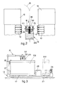
- the full can 112 is positioned on the trolley 13 on top of a rotary platform 17, which can be actuated to rotate by 90° clockwise or anticlockwise according to the arrows 18 (see Figs.2 and 3).
- the position called "neutral" of the full can 112 on the platform 17 is such that the can 112 is located at a right angle to the analogous cans 12 taking part in the processing on the spinning machines 10 while the trolley 13 is moving on the main paths 15.
- the full can 112 is therefore ready, whether it is travelling on the segment of path outside the first spinning machine 10 or on the segment of path between the spinning machines 10 (see Fig.2), to be rotated in one direction or the other (position shown with lines of dashes in Fig. 2) according to the arrows 18 so as to meet the requirements for feed of a full can 112.
- the movable trolley 13 is equipped with at least one space to hold an empty can 212 taken from the spinning machines 10; this empty can 212 is advantageously positioned perpendicularly to the full can 112 when the latter is in its neutral position.
- a trolley 13 is travelling towards the zone of the drawing frames 11 and is carrying the only empty can 212 to be removed.
- the trolley 13 can run advantageously along direct return paths 19, which can be used equally well for its outward journey if it has to reach the farthest spinning machines 10 directly.
- the trolley 13 is equipped preferably with means suitable to engage the end of the sliver 20 pre-positioned on the full can 112.
- Such means may be a pair of rotary and possibly telescopic arms 21 which bear a terminal gripper assembly 22.
- Each rotary arm 21 is located at a lateral position on the trolley 13 so that it can descend vertically according to the arrow 23 to grip the end 20 of the sliver whether the full can 112 has been rotated to the right or the left.
- the arm 21 is rotated according to the arrows 24 and is possibly extended to take the end 20 of the sliver directly to a spinning unit which is to be restarted or to an automatic carriage which restarts the spinning and which is positioned, as is known, on the spinning machine 10.
- Each arm 21 may bear, equally well, terminal assemblies 25 to discharge a full can 112 from the trolley 13. These discharge assemblies 25 descend vertically according to the arrow 23 to cooperate with the inner upper edge of the full can 112 and discharge the full can 112 thereafter from the trolley 13 by means of rotation of the arm 21 according to the arrows 24.
- one rotary arm alone 21 is provided and is located in a central position, advantageously on the rotary platform 17, and carries out discharge of the full can 112 either to the right or the left of the trolley 13.
- the trolley 13 is also equipped with an assembly 26 to engage and handle empty cans 212; this assembly 26 may be able to slide and extend and may be equipped advantageously with magnetic means capable of being coupled to analogous magnetic means 27 included on the cans 12.
- Fig.3 shows an assembly 28 which actuates and controls the functions cited above of the trolley 13.
- Figs.4a and 4b respectively show as an example a lengthwise section and a plan view of a known type of elongate can 12 which can be used with this invention.
- the can 12 has a rectangular section and a movable bottom 29, which cooperates with springs 30 and with a pantograph-type balancing system 31.
Landscapes
- Engineering & Computer Science (AREA)
- Mechanical Engineering (AREA)
- Textile Engineering (AREA)
- Spinning Or Twisting Of Yarns (AREA)
- Preliminary Treatment Of Fibers (AREA)
Applications Claiming Priority (2)
| Application Number | Priority Date | Filing Date | Title |
|---|---|---|---|
| IT8336290 | 1990-04-10 | ||
| IT83362A IT1239669B (it) | 1990-04-10 | 1990-04-10 | Procedimento di alimentazione automatica di vasi di nastro in macchine tessili e apparecchiatura adottante tale procedimento |
Publications (1)
| Publication Number | Publication Date |
|---|---|
| EP0452687A1 true EP0452687A1 (fr) | 1991-10-23 |
Family
ID=11320751
Family Applications (1)
| Application Number | Title | Priority Date | Filing Date |
|---|---|---|---|
| EP91104297A Withdrawn EP0452687A1 (fr) | 1990-04-10 | 1991-03-20 | Procédé pour l'alimentation de pots de ruban aux machines textiles, et dispositif pour la mise en oeuvre de ce procédé |
Country Status (2)
| Country | Link |
|---|---|
| EP (1) | EP0452687A1 (fr) |
| IT (1) | IT1239669B (fr) |
Cited By (6)
| Publication number | Priority date | Publication date | Assignee | Title |
|---|---|---|---|---|
| US5297317A (en) * | 1990-05-14 | 1994-03-29 | Trutzschler Gmbh & Co. Kg | Coiler can conveyor with positive guidance between machine rows |
| DE19526891A1 (de) * | 1995-07-22 | 1997-01-23 | Schlafhorst & Co W | Kannenwechseleinrichtung für Rechteckkannen mit Dreheinrichtung |
| EP0825283A3 (fr) * | 1996-08-16 | 1999-01-27 | Manfred Langen | Méthode pour remplacer des pots de filature à un métier à filer |
| FR2813069A1 (fr) * | 2000-08-16 | 2002-02-22 | Truetzschler & Co | Dispositif de fond mobile sur un pot de filature pour ruban de fibres textiles |
| CN107002311A (zh) * | 2014-12-16 | 2017-08-01 | 里特机械公司 | 纺纱机 |
| WO2018024588A1 (fr) * | 2016-08-02 | 2018-02-08 | Koenig Reinhard | Dispositif de transport de récipients de stockage d'une bande de fibres ainsi que dispositif de production de fils |
Citations (6)
| Publication number | Priority date | Publication date | Assignee | Title |
|---|---|---|---|---|
| FR2367843A1 (fr) * | 1976-10-14 | 1978-05-12 | Schlafhorst & Co W | Procede et appareil pour le remplacement des pots de ruban de fibres pour metier a filer |
| DE3440598A1 (de) * | 1984-11-07 | 1986-05-15 | Fritz 7347 Bad Überkingen Stahlecker | Spinnmaschine mit einer vielzahl nebeneinander angeordneter spinnstellen |
| GB2171121A (en) * | 1985-02-16 | 1986-08-20 | Reiners Verwaltungs Gmbh | Replacing empty cans by cans filled with fibre lap in a textile machine |
| DE3505494A1 (de) * | 1985-02-16 | 1986-09-04 | Langen, Manfred, 4050 Mönchengladbach | Verfahren und vorrichtung zum austauschen leerer kannen gegen gefuellte kannen |
| WO1986006358A1 (fr) * | 1985-04-30 | 1986-11-06 | Büro Patent Ag | Installation et procede d'amenee automatique de pots remplis et d'evacuation automatique de pots vides dans un metier a filer |
| EP0340459A1 (fr) * | 1988-05-02 | 1989-11-08 | SCAGLIA S.p.A. | Dispositif pour distribuer automatiquement des mèches aux métiers à filer |
-
1990
- 1990-04-10 IT IT83362A patent/IT1239669B/it active IP Right Grant
-
1991
- 1991-03-20 EP EP91104297A patent/EP0452687A1/fr not_active Withdrawn
Patent Citations (6)
| Publication number | Priority date | Publication date | Assignee | Title |
|---|---|---|---|---|
| FR2367843A1 (fr) * | 1976-10-14 | 1978-05-12 | Schlafhorst & Co W | Procede et appareil pour le remplacement des pots de ruban de fibres pour metier a filer |
| DE3440598A1 (de) * | 1984-11-07 | 1986-05-15 | Fritz 7347 Bad Überkingen Stahlecker | Spinnmaschine mit einer vielzahl nebeneinander angeordneter spinnstellen |
| GB2171121A (en) * | 1985-02-16 | 1986-08-20 | Reiners Verwaltungs Gmbh | Replacing empty cans by cans filled with fibre lap in a textile machine |
| DE3505494A1 (de) * | 1985-02-16 | 1986-09-04 | Langen, Manfred, 4050 Mönchengladbach | Verfahren und vorrichtung zum austauschen leerer kannen gegen gefuellte kannen |
| WO1986006358A1 (fr) * | 1985-04-30 | 1986-11-06 | Büro Patent Ag | Installation et procede d'amenee automatique de pots remplis et d'evacuation automatique de pots vides dans un metier a filer |
| EP0340459A1 (fr) * | 1988-05-02 | 1989-11-08 | SCAGLIA S.p.A. | Dispositif pour distribuer automatiquement des mèches aux métiers à filer |
Cited By (7)
| Publication number | Priority date | Publication date | Assignee | Title |
|---|---|---|---|---|
| US5297317A (en) * | 1990-05-14 | 1994-03-29 | Trutzschler Gmbh & Co. Kg | Coiler can conveyor with positive guidance between machine rows |
| GB2244290B (en) * | 1990-05-14 | 1994-08-03 | Truetzschler Gmbh & Co Kg | Apparatus for transporting at least one can between a sliver-supplying textile machine, and a sliver-fed textile machine |
| DE19526891A1 (de) * | 1995-07-22 | 1997-01-23 | Schlafhorst & Co W | Kannenwechseleinrichtung für Rechteckkannen mit Dreheinrichtung |
| EP0825283A3 (fr) * | 1996-08-16 | 1999-01-27 | Manfred Langen | Méthode pour remplacer des pots de filature à un métier à filer |
| FR2813069A1 (fr) * | 2000-08-16 | 2002-02-22 | Truetzschler & Co | Dispositif de fond mobile sur un pot de filature pour ruban de fibres textiles |
| CN107002311A (zh) * | 2014-12-16 | 2017-08-01 | 里特机械公司 | 纺纱机 |
| WO2018024588A1 (fr) * | 2016-08-02 | 2018-02-08 | Koenig Reinhard | Dispositif de transport de récipients de stockage d'une bande de fibres ainsi que dispositif de production de fils |
Also Published As
| Publication number | Publication date |
|---|---|
| IT9083362A1 (it) | 1991-10-10 |
| IT9083362A0 (it) | 1990-04-10 |
| IT1239669B (it) | 1993-11-11 |
Similar Documents
| Publication | Publication Date | Title |
|---|---|---|
| EP0340459B1 (fr) | Dispositif pour distribuer automatiquement des mèches aux métiers à filer | |
| JPH0436995B2 (fr) | ||
| US4955782A (en) | Device to palletize yarn packages | |
| US4565278A (en) | Method of transferring yarn packages | |
| US4583358A (en) | Roving-bobbin feeder for spinning machine | |
| JPS63202566A (ja) | 多数の位置を有する紡糸機又は撚糸機へ、或いは該機械からのパッケージの運搬装置 | |
| US5081744A (en) | Method and device for changing fiber sliver containers on textile machines | |
| EP0452687A1 (fr) | Procédé pour l'alimentation de pots de ruban aux machines textiles, et dispositif pour la mise en oeuvre de ce procédé | |
| EP0311394A1 (fr) | Système pour manipuler des bobines | |
| US5495991A (en) | Apparatus for transporting empty yarn winding tubes and fully wound textile yarn packages to and from a winding location | |
| US4690342A (en) | Textile machine for producing cross-wound bobbins | |
| EP0276569B1 (fr) | Procédé et dispositif de transport d'articles | |
| US4739611A (en) | Process and apparatus for replacement of an empty with a full roving bobbin in a spinning machine, particularly a ring spinning machine | |
| US5628173A (en) | Method and apparatus for feeding sliver to a spinning machine without sliver cans at spinning stations | |
| EP0310567B1 (fr) | Dispositif dans un banc à broches pour remplacer automatiquement des bobines de mèche contre des tubes de bobine pour l'enroulement de la mèche | |
| EP0339273B1 (fr) | Procédé pour transporter des bobines de mêche, la mêche étant prépositionnée | |
| CN213169978U (zh) | 一种纱筒提取器 | |
| US5337967A (en) | Textile yarn processing apparatus | |
| US3370412A (en) | Apparatus for use in connection with two-for-one twisting machines for automatically changing bobbin units | |
| US6012671A (en) | Tube feeding device for cheese-producing textile machines | |
| JPH0518925B2 (fr) | ||
| JPH04222238A (ja) | リング精紡機のクリール内において精紡作業が終わった粗糸ボビンを新しい粗糸ボビンと自動的に交換するための装置 | |
| US5193333A (en) | Integrated system for drawing and spinning operations | |
| US5575142A (en) | Method of automatically servicing winding apparatus in multi-station textile machines | |
| US4682466A (en) | Device to doff yarn packages on ring spinning machines |
Legal Events
| Date | Code | Title | Description |
|---|---|---|---|
| PUAI | Public reference made under article 153(3) epc to a published international application that has entered the european phase |
Free format text: ORIGINAL CODE: 0009012 |
|
| AK | Designated contracting states |
Kind code of ref document: A1 Designated state(s): AT BE CH DE ES FR GB LI |
|
| 17P | Request for examination filed |
Effective date: 19920406 |
|
| 17Q | First examination report despatched |
Effective date: 19930908 |
|
| STAA | Information on the status of an ep patent application or granted ep patent |
Free format text: STATUS: THE APPLICATION IS DEEMED TO BE WITHDRAWN |
|
| 18D | Application deemed to be withdrawn |
Effective date: 19940119 |