EP0452738A1 - Dispositif auxiliaire pour un métier à tisser - Google Patents
Dispositif auxiliaire pour un métier à tisser Download PDFInfo
- Publication number
- EP0452738A1 EP0452738A1 EP91105319A EP91105319A EP0452738A1 EP 0452738 A1 EP0452738 A1 EP 0452738A1 EP 91105319 A EP91105319 A EP 91105319A EP 91105319 A EP91105319 A EP 91105319A EP 0452738 A1 EP0452738 A1 EP 0452738A1
- Authority
- EP
- European Patent Office
- Prior art keywords
- shaft
- operatively connected
- additional device
- shafts
- leno
- Prior art date
- Legal status (The legal status is an assumption and is not a legal conclusion. Google has not performed a legal analysis and makes no representation as to the accuracy of the status listed.)
- Withdrawn
Links
- 239000004744 fabric Substances 0.000 claims abstract description 13
- 238000003780 insertion Methods 0.000 claims abstract description 5
- 230000037431 insertion Effects 0.000 claims abstract description 5
- 230000015572 biosynthetic process Effects 0.000 claims abstract description 3
- 238000009941 weaving Methods 0.000 claims description 17
- 238000004519 manufacturing process Methods 0.000 claims description 3
- 230000006641 stabilisation Effects 0.000 abstract 1
- 238000003860 storage Methods 0.000 description 4
- 238000010276 construction Methods 0.000 description 2
- 230000005540 biological transmission Effects 0.000 description 1
- 239000003086 colorant Substances 0.000 description 1
- 230000006835 compression Effects 0.000 description 1
- 238000007906 compression Methods 0.000 description 1
- 238000005520 cutting process Methods 0.000 description 1
- 230000001419 dependent effect Effects 0.000 description 1
- 238000000034 method Methods 0.000 description 1
- 230000000149 penetrating effect Effects 0.000 description 1
- 239000004753 textile Substances 0.000 description 1
Images

Classifications
-
- D—TEXTILES; PAPER
- D03—WEAVING
- D03C—SHEDDING MECHANISMS; PATTERN CARDS OR CHAINS; PUNCHING OF CARDS; DESIGNING PATTERNS
- D03C7/00—Leno or similar shedding mechanisms
-
- D—TEXTILES; PAPER
- D03—WEAVING
- D03C—SHEDDING MECHANISMS; PATTERN CARDS OR CHAINS; PUNCHING OF CARDS; DESIGNING PATTERNS
- D03C11/00—Selvedge shedding mechanisms not forming part of main shedding mechanism
Definitions
- the invention relates to an additional device for a weaving machine, in particular for a weaving machine with a correspondingly integrated lathe device for producing a weave, as well as with a treading device arranged inside or outside of the weaving machine and operatively connected to a first, driven shaft, of which several, in their Number of rods corresponding to the number of shafts, a lifting and / or lowering movement can be transferred to the associated shafts for shed formation with subsequent weft insertion.
- one or the other warp threads are essentially raised and lowered to form a so-called shed and a weft thread is inserted into the shed thus formed to produce textile fabrics by means of a corresponding shank control.
- the alternate lifting and lowering of different shafts and the respective weft insertion thus essentially create a weave, with the weft threads being cut off, for example, on the side.
- cutting the weft threads has the disadvantage that the selvedge formed in this way does not run evenly and therefore does not meet the requirements of certain types of fabric.
- weaving methods are also known in which the fabric is provided with a leno weave in order to achieve special properties.
- operable leno elements are provided in the weaving machine depending on the shaft movement, by means of which leno elements the respective warp threads in the fabric are crossed in such a way that the leno thread (warp thread), for example, once on the right and once on the left of the other warp thread (s) (standing threads) lies and this creates the usual leno binding.
- This leno movement is essentially coupled to the shaft movement and operatively connected (specialist conclusion), so that the lathe weave is dependent on the weave.
- a satin weave has a 4: 1 weave, in which four weft threads are inserted in the upper compartment and one weft thread in the lower compartment.
- the invention is therefore based on the object of providing an additional device for a weaving machine for the production of fabrics, in particular fabrics of the type mentioned, by means of which additional device shaft movements coordinated with the leno can be achieved and thus an exact closing of the leno threads can be achieved while at the same time the compartment for the satin weave of the mentioned types of fabric remains unchanged.
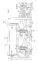
- FIG. 1 shows, in a schematically represented view, the construction system of a weaving machine designated as a whole by 100, and one can see shafts 90 mounted between two side parts 95, 95 'spaced apart from one another, with a correspondingly assigned turning device 300, 300'.
- the side parts 95.95 ' are connected to one another in a manner not shown by corresponding cross members 94.94'.
- the shafts 90 arranged one behind the other are moved up or down individually or in combination in order to achieve a so-called shedding in the direction of the arrow Z, Z '.
- the individual shaft 90' is operatively connected to a correspondingly assigned treading device 75 via a lever and linkage system designated as a whole by 80.
- the lever and linkage system 80 comprises a number of linkages 80 'which is identical to the number of shafts 90'.
- the treading device 75 is designed as a so-called kicking device.
- the treading device 75 shown schematically in FIG. 1 comprises a number of cam disks, not shown in more detail, arranged in a correspondingly designed housing 71, which are mounted on a shaft 73 arranged in the housing 71 and are operatively connected to it.
- a first toothed wheel 72 is mounted on the side of the housing 71 on the shaft 73 and is operatively connected to it.
- the first gear 72 stands over a link chain 76 or over a drive belt with a second Gear 77 in engagement, the second gear 77 mounted on a shaft 78 and operatively connected to this.
- the treading device 75 is actuated essentially by the shaft 78, which is driven by means not shown, and the parts 77, 76 and 73 which are operatively connected to it.
- the two shafts 73 and 78 are arranged parallel and offset in height from one another.
- the individual cam disks (not shown) which are arranged in the housing 71 and are mounted on the shaft 73 are each associated with a rocker arm, not shown, which is operatively connected thereto.
- a push rod 74 is articulated on each individual rocker arm. By means of the push rods 74, an approximately form-fitting transfer of energy is transmitted to the lever and linkage system 80 'operatively connected thereto for the lifting and / or lowering movement of the corresponding shafts 90' oriented in the direction of arrow Z, Z '.
- the lever and linkage system for the shafts 90 which is designated as a whole by 80, essentially comprises a number of push rods 81 arranged parallel to one another. On each push rod 81, two angular levers 84, 84 'arranged at a distance from one another are mounted.
- the angle levers 84, 84 ' which are pivotably mounted on the first push rod 81 in the direction of the arrow X''are each operatively connected to the correspondingly assigned shafts 90' via first and second lifting rods 87, 87 'and 86, 86'.
- the lifting rods 86, 86 'and 87, 87' are each arranged and guided in correspondingly designed housings 85, 85 'for the precise lifting and / or lowering movement of the shafts 90' in the direction of the arrows Z and Z '.
- a second push rod 82 is articulated to the one end of the first push rod 81 facing the treading device 75.
- the second push rod 82 is operatively connected at one end to a rocker arm 83, the rocker arm 83 also being operatively connected to the push rod 74 in the upper region and mounted on an axle body 83 '.
- the parts 83, 82, 81 and 84, 84 'and the parts 87, 87', 86, 86 ' together form the individual linkage, designated in its entirety with 80', which is associated with the individual shaft 90 'and with a corresponding one , not shown leno element is operatively connected.
- the treading device 75 is assigned an additional device, designated as a whole by 60, 160 or 260.
- the respective additional device 60, 160, 260 is operatively connected via a further toothed or chain wheel 65, 165, 265 and a link chain 66 or a drive belt to a further toothed or chain wheel 67 mounted on the first shaft 78.
- the toothed or sprocket 67 for the additional device 60, 160 or 260 is arranged on the shaft 78 at a distance from the toothed or sprocket 77 for the treading device 75.
- the two toothed or chain wheels 67, 77 are non-rotatably operatively connected to the driven shaft 78 by means of fastening means, not shown, for example by a tongue and groove connection known per se.
- the storage rack 10 has two side parts 11 and 11 'which are arranged at a distance from one another and provided with bores 12, 12' and a support plate 13 which connects the side parts 11, 11 'to one another, as shown in FIG Screws attached to the housing 71 of the treadmill 75.
- two bearing blocks 15, 15 ' are arranged and fixed at a distance from one another.
- the pillow blocks 15, 15 'each have a correspondingly designed bearing part 17, 17' and a support body 16, 16 'and a web 14, 14' arranged on the side thereof.
- a shaft 18 is arranged and supported at one end in the bearing part 17 and penetrates the bearing part 17 'at the other end.
- the gear or sprocket 65 which is operatively connected thereto and which is operatively connected to the driven first shaft 78 (FIG. 1) by means of the link chain 66 or the drive belt.
- the control device 30 which essentially comprises two eccentric elements 20 and 25 which are arranged at a small distance from one another on the shaft 18 and are not operatively connected to them in a manner shown.
- the first eccentric element 20 has a disk 23 and a plate 22 enclosing it in a positive and non-positive manner.
- a crank lever 21 is arranged or formed on the plate 22 on one side.
- the disk 23 is penetrated by an eccentrically arranged bore 23 ′ for the shaft 18.
- the second eccentric element 25 is designed analogously and comprises a plate 27 and a crank lever 26 arranged or molded thereon.
- the plate 27 likewise encloses a disc 28 (not visible in FIG.
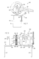
- FIG. 3 shows the additional device 60 seen from the other side and shown in perspective view and one can see the storage rack 10 with the two side parts 11, 11 ', the tensioning device 35 arranged thereon, the toothed or chain wheel 65 supported on the shaft 18 and the two eccentric elements 20 and 25 of the control device 30. Furthermore, the disks 23, 28 mounted eccentrically on the shaft 18 and the plates 22, 27 encompassing the disks 23, 28 with the crank levers 21 and 26 formed thereon and movable in the direction of the arrow X can be seen.
- the tensioning device 35 has a lever arm 32 which is supported on the side part 11 'with one end designed as a joint piece 32'. At the other end of the lever arm 32, a guide roller 33 for the link chain 66 (FIG. 2) is arranged.
- a guide piece 31 for a spring 31 '(compression spring) provided with a shoulder 31'' is also articulated on the lever arm 32.
- the pin-shaped guide piece 31 penetrates a support plate 34 fastened to the side part 11 'and provided with a correspondingly shaped opening (not shown).
- the spring 31' surrounds the guide piece 31 completely and is on the one hand on the shoulder 31 '' and on the other hand supported on the support plate 34.
- the lever arm 32 can be pivoted in the direction of the arrow B against the restoring force of the spring 31 'about the axis of the joint piece 32', which is not specified in any more detail.
- the tensioning device 35 essentially serves to ensure that the link chain 66, which connects the two sprockets or chain wheels 65, 67 to one another, or the correspondingly designed drive belt, with the lever arm 32, which can be pivoted in the direction of arrow B against the restoring force of the spring 31 ', or with the guide roller 33 with the toothed or sprockets in a manner not shown permanently in Intervention stands.
- the tensioning device 135 or 235 for one and the tensioning device, not shown, for the other embodiment variant of the additional device 60, 160 or 260 are designed essentially analogously.
- FIG. 4 shows the additional device 60 in plan view and one can see the bearing frame 10 with the carrier plate 13, the bearings 17, 17 'with the shaft 18 arranged thereon at a distance from one another, and the toothed or chain wheel 65 mounted laterally on the shaft 18
- the control device 30, which is essentially formed from the parts 20, 21, 22 and 25, 26, 27, is arranged between the two bearings 17, 17 '. Furthermore, the clamping device 35 with the lever arm 32 and the roller 33 arranged thereon can be seen.
- the two rods 80 ' are uncoupled from the treading device 75 and are operatively connected to the two crank levers 21, 26 of the additional device 60, and the two shafts 90' which are operatively connected to it in a manner not shown in greater detail with the one shown schematically in FIG shown turning device 300,300 'actuated in a time-coordinated manner.
- a 4: 1 weave is chosen for a satin weave.
- four threads are introduced into the upper compartment and one thread into the lower compartment, and a twist binding is carried out individually by means of the additional device 60 when the individual thread is introduced.
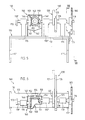
- the additional device 60 shows the second exemplary embodiment of the additional device 160 for the weaving machine 100 according to FIG. 1 in a schematically represented view and FIG. 6 in a corresponding top view.
- the additional device 160 comprises a bearing frame 110 essentially formed from side parts 111, 111 'and a carrier plate 113.
- Three bearing blocks 115, 115', 115 '' for a shaft 118, 118 'which are arranged at a distance from one another are arranged on the carrier plate 113 and fastened by means not shown.
- the gear or chain wheel 165 is arranged at one end of the shaft 118, a control device 130 is arranged between the two bearing blocks 115 ′ and 115 ′′, and a gear 150 is arranged between the two bearing blocks 115 ′′ and 115.
- the gear or chain wheel 165 is assigned the clamping device 135 shown schematically in FIG. 5, which, as already mentioned, is identical to the clamping device 35 described above in connection with FIG.
- a release element 170 is arranged at a distance from the bearing block 115 and is operatively connected to the shaft 118' in a manner not shown.
- the gearbox 150 arranged in a correspondingly designed gearbox 140 comprises a first bevel gear 151, a second bevel gear 152 and a third bevel gear 153.
- the gearbox 140 formed from two side walls 144, 144 ', a rear wall 145' and a front wall 145 (FIG. 6) closed on its upper side (FIG. 5) by a cover 143 which is articulated in a manner not shown in detail and on its lower side by a base 141 designed as an oil pan.
- An oil drain screw 142 is provided at the lowest point of the funnel-shaped bottom 141.
- the additional device 160 is shown in plan view, and you can see the gear or sprocket 165, the bearing frame 110 with the support plate 113, the control device 130 formed from the parts 120,121 and 125,126, the gear essentially formed by the bevel gears 151,152,153 150 and the gear box 140 formed approximately from the end and side walls 145, 145 'and 144, 144'.
- the bevel gear 151 is connected to the shaft 118 and to the bevel gear 152 which is mounted on an appropriately designed bearing block 154, and the bevel gear 152 is mounted on the shaft piece 118 ' Bevel gear 153 operatively connected.
- the shaft 118 mounted in the bearing blocks 115 ', 115'', the shaft piece 118' which is arranged offset to it and is operatively connected to the bevel gear 153 and is mounted in the bearing block 115 and on which the release element 170 is arranged and fastened.
- the additional device 160 is shown in a sectional view along the line VII-VII in FIG. 5, and the side part 111 'and the support plate 113 of the storage rack 110 and the clamping device 135 arranged thereon can also be seen. with the shaft 118 mounted thereon for the two eccentric disks 120, 125 with the crank levers 121, 126 respectively arranged thereon.
- the function of the additional device 160 described in connection with FIGS. 5, 6 and 7 is analogous to the previously described function of the additional device 60 according to FIGS. 2 to 4.
- a control element (not shown) for a selection, for example of yarns with different qualities or colors of the respective weft thread to be introduced, is controlled by the assigned gear 150 and the trigger element 170 correspondingly operatively connected thereto.
- FIG. 8 shows a schematically illustrated view of the third exemplary embodiment of the additional device 260 for the weaving machine 100 according to FIG. 1.
- the additional device 260 comprises an essentially formed from side parts 211, 211 'and a carrier plate 213 Bearing frame 210.
- Three bearing blocks 215, 215 ', 215''for a first shaft 218 and 218' are arranged at a distance from one another and fastened by means not shown.
- the toothed or chain wheel 265 with the correspondingly assigned clamping device 235 is arranged.
- a control device 230 formed from the parts 220 and 225 is arranged between the two bearing blocks 215 'and 215''.
- a gear 250 is arranged between the two bearing blocks 215 ′′ and 215, which comprises a first gear 251 that is operatively connected to the shaft 218, a second gear 252 that engages with it, and a third gear 253 and a fourth gear 254 that engages therewith .
- the two gear wheels 251, 254 arranged in parallel to one another are mounted on the shaft 218 or on the shaft 218 'arranged offset thereto, and the two gear wheels 252, 253 are mounted on a shaft 219 arranged in the bearing blocks 215, 215''.
- the control device 230 and the tensioning device 235 essentially correspond to the control device 30 and tensioning device 35 described in connection with FIGS. 2, 3 and 4.
- the function of the additional device 260 is analogous to the function of the additional device 60 and 160 described above.
- the only difference here from the additional device 160 is the design of the transmission 250.
Landscapes
- Engineering & Computer Science (AREA)
- Textile Engineering (AREA)
- Looms (AREA)
Applications Claiming Priority (2)
| Application Number | Priority Date | Filing Date | Title |
|---|---|---|---|
| CH1305/90 | 1990-04-18 | ||
| CH130590 | 1990-04-18 |
Publications (1)
| Publication Number | Publication Date |
|---|---|
| EP0452738A1 true EP0452738A1 (fr) | 1991-10-23 |
Family
ID=4207337
Family Applications (1)
| Application Number | Title | Priority Date | Filing Date |
|---|---|---|---|
| EP91105319A Withdrawn EP0452738A1 (fr) | 1990-04-18 | 1991-04-04 | Dispositif auxiliaire pour un métier à tisser |
Country Status (1)
| Country | Link |
|---|---|
| EP (1) | EP0452738A1 (fr) |
Cited By (1)
| Publication number | Priority date | Publication date | Assignee | Title |
|---|---|---|---|---|
| CN110424083A (zh) * | 2019-09-10 | 2019-11-08 | 常熟纺织机械厂有限公司 | 提花机的绞边装置 |
Citations (1)
| Publication number | Priority date | Publication date | Assignee | Title |
|---|---|---|---|---|
| FR2438104A1 (fr) * | 1978-10-03 | 1980-04-30 | Staubli Sa Ets | Perfectionnements aux ratieres pour metiers a tisser |
-
1991
- 1991-04-04 EP EP91105319A patent/EP0452738A1/fr not_active Withdrawn
Patent Citations (1)
| Publication number | Priority date | Publication date | Assignee | Title |
|---|---|---|---|---|
| FR2438104A1 (fr) * | 1978-10-03 | 1980-04-30 | Staubli Sa Ets | Perfectionnements aux ratieres pour metiers a tisser |
Cited By (2)
| Publication number | Priority date | Publication date | Assignee | Title |
|---|---|---|---|---|
| CN110424083A (zh) * | 2019-09-10 | 2019-11-08 | 常熟纺织机械厂有限公司 | 提花机的绞边装置 |
| CN110424083B (zh) * | 2019-09-10 | 2024-01-26 | 常熟纺织机械厂有限公司 | 提花机的绞边装置 |
Similar Documents
| Publication | Publication Date | Title |
|---|---|---|
| DE10128538B4 (de) | Webmaschine zum Herstellen eines Drehergewebes | |
| DE1710213A1 (de) | Verfahren und Vorrichtung fuer die Herstellung von Plueschgeweben | |
| DE19537277C1 (de) | Frottierwebmaschine mit einer Florhöhenverstelleinrichtung | |
| EP1008683B1 (fr) | Procédé pour compenser le changement de la longueur et de la tension de la chaíne et métier à tisser pour la mise en oeuvre du procédé | |
| DE2631142B2 (de) | Maschine zur Steuerung der Webschäfte einer Webmaschine | |
| EP1620588B2 (fr) | Procede pour faire fonctionner un metier a tisser | |
| CH644643A5 (de) | Webstuhl. | |
| EP0726342B1 (fr) | Métier à tisser à griffes avec des moyens de guidage | |
| EP0879308B1 (fr) | Dispositif de formation de lisiere pour metier mecanique | |
| EP0452738A1 (fr) | Dispositif auxiliaire pour un métier à tisser | |
| DE602004006729T2 (de) | Vorrichtung zum herstellen einer gewebekante an einem gewebe | |
| EP1108080B1 (fr) | Metier a tisser a lance comprenant au moins une bande a lance ainsi que des moyens de guidage | |
| DE69404252T2 (de) | Webladebewegung für eine Webmaschine | |
| CH601539A5 (en) | Wave shed loom leno selvedge | |
| CH541639A (de) | Getriebe einer Webmaschine für Dreherbindung | |
| DE19537867A1 (de) | Schußfadenschneidvorrichtung für Webmaschinen, insbesondere Doppelteppichwebmaschinen | |
| DE19856308B4 (de) | Verfahren zur Kompensation der Längungs- oder Spannungsänderung in einer Webkette und Webmaschine zur Durchführung des Verfahrens | |
| DE8116240U1 (de) | Vorrichtung zur fachbildung an webmaschinen | |
| DE1949300C (fr) | ||
| DE2844852C2 (de) | Greiferstangenantrieb für Webmaschinen | |
| DE3043147C2 (de) | Webmaschine mit Schneidvorrichtung | |
| DE69115874T2 (de) | Lageranordnung mit einem Spielabsorptionssystem | |
| DE7520574U (de) | Doppelplüsch-Webmaschine mit Entnahme der Schuß- und Polfäden von ortsfesten Spulen | |
| DE4123925C1 (en) | Installation for prodn. of fabric pattern - comprising drill device for receiving warp ends and consisting of rotationally symmetrical body having bores for receiving warp ends | |
| DE1953470A1 (de) | Einrichtung zum Verlagern der Grundkette bei Frottierwebstuehlen |
Legal Events
| Date | Code | Title | Description |
|---|---|---|---|
| PUAI | Public reference made under article 153(3) epc to a published international application that has entered the european phase |
Free format text: ORIGINAL CODE: 0009012 |
|
| AK | Designated contracting states |
Kind code of ref document: A1 Designated state(s): AT BE CH DE DK ES FR GB GR IT LI LU NL SE |
|
| 17P | Request for examination filed |
Effective date: 19920325 |
|
| STAA | Information on the status of an ep patent application or granted ep patent |
Free format text: STATUS: THE APPLICATION HAS BEEN WITHDRAWN |
|
| 18W | Application withdrawn |
Withdrawal date: 19930324 |