EP0452798A2 - Méthode de réalisation d'un trou - Google Patents
Méthode de réalisation d'un trou Download PDFInfo
- Publication number
- EP0452798A2 EP0452798A2 EP91105721A EP91105721A EP0452798A2 EP 0452798 A2 EP0452798 A2 EP 0452798A2 EP 91105721 A EP91105721 A EP 91105721A EP 91105721 A EP91105721 A EP 91105721A EP 0452798 A2 EP0452798 A2 EP 0452798A2
- Authority
- EP
- European Patent Office
- Prior art keywords
- bore
- eroding
- electrode
- hole
- erosive
- Prior art date
- Legal status (The legal status is an assumption and is not a legal conclusion. Google has not performed a legal analysis and makes no representation as to the accuracy of the status listed.)
- Withdrawn
Links
Images
Classifications
-
- B—PERFORMING OPERATIONS; TRANSPORTING
- B23—MACHINE TOOLS; METAL-WORKING NOT OTHERWISE PROVIDED FOR
- B23H—WORKING OF METAL BY THE ACTION OF A HIGH CONCENTRATION OF ELECTRIC CURRENT ON A WORKPIECE USING AN ELECTRODE WHICH TAKES THE PLACE OF A TOOL; SUCH WORKING COMBINED WITH OTHER FORMS OF WORKING OF METAL
- B23H9/00—Machining specially adapted for treating particular metal objects or for obtaining special effects or results on metal objects
- B23H9/14—Making holes
-
- B—PERFORMING OPERATIONS; TRANSPORTING
- B23—MACHINE TOOLS; METAL-WORKING NOT OTHERWISE PROVIDED FOR
- B23H—WORKING OF METAL BY THE ACTION OF A HIGH CONCENTRATION OF ELECTRIC CURRENT ON A WORKPIECE USING AN ELECTRODE WHICH TAKES THE PLACE OF A TOOL; SUCH WORKING COMBINED WITH OTHER FORMS OF WORKING OF METAL
- B23H9/00—Machining specially adapted for treating particular metal objects or for obtaining special effects or results on metal objects
- B23H9/02—Trimming or deburring
-
- B—PERFORMING OPERATIONS; TRANSPORTING
- B23—MACHINE TOOLS; METAL-WORKING NOT OTHERWISE PROVIDED FOR
- B23K—SOLDERING OR UNSOLDERING; WELDING; CLADDING OR PLATING BY SOLDERING OR WELDING; CUTTING BY APPLYING HEAT LOCALLY, e.g. FLAME CUTTING; WORKING BY LASER BEAM
- B23K26/00—Working by laser beam, e.g. welding, cutting or boring
- B23K26/36—Removing material
- B23K26/38—Removing material by boring or cutting
- B23K26/382—Removing material by boring or cutting by boring
-
- B—PERFORMING OPERATIONS; TRANSPORTING
- B23—MACHINE TOOLS; METAL-WORKING NOT OTHERWISE PROVIDED FOR
- B23K—SOLDERING OR UNSOLDERING; WELDING; CLADDING OR PLATING BY SOLDERING OR WELDING; CUTTING BY APPLYING HEAT LOCALLY, e.g. FLAME CUTTING; WORKING BY LASER BEAM
- B23K26/00—Working by laser beam, e.g. welding, cutting or boring
- B23K26/36—Removing material
- B23K26/40—Removing material taking account of the properties of the material involved
-
- B—PERFORMING OPERATIONS; TRANSPORTING
- B23—MACHINE TOOLS; METAL-WORKING NOT OTHERWISE PROVIDED FOR
- B23K—SOLDERING OR UNSOLDERING; WELDING; CLADDING OR PLATING BY SOLDERING OR WELDING; CUTTING BY APPLYING HEAT LOCALLY, e.g. FLAME CUTTING; WORKING BY LASER BEAM
- B23K2103/00—Materials to be soldered, welded or cut
- B23K2103/02—Iron or ferrous alloys
- B23K2103/04—Steel or steel alloys
-
- B—PERFORMING OPERATIONS; TRANSPORTING
- B23—MACHINE TOOLS; METAL-WORKING NOT OTHERWISE PROVIDED FOR
- B23K—SOLDERING OR UNSOLDERING; WELDING; CLADDING OR PLATING BY SOLDERING OR WELDING; CUTTING BY APPLYING HEAT LOCALLY, e.g. FLAME CUTTING; WORKING BY LASER BEAM
- B23K2103/00—Materials to be soldered, welded or cut
- B23K2103/08—Non-ferrous metals or alloys
-
- B—PERFORMING OPERATIONS; TRANSPORTING
- B23—MACHINE TOOLS; METAL-WORKING NOT OTHERWISE PROVIDED FOR
- B23K—SOLDERING OR UNSOLDERING; WELDING; CLADDING OR PLATING BY SOLDERING OR WELDING; CUTTING BY APPLYING HEAT LOCALLY, e.g. FLAME CUTTING; WORKING BY LASER BEAM
- B23K2103/00—Materials to be soldered, welded or cut
- B23K2103/08—Non-ferrous metals or alloys
- B23K2103/10—Aluminium or alloys thereof
-
- B—PERFORMING OPERATIONS; TRANSPORTING
- B23—MACHINE TOOLS; METAL-WORKING NOT OTHERWISE PROVIDED FOR
- B23K—SOLDERING OR UNSOLDERING; WELDING; CLADDING OR PLATING BY SOLDERING OR WELDING; CUTTING BY APPLYING HEAT LOCALLY, e.g. FLAME CUTTING; WORKING BY LASER BEAM
- B23K2103/00—Materials to be soldered, welded or cut
- B23K2103/08—Non-ferrous metals or alloys
- B23K2103/12—Copper or alloys thereof
-
- B—PERFORMING OPERATIONS; TRANSPORTING
- B23—MACHINE TOOLS; METAL-WORKING NOT OTHERWISE PROVIDED FOR
- B23K—SOLDERING OR UNSOLDERING; WELDING; CLADDING OR PLATING BY SOLDERING OR WELDING; CUTTING BY APPLYING HEAT LOCALLY, e.g. FLAME CUTTING; WORKING BY LASER BEAM
- B23K2103/00—Materials to be soldered, welded or cut
- B23K2103/30—Organic materials
- B23K2103/42—Plastics other than composite materials
-
- B—PERFORMING OPERATIONS; TRANSPORTING
- B23—MACHINE TOOLS; METAL-WORKING NOT OTHERWISE PROVIDED FOR
- B23K—SOLDERING OR UNSOLDERING; WELDING; CLADDING OR PLATING BY SOLDERING OR WELDING; CUTTING BY APPLYING HEAT LOCALLY, e.g. FLAME CUTTING; WORKING BY LASER BEAM
- B23K2103/00—Materials to be soldered, welded or cut
- B23K2103/50—Inorganic materials other than metals or composite materials
Definitions
- the invention relates to a method for producing a bore and an eroding tool, in particular for cleaning a bore, for. B. for deburring and / or chip removal.
- bores usually have to be deburred and cleaned. This is usually done by machining or rinsing out the contaminants such as chips, etc. This is difficult with blind holes, especially deep holes.
- a high cost also arises when the ridges break hard, for. B. for tough (ductile) and soft materials, such as extruded aluminum profiles, Al alloys with low Si content (less than 1%), Cr-Ni steels, Cu and Cu alloys (Cu Zn 37) and non-metals.
- the effort involved in deburring and cleaning bores is particularly disadvantageous in series production and is always indispensable when further manufacturing steps or the component function require clean bores.
- the invention has for its object to provide a method for producing clean holes that is simple and fast and can also be used advantageously in series production.
- This object is achieved with the invention in that after the bore has been formed, it is reworked by eroding.
- the erosive reworking removes any burrs and other irregularities in the bore as well as contaminants, if necessary chips or the like.
- the method can be used with particular advantage in the case of deep bores.
- the erosive postprocessing can e.g. B. by electrical discharge machining, arc erosive machining, laser machining, electron beam machining, chemical machining and / or electrochemical machining. In this case, erosive drilling or countersinking can be used.
- the method can be used on different materials as far as the materials can be eroded.
- the method can be used in particular with all electrically conductive materials.
- Laser processing and chemical processing can also be used advantageously for non-conductors such as plastics.
- the formation of the borehole preceding the erosive finishing can be carried out in any manner, that is to say by machining drilling and in any other way. So bores or holes, which z. B. are already preformed in the casting, post-processed with the inventive method.
- the application of the method is particularly interesting for deep holes and interconnected holes.
- Embodiments of the method in which the bore is drilled by machining and then reworked by eroding are particularly advantageous.
- One and the other bore can be dimensioned identically with the same diameter and the same length but also differently. It can preferably be provided that the one bore and the other bore are drilled by machining and then the one bore and / or the other bore is reworked by eroding.
- a particularly effective method for removing burrs in the event that one bore is drilled first and then the other bore is machined is that after machining drilling, at least preferably only the bore drilled first is reworked by eroding.
- edges can be rounded off in the area of the mouth or penetration by the erosive machining.
- the removal of the chips and similar contaminants can preferably be carried out by pushing and eroding at least some of the chips after the cutting drilling using a tool inserted into the bore, preferably by means of spark erosion or arc discharge machining, the tool preferably being removed from the eroding electrode or a part connected to the eroding electrode is formed.
- This procedure is particularly advantageous for blind holes.
- the eroding electrode can be connected so that the eroding process takes place at the same time as the chips are pushed together. In the case of modified versions, the electrode can also work in batches.
- the erosive finishing is carried out with an eroding electrode which is immersed in the bore to be machined and which has an active section at its free end, with the remaining immersing part of the electrode facing outwards is kept inactive.
- the active section of the electrode can thus be restricted to a small defined eroding zone, so that uncontrolled eroding is prevented when other electrode sections come into contact with the bore wall.
- the dimensionally accurate or functional work is optimized in that an eroding gap is formed between the inner wall of the bore and the eroding electrode inserted into the bore by the diameter of the active section being smaller than the diameter of the inactive section and this being smaller than the diameter of the Bore, these diameters are coordinated to form the eroding gap.
- the method according to the invention can be used to produce bores in the housing of hydraulic door closers.
- the construction of such door closers is such. B. from DE-GM 72 39 340 or EP 0 215 264 known. They have housings with hydraulic channels, which are connected to one another to form a hydraulic circuit, in that channels designed as bores open and cross one another.
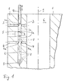
- the figures show the housing labeled 1 during manufacture before the closing mechanism is installed. In the illustrated case, the erosive aftertreatment of housing bores 2 - 5 previously drilled is carried out. In the method according to the invention, a special eroding electrode 10 is used in the exemplary embodiment.
- the housing 1 is made of metal, preferably a cut-to-length aluminum extrusion or aluminum die casting.
- the housing 1 shown only in sections is preferably cuboid with a square cross section perpendicular to the image plane in the figures.
- the bores produced with the method according to the invention are channels of the hydraulic circuit in the finished closer.
- a blind hole-like longitudinal bore 2 is shown as an example, which is crossed by two transverse bores 3, 4.
- the longitudinal bore 2 represents a typical deep hole with a relatively large length and small diameter.
- the transverse bores 3 and 4 are designed as shorter through bores. They lead from the outside of the housing into the cylindrical cavity 6. Between the transverse bores 3 and 4 there is a blind hole-like bore 5 with a larger diameter. It is used to hold a regulating valve. The bottom of the hole is tapered.
- the conical section of the bore 5 crosses the longitudinal bore 2. It serves to receive the valve cone of the regulating valve.
- the bores 2 - 4 are filled with hydraulic oil and form a closed hydraulic circuit inside the housing with the hydraulic oil in the cylinder space 6.
- the outer mouths of the bores 2, 3 and 4 are closed by pressed-in locking balls and the valve receiving bore 5 is also closed to the outside by the sealed regulating valve accommodated therein.
- Holes 2 - 5 are made in several steps.
- the longitudinal bore 2 is drilled as a deep hole.
- the deep hole drilling method used is known per se.
- a conventional deep hole drill can be used, which has a special cutting edge geometry and is hollow on the inside, for supplying the cooling medium.
- the drill works at high speed at high pressure.
- the chips are largely flushed out by the cooling medium.
- the transverse bores 3, 4 and the receiving bore 5 are then also drilled in a cutting manner, it being possible to use a conventional twist drill.
- burrs usually occur.
- Chips are also indicated. They are labeled 7. They float in the hole 2, a collection of chips 7 is arranged in the bottom 8 of the hole and some chips lie against the wall of the hole or are partially very firmly bonded to it, the dried cooling liquid from the previous drilling operation acting as an adhesive. The sticking of the chips is also one of the reasons why the chips cannot be removed by normal washing-out processes or by compressed air.
- Deburring and removal of the chips is done by erosive finishing.
- the specially constructed tube electrode 10 is used for eroding. Spark erosion or arc erosion is used.
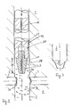
- the eroding electrode 10 has a feed channel 11 in the longitudinal central axis.
- the eroding electrode 10 is inserted vertically into the bore 12 from above.
- the housing 1 is arranged so that the bore 2 is aligned vertically with the opening at the top and bottom 8 of the bore.
- the electrode 11 shown in more detail in Figure 2 is tubular.
- the upper part consists of an electrically conductive tube which is electrically insulated on the circumference, e.g. B. with insulating varnish or through a thin plastic tube.
- the upper part consists of an aluminum tube 12 with an electrically insulating outer jacket 13 made of thick-film anodized.
- a separately formed eroding tip 14 is inserted.
- it is made of copper, but can in principle consist of all materials suitable for an eroding tool, for. B. graphite, W-Cu alloys etc.
- the eroding tip 14 On its longitudinal center axis it has a through-channel which, together with the inner channel of the tube 12, forms the feed channel 11 of the auxiliary medium, which emerges at the conically tapering free end of the eroding tip 14.
- the eroding tip 14 is subject to more or less severe wear and must therefore be exchangeable. In the arrangement described, this is simple and inexpensive to implement.
- the eroding tip 14 represents the active part of the electrode 10.
- the erosive degradation of the material takes place exclusively in the eroding area 15 along the eroding tip 14.
- the upper, electrically insulated part 12 of the electrode is inactive.
- An eroding electrode with the structure shown can be used both for arc eroding and for spark eroding.
- the electrode In arc erosion, it is provided that the electrode carries out high-frequency axial vibrations. It can also rotate about its longitudinal axis, but is preferably fixed.
- the electrode rotates about its longitudinal axis. Versions with a non-rotating electrode are also possible.
- the electrode 10 can be designed such that this working movement of the electrode, that is to say axial vibrations or rotations, is carried out by the entire electrode 10 or, in alternative embodiments, only by the eroding tip 14.
- the erosive processing is carried out as follows: The electrode 10 is inserted from above into the vertically aligned bore 2 with a predetermined axial feed.
- the auxiliary medium supplied through the inner electrode channel 11 continuously emerges from the lower end of the eroding tip 14 and flows upward between the inner wall of the bore 2 and the outer wall of the electrode 10.
- the auxiliary medium in the bore is under pressure (for spark erosion up to 100 bar, for arc erosion up to 10 bar). The high working pressure favors the rinsing effect.
- the erosive removal of the chips and burrs begins as soon as the active region 15 reaches a chip or burr that is in contact with the inner wall of the bore. Particles smaller than 100 ⁇ are created. The particles are rinsed out by the auxiliary medium.
- the electrode 10 can be switched in such a way that the feed rate is automatically reduced during the erosive removal and, as soon as there is no more erosion, the feed rate is increased again to the predetermined initial value.
- an optimal eroding gap is ensured since the diameter of the eroding tip 14 in the entire active region 15 is smaller than the diameter of the insulated tube 12 and the diameter of the tube 12 is matched to the diameter of the bore 2.
- the diameter of the tube 12 2.6 mm
- the largest upper diameter of the eroding tip 14 2.5 mm.
- the length of hole 2 is 145 mm.
- the chips 7, which are loosely arranged in the bore 2, are carried along by the electrode 10 as long as there is no contact with the bore wall required for eroding and are pushed together in the area of the bore base 8 and finally eroded as soon as the required contact with the bore wall occurs.
- the erosive removal takes place before the electrode 10 has reached its end position on the bottom 8 of the bore.
- the main active part is the conical section of the tip 14, since here the axial vibrations contribute to the gap change and support the arcing.
- the tip 14 can also be cylindrical, preferably for EDM machining.
- the cross holes 3 and 4 can also be reworked in a corresponding manner.
- the holes 3, 4 formed as through holes z. B. closed via a tool mandrel that can be inserted into the cylinder cavity 6.
- the mandrel can each have depressions in the region of the mouths opening into the cylinder space 6, which serve as a reservoir for receiving the auxiliary fluid.
- a correspondingly constructed electrode 10 can be used for eroding.
- any burrs in the mouth area of the bores 3, 4 in the cylinder space 6 are also removed.
- This erosive machining of the bores 3, 4 can take place before or after the erosive machining of the bore 2 described above.
- FIGS. 1 and 2 can also be used in the same or a corresponding manner in the production of housings of other hydraulic or pneumatic drives or door closers.
Landscapes
- Engineering & Computer Science (AREA)
- Physics & Mathematics (AREA)
- Mechanical Engineering (AREA)
- Thermal Sciences (AREA)
- Optics & Photonics (AREA)
- Plasma & Fusion (AREA)
- Electrical Discharge Machining, Electrochemical Machining, And Combined Machining (AREA)
Applications Claiming Priority (2)
| Application Number | Priority Date | Filing Date | Title |
|---|---|---|---|
| DE4012233 | 1990-04-14 | ||
| DE4012233 | 1990-04-14 |
Publications (2)
| Publication Number | Publication Date |
|---|---|
| EP0452798A2 true EP0452798A2 (fr) | 1991-10-23 |
| EP0452798A3 EP0452798A3 (en) | 1992-06-24 |
Family
ID=6404518
Family Applications (1)
| Application Number | Title | Priority Date | Filing Date |
|---|---|---|---|
| EP19910105721 Withdrawn EP0452798A3 (en) | 1990-04-14 | 1991-04-11 | Method for drilling a hole |
Country Status (1)
| Country | Link |
|---|---|
| EP (1) | EP0452798A3 (fr) |
Cited By (2)
| Publication number | Priority date | Publication date | Assignee | Title |
|---|---|---|---|---|
| EP1669157A1 (fr) * | 2004-12-07 | 2006-06-14 | Delphi Technologies, Inc. | Dispositif de perçage par laser d'un trou avec une tige et un élément de protection fixé à l'extrémité de la tige |
| WO2006131741A3 (fr) * | 2005-06-06 | 2007-03-08 | Delphi Tech Inc | Procede d'usinage |
Family Cites Families (5)
| Publication number | Priority date | Publication date | Assignee | Title |
|---|---|---|---|---|
| US3547798A (en) * | 1967-03-29 | 1970-12-15 | Cincinnati Milacron Inc | Electrochemical machining tool |
| US3753879A (en) * | 1971-02-03 | 1973-08-21 | Ass Eng Ltd | Method and means for producing holes |
| FR2547868B1 (fr) * | 1983-06-21 | 1985-12-27 | Gerard De Bruyn | Procede de fabrication d'une rampe d'injection d'essence, et rampe obtenue par ce procede |
| EP0299143A1 (fr) * | 1987-06-12 | 1989-01-18 | Raycon Textron Inc. | Installation de production pour percer par rayon laser et utilisation d'électro-érosion |
| DE3873331D1 (de) * | 1988-01-27 | 1992-09-03 | Inst Elektroniki Im U A Arifov | Vorrichtung zur elektroerosivon herstellung von loechern in werkstuecken. |
-
1991
- 1991-04-11 EP EP19910105721 patent/EP0452798A3/de not_active Withdrawn
Cited By (3)
| Publication number | Priority date | Publication date | Assignee | Title |
|---|---|---|---|---|
| EP1669157A1 (fr) * | 2004-12-07 | 2006-06-14 | Delphi Technologies, Inc. | Dispositif de perçage par laser d'un trou avec une tige et un élément de protection fixé à l'extrémité de la tige |
| WO2006131741A3 (fr) * | 2005-06-06 | 2007-03-08 | Delphi Tech Inc | Procede d'usinage |
| US8313636B2 (en) | 2005-06-06 | 2012-11-20 | Delphi Technologies Holding S.Arl | Machining method |
Also Published As
| Publication number | Publication date |
|---|---|
| EP0452798A3 (en) | 1992-06-24 |
Similar Documents
| Publication | Publication Date | Title |
|---|---|---|
| DE60018098T2 (de) | HERSTELLUNGSVERFAHREN EINES BOHRMEIßELS ZUM SCHLAGBOHREN UND BOHRMEIßEL UND HARTMETALLEINSÄTZE DAFÜR | |
| DE3601385C2 (fr) | ||
| EP0715055B1 (fr) | Outil avec corps de base et élément de coupe | |
| EP2298491B1 (fr) | Outil doté de canaux pour fluide de refroidissement | |
| EP1407848B1 (fr) | Outil de filetage avec refroidissement | |
| DE69619544T2 (de) | Bohrbuchseneinheit mit spanbrecher | |
| EP0223909A1 (fr) | Filière d'extrudeuse pour la fabrication d'une ébauche de foret en métal dur ou en céramique | |
| EP2635394B1 (fr) | Foret 3/4 | |
| EP1340573A1 (fr) | Procédé de fabrication pour un outil coupant, notamment un foret ou une fraise | |
| EP1420915B1 (fr) | Outil en forme de barre servant a l'usinage de pieces | |
| DE69613755T2 (de) | Verfahren zur Herstellung von Extrusionsdüsen | |
| DE102009043850A1 (de) | Werkzeug | |
| DE19942440A1 (de) | Bohrer und Wegwerfspitze zur Verwendung bei einem Bohrverfahren | |
| DE19800097A1 (de) | Span- oder Schneidwerkzeug und Verfahren zu dessen Herstellung | |
| EP1610919B2 (fr) | Foret a une levre et son procede de production | |
| WO2023083725A1 (fr) | Outil combiné de perçage et d'ébavurage | |
| DE10144241B4 (de) | Bohrer | |
| DE102004054587B3 (de) | Verfahren zum Herstellen von reproduzierbaren Mikrobohrungen sowie Vorrichtung dafür | |
| EP1042086A1 (fr) | Outil de per age pour machines-outils et son procede de production | |
| EP0112437A1 (fr) | Outil pour un traitement précis et finissage de coupes cylindriques | |
| DE3627798C2 (de) | Verfahren und Kombinationswerkzeug zum Herstellen von Gewindebohrungen | |
| DE2801459A1 (de) | Vorrichtung zum herstellen von waermeuebertragungsrohren | |
| DE10354000A1 (de) | Gewindebohrer mit einem mit einer diamantartigen Kohlenstoffbeschichtung beschichteten Gewindeabschnitt | |
| DE2821752A1 (de) | Verfahren zur herstellung von gekuehlten ventilen fuer brennkraftmaschinen und so erzielte ventile | |
| DE3314718A1 (de) | Tiefbohrwerkzeug und verfahren zu seiner herstellung |
Legal Events
| Date | Code | Title | Description |
|---|---|---|---|
| PUAI | Public reference made under article 153(3) epc to a published international application that has entered the european phase |
Free format text: ORIGINAL CODE: 0009012 |
|
| AK | Designated contracting states |
Kind code of ref document: A2 Designated state(s): AT BE CH DE DK ES FR GB GR IT LI NL SE |
|
| PUAL | Search report despatched |
Free format text: ORIGINAL CODE: 0009013 |
|
| AK | Designated contracting states |
Kind code of ref document: A3 Designated state(s): AT BE CH DE DK ES FR GB GR IT LI NL SE |
|
| 17P | Request for examination filed |
Effective date: 19921202 |
|
| 17Q | First examination report despatched |
Effective date: 19930607 |
|
| STAA | Information on the status of an ep patent application or granted ep patent |
Free format text: STATUS: THE APPLICATION IS DEEMED TO BE WITHDRAWN |
|
| 18D | Application deemed to be withdrawn |
Effective date: 19940705 |