EP0452811B1 - Package of photosensitive material - Google Patents
Package of photosensitive material Download PDFInfo
- Publication number
- EP0452811B1 EP0452811B1 EP19910105765 EP91105765A EP0452811B1 EP 0452811 B1 EP0452811 B1 EP 0452811B1 EP 19910105765 EP19910105765 EP 19910105765 EP 91105765 A EP91105765 A EP 91105765A EP 0452811 B1 EP0452811 B1 EP 0452811B1
- Authority
- EP
- European Patent Office
- Prior art keywords
- film
- cartridge
- silver
- spool
- layer
- Prior art date
- Legal status (The legal status is an assumption and is not a legal conclusion. Google has not performed a legal analysis and makes no representation as to the accuracy of the status listed.)
- Expired - Lifetime
Links
- 239000000463 material Substances 0.000 title description 15
- 239000000839 emulsion Substances 0.000 claims description 61
- 229910052709 silver Inorganic materials 0.000 claims description 55
- 239000004332 silver Substances 0.000 claims description 55
- -1 silver halide Chemical class 0.000 claims description 55
- BQCADISMDOOEFD-UHFFFAOYSA-N Silver Chemical compound [Ag] BQCADISMDOOEFD-UHFFFAOYSA-N 0.000 claims description 24
- 150000001875 compounds Chemical class 0.000 claims description 22
- 239000011800 void material Substances 0.000 claims description 13
- 125000003118 aryl group Chemical group 0.000 claims description 6
- 125000000623 heterocyclic group Chemical group 0.000 claims description 5
- 125000004435 hydrogen atom Chemical group [H]* 0.000 claims description 5
- JKFYKCYQEWQPTM-UHFFFAOYSA-N 2-azaniumyl-2-(4-fluorophenyl)acetate Chemical compound OC(=O)C(N)C1=CC=C(F)C=C1 JKFYKCYQEWQPTM-UHFFFAOYSA-N 0.000 claims description 4
- 229910021612 Silver iodide Inorganic materials 0.000 claims description 4
- 125000001931 aliphatic group Chemical group 0.000 claims description 4
- 229910052783 alkali metal Inorganic materials 0.000 claims description 4
- 150000001340 alkali metals Chemical group 0.000 claims description 4
- 125000001453 quaternary ammonium group Chemical group 0.000 claims description 4
- ZUNKMNLKJXRCDM-UHFFFAOYSA-N silver bromoiodide Chemical compound [Ag].IBr ZUNKMNLKJXRCDM-UHFFFAOYSA-N 0.000 claims description 4
- 229940045105 silver iodide Drugs 0.000 claims description 4
- 125000005496 phosphonium group Chemical group 0.000 claims description 3
- HOLVRJRSWZOAJU-UHFFFAOYSA-N [Ag].ICl Chemical compound [Ag].ICl HOLVRJRSWZOAJU-UHFFFAOYSA-N 0.000 claims description 2
- 239000010410 layer Substances 0.000 description 114
- 230000035945 sensitivity Effects 0.000 description 21
- 230000001235 sensitizing effect Effects 0.000 description 19
- XLYOFNOQVPJJNP-UHFFFAOYSA-N water Substances O XLYOFNOQVPJJNP-UHFFFAOYSA-N 0.000 description 18
- 108010010803 Gelatin Proteins 0.000 description 17
- 229920000159 gelatin Polymers 0.000 description 17
- 239000008273 gelatin Substances 0.000 description 17
- 235000019322 gelatine Nutrition 0.000 description 17
- 235000011852 gelatine desserts Nutrition 0.000 description 17
- 238000000034 method Methods 0.000 description 17
- 239000000975 dye Substances 0.000 description 10
- 239000012452 mother liquor Substances 0.000 description 9
- 239000000084 colloidal system Substances 0.000 description 8
- 238000011160 research Methods 0.000 description 8
- 230000006866 deterioration Effects 0.000 description 7
- 238000005406 washing Methods 0.000 description 7
- 239000013078 crystal Substances 0.000 description 6
- 239000000203 mixture Substances 0.000 description 6
- GEHJYWRUCIMESM-UHFFFAOYSA-L sodium sulfite Chemical compound [Na+].[Na+].[O-]S([O-])=O GEHJYWRUCIMESM-UHFFFAOYSA-L 0.000 description 6
- WSFSSNUMVMOOMR-UHFFFAOYSA-N Formaldehyde Chemical compound O=C WSFSSNUMVMOOMR-UHFFFAOYSA-N 0.000 description 5
- 239000011248 coating agent Substances 0.000 description 5
- 238000000576 coating method Methods 0.000 description 5
- 238000011161 development Methods 0.000 description 5
- 239000003112 inhibitor Substances 0.000 description 5
- 239000003109 Disodium ethylene diamine tetraacetate Substances 0.000 description 4
- ZGTMUACCHSMWAC-UHFFFAOYSA-L EDTA disodium salt (anhydrous) Chemical compound [Na+].[Na+].OC(=O)CN(CC([O-])=O)CCN(CC(O)=O)CC([O-])=O ZGTMUACCHSMWAC-UHFFFAOYSA-L 0.000 description 4
- 239000000654 additive Substances 0.000 description 4
- 125000000217 alkyl group Chemical group 0.000 description 4
- 238000009835 boiling Methods 0.000 description 4
- 229910052799 carbon Inorganic materials 0.000 description 4
- 229920001429 chelating resin Polymers 0.000 description 4
- DOIRQSBPFJWKBE-UHFFFAOYSA-N dibutyl phthalate Chemical compound CCCCOC(=O)C1=CC=CC=C1C(=O)OCCCC DOIRQSBPFJWKBE-UHFFFAOYSA-N 0.000 description 4
- 235000019301 disodium ethylene diamine tetraacetate Nutrition 0.000 description 4
- 239000006185 dispersion Substances 0.000 description 4
- 238000002360 preparation method Methods 0.000 description 4
- 238000004804 winding Methods 0.000 description 4
- ZWEHNKRNPOVVGH-UHFFFAOYSA-N 2-Butanone Chemical compound CCC(C)=O ZWEHNKRNPOVVGH-UHFFFAOYSA-N 0.000 description 3
- XEKOWRVHYACXOJ-UHFFFAOYSA-N Ethyl acetate Chemical compound CCOC(C)=O XEKOWRVHYACXOJ-UHFFFAOYSA-N 0.000 description 3
- PEDCQBHIVMGVHV-UHFFFAOYSA-N Glycerine Chemical compound OCC(O)CO PEDCQBHIVMGVHV-UHFFFAOYSA-N 0.000 description 3
- ZMXDDKWLCZADIW-UHFFFAOYSA-N N,N-Dimethylformamide Chemical compound CN(C)C=O ZMXDDKWLCZADIW-UHFFFAOYSA-N 0.000 description 3
- 125000003545 alkoxy group Chemical group 0.000 description 3
- 239000011230 binding agent Substances 0.000 description 3
- 238000004061 bleaching Methods 0.000 description 3
- 125000004432 carbon atom Chemical group C* 0.000 description 3
- 239000003795 chemical substances by application Substances 0.000 description 3
- 230000000694 effects Effects 0.000 description 3
- 239000007789 gas Substances 0.000 description 3
- 125000002887 hydroxy group Chemical group [H]O* 0.000 description 3
- 239000007788 liquid Substances 0.000 description 3
- 125000001997 phenyl group Chemical group [H]C1=C([H])C([H])=C(*)C([H])=C1[H] 0.000 description 3
- NLKNQRATVPKPDG-UHFFFAOYSA-M potassium iodide Chemical compound [K+].[I-] NLKNQRATVPKPDG-UHFFFAOYSA-M 0.000 description 3
- 235000010265 sodium sulphite Nutrition 0.000 description 3
- 239000003381 stabilizer Substances 0.000 description 3
- NWUYHJFMYQTDRP-UHFFFAOYSA-N 1,2-bis(ethenyl)benzene;1-ethenyl-2-ethylbenzene;styrene Chemical compound C=CC1=CC=CC=C1.CCC1=CC=CC=C1C=C.C=CC1=CC=CC=C1C=C NWUYHJFMYQTDRP-UHFFFAOYSA-N 0.000 description 2
- WNWHHMBRJJOGFJ-UHFFFAOYSA-N 16-methylheptadecan-1-ol Chemical compound CC(C)CCCCCCCCCCCCCCCO WNWHHMBRJJOGFJ-UHFFFAOYSA-N 0.000 description 2
- 125000004070 6 membered heterocyclic group Chemical group 0.000 description 2
- VHUUQVKOLVNVRT-UHFFFAOYSA-N Ammonium hydroxide Chemical compound [NH4+].[OH-] VHUUQVKOLVNVRT-UHFFFAOYSA-N 0.000 description 2
- OYPRJOBELJOOCE-UHFFFAOYSA-N Calcium Chemical compound [Ca] OYPRJOBELJOOCE-UHFFFAOYSA-N 0.000 description 2
- 229920002284 Cellulose triacetate Polymers 0.000 description 2
- RTZKZFJDLAIYFH-UHFFFAOYSA-N Diethyl ether Chemical compound CCOCC RTZKZFJDLAIYFH-UHFFFAOYSA-N 0.000 description 2
- JOYRKODLDBILNP-UHFFFAOYSA-N Ethyl urethane Chemical compound CCOC(N)=O JOYRKODLDBILNP-UHFFFAOYSA-N 0.000 description 2
- 101000618467 Hypocrea jecorina (strain ATCC 56765 / BCRC 32924 / NRRL 11460 / Rut C-30) Endo-1,4-beta-xylanase 2 Proteins 0.000 description 2
- JLVVSXFLKOJNIY-UHFFFAOYSA-N Magnesium ion Chemical compound [Mg+2] JLVVSXFLKOJNIY-UHFFFAOYSA-N 0.000 description 2
- CWNSVVHTTQBGQB-UHFFFAOYSA-N N,N-Diethyldodecanamide Chemical compound CCCCCCCCCCCC(=O)N(CC)CC CWNSVVHTTQBGQB-UHFFFAOYSA-N 0.000 description 2
- 239000004698 Polyethylene Substances 0.000 description 2
- 239000004743 Polypropylene Substances 0.000 description 2
- PMZURENOXWZQFD-UHFFFAOYSA-L Sodium Sulfate Chemical compound [Na+].[Na+].[O-]S([O-])(=O)=O PMZURENOXWZQFD-UHFFFAOYSA-L 0.000 description 2
- YSMRWXYRXBRSND-UHFFFAOYSA-N TOTP Chemical compound CC1=CC=CC=C1OP(=O)(OC=1C(=CC=CC=1)C)OC1=CC=CC=C1C YSMRWXYRXBRSND-UHFFFAOYSA-N 0.000 description 2
- NNLVGZFZQQXQNW-ADJNRHBOSA-N [(2r,3r,4s,5r,6s)-4,5-diacetyloxy-3-[(2s,3r,4s,5r,6r)-3,4,5-triacetyloxy-6-(acetyloxymethyl)oxan-2-yl]oxy-6-[(2r,3r,4s,5r,6s)-4,5,6-triacetyloxy-2-(acetyloxymethyl)oxan-3-yl]oxyoxan-2-yl]methyl acetate Chemical compound O([C@@H]1O[C@@H]([C@H]([C@H](OC(C)=O)[C@H]1OC(C)=O)O[C@H]1[C@@H]([C@@H](OC(C)=O)[C@H](OC(C)=O)[C@@H](COC(C)=O)O1)OC(C)=O)COC(=O)C)[C@@H]1[C@@H](COC(C)=O)O[C@@H](OC(C)=O)[C@H](OC(C)=O)[C@H]1OC(C)=O NNLVGZFZQQXQNW-ADJNRHBOSA-N 0.000 description 2
- 239000006096 absorbing agent Substances 0.000 description 2
- 238000010521 absorption reaction Methods 0.000 description 2
- 230000002378 acidificating effect Effects 0.000 description 2
- 125000004453 alkoxycarbonyl group Chemical group 0.000 description 2
- 125000004414 alkyl thio group Chemical group 0.000 description 2
- 125000003277 amino group Chemical group 0.000 description 2
- QGZKDVFQNNGYKY-UHFFFAOYSA-N ammonia Natural products N QGZKDVFQNNGYKY-UHFFFAOYSA-N 0.000 description 2
- XYXNTHIYBIDHGM-UHFFFAOYSA-N ammonium thiosulfate Chemical compound [NH4+].[NH4+].[O-]S([O-])(=O)=S XYXNTHIYBIDHGM-UHFFFAOYSA-N 0.000 description 2
- 239000003957 anion exchange resin Substances 0.000 description 2
- 125000003354 benzotriazolyl group Chemical group N1N=NC2=C1C=CC=C2* 0.000 description 2
- 239000011575 calcium Substances 0.000 description 2
- 229910001424 calcium ion Inorganic materials 0.000 description 2
- 125000003917 carbamoyl group Chemical group [H]N([H])C(*)=O 0.000 description 2
- 125000003178 carboxy group Chemical group [H]OC(*)=O 0.000 description 2
- 239000003729 cation exchange resin Substances 0.000 description 2
- 238000005859 coupling reaction Methods 0.000 description 2
- 125000004093 cyano group Chemical group *C#N 0.000 description 2
- JHIVVAPYMSGYDF-UHFFFAOYSA-N cyclohexanone Chemical compound O=C1CCCCC1 JHIVVAPYMSGYDF-UHFFFAOYSA-N 0.000 description 2
- CEJLBZWIKQJOAT-UHFFFAOYSA-N dichloroisocyanuric acid Chemical compound ClN1C(=O)NC(=O)N(Cl)C1=O CEJLBZWIKQJOAT-UHFFFAOYSA-N 0.000 description 2
- 238000001035 drying Methods 0.000 description 2
- FKRCODPIKNYEAC-UHFFFAOYSA-N ethyl propionate Chemical compound CCOC(=O)CC FKRCODPIKNYEAC-UHFFFAOYSA-N 0.000 description 2
- 239000007850 fluorescent dye Substances 0.000 description 2
- 125000005843 halogen group Chemical group 0.000 description 2
- 229920000126 latex Polymers 0.000 description 2
- 229910001425 magnesium ion Inorganic materials 0.000 description 2
- 229910052757 nitrogen Inorganic materials 0.000 description 2
- 239000003960 organic solvent Substances 0.000 description 2
- 230000002093 peripheral effect Effects 0.000 description 2
- 229920000573 polyethylene Polymers 0.000 description 2
- 239000004848 polyfunctional curative Substances 0.000 description 2
- 229920001155 polypropylene Polymers 0.000 description 2
- 229920000915 polyvinyl chloride Polymers 0.000 description 2
- 239000004800 polyvinyl chloride Substances 0.000 description 2
- IOLCXVTUBQKXJR-UHFFFAOYSA-M potassium bromide Chemical compound [K+].[Br-] IOLCXVTUBQKXJR-UHFFFAOYSA-M 0.000 description 2
- BWHMMNNQKKPAPP-UHFFFAOYSA-L potassium carbonate Chemical compound [K+].[K+].[O-]C([O-])=O BWHMMNNQKKPAPP-UHFFFAOYSA-L 0.000 description 2
- 238000012545 processing Methods 0.000 description 2
- 239000011241 protective layer Substances 0.000 description 2
- 150000003839 salts Chemical class 0.000 description 2
- 238000007789 sealing Methods 0.000 description 2
- 238000000926 separation method Methods 0.000 description 2
- 229910052938 sodium sulfate Inorganic materials 0.000 description 2
- 235000011152 sodium sulphate Nutrition 0.000 description 2
- 239000002904 solvent Substances 0.000 description 2
- 230000006641 stabilisation Effects 0.000 description 2
- 238000011105 stabilization Methods 0.000 description 2
- 230000000087 stabilizing effect Effects 0.000 description 2
- 230000008961 swelling Effects 0.000 description 2
- 238000012360 testing method Methods 0.000 description 2
- GVEYRUKUJCHJSR-UHFFFAOYSA-N (4-azaniumyl-3-methylphenyl)-ethyl-(2-hydroxyethyl)azanium;sulfate Chemical compound OS(O)(=O)=O.OCCN(CC)C1=CC=C(N)C(C)=C1 GVEYRUKUJCHJSR-UHFFFAOYSA-N 0.000 description 1
- LOOCNDFTHKSTFY-UHFFFAOYSA-N 1,1,2-trichloropropyl dihydrogen phosphate Chemical compound CC(Cl)C(Cl)(Cl)OP(O)(O)=O LOOCNDFTHKSTFY-UHFFFAOYSA-N 0.000 description 1
- IAUKWGFWINVWKS-UHFFFAOYSA-N 1,2-di(propan-2-yl)naphthalene Chemical compound C1=CC=CC2=C(C(C)C)C(C(C)C)=CC=C21 IAUKWGFWINVWKS-UHFFFAOYSA-N 0.000 description 1
- ZRHUHDUEXWHZMA-UHFFFAOYSA-N 1,4-dihydropyrazol-5-one Chemical compound O=C1CC=NN1 ZRHUHDUEXWHZMA-UHFFFAOYSA-N 0.000 description 1
- RWKSBJVOQGKDFZ-UHFFFAOYSA-N 16-methylheptadecyl 2-hydroxypropanoate Chemical compound CC(C)CCCCCCCCCCCCCCCOC(=O)C(C)O RWKSBJVOQGKDFZ-UHFFFAOYSA-N 0.000 description 1
- WMVJWKURWRGJCI-UHFFFAOYSA-N 2,4-bis(2-methylbutan-2-yl)phenol Chemical compound CCC(C)(C)C1=CC=C(O)C(C(C)(C)CC)=C1 WMVJWKURWRGJCI-UHFFFAOYSA-N 0.000 description 1
- PAWQVTBBRAZDMG-UHFFFAOYSA-N 2-(3-bromo-2-fluorophenyl)acetic acid Chemical compound OC(=O)CC1=CC=CC(Br)=C1F PAWQVTBBRAZDMG-UHFFFAOYSA-N 0.000 description 1
- VTIMKVIDORQQFA-UHFFFAOYSA-N 2-Ethylhexyl-4-hydroxybenzoate Chemical compound CCCCC(CC)COC(=O)C1=CC=C(O)C=C1 VTIMKVIDORQQFA-UHFFFAOYSA-N 0.000 description 1
- SVONRAPFKPVNKG-UHFFFAOYSA-N 2-ethoxyethyl acetate Chemical compound CCOCCOC(C)=O SVONRAPFKPVNKG-UHFFFAOYSA-N 0.000 description 1
- UADWUILHKRXHMM-UHFFFAOYSA-N 2-ethylhexyl benzoate Chemical compound CCCCC(CC)COC(=O)C1=CC=CC=C1 UADWUILHKRXHMM-UHFFFAOYSA-N 0.000 description 1
- 229940106004 2-ethylhexyl benzoate Drugs 0.000 description 1
- 125000002373 5 membered heterocyclic group Chemical group 0.000 description 1
- QGZKDVFQNNGYKY-UHFFFAOYSA-O Ammonium Chemical compound [NH4+] QGZKDVFQNNGYKY-UHFFFAOYSA-O 0.000 description 1
- DKPFZGUDAPQIHT-UHFFFAOYSA-N Butyl acetate Natural products CCCCOC(C)=O DKPFZGUDAPQIHT-UHFFFAOYSA-N 0.000 description 1
- GAWIXWVDTYZWAW-UHFFFAOYSA-N C[CH]O Chemical group C[CH]O GAWIXWVDTYZWAW-UHFFFAOYSA-N 0.000 description 1
- ZAMOUSCENKQFHK-UHFFFAOYSA-N Chlorine atom Chemical group [Cl] ZAMOUSCENKQFHK-UHFFFAOYSA-N 0.000 description 1
- 239000004803 Di-2ethylhexylphthalate Substances 0.000 description 1
- PGIBJVOPLXHHGS-UHFFFAOYSA-N Di-n-decyl phthalate Chemical compound CCCCCCCCCCOC(=O)C1=CC=CC=C1C(=O)OCCCCCCCCCC PGIBJVOPLXHHGS-UHFFFAOYSA-N 0.000 description 1
- VOWAEIGWURALJQ-UHFFFAOYSA-N Dicyclohexyl phthalate Chemical compound C=1C=CC=C(C(=O)OC2CCCCC2)C=1C(=O)OC1CCCCC1 VOWAEIGWURALJQ-UHFFFAOYSA-N 0.000 description 1
- RWSOTUBLDIXVET-UHFFFAOYSA-N Dihydrogen sulfide Chemical class S RWSOTUBLDIXVET-UHFFFAOYSA-N 0.000 description 1
- LFQSCWFLJHTTHZ-UHFFFAOYSA-N Ethanol Chemical compound CCO LFQSCWFLJHTTHZ-UHFFFAOYSA-N 0.000 description 1
- DBVJJBKOTRCVKF-UHFFFAOYSA-N Etidronic acid Chemical compound OP(=O)(O)C(O)(C)P(O)(O)=O DBVJJBKOTRCVKF-UHFFFAOYSA-N 0.000 description 1
- PXGOKWXKJXAPGV-UHFFFAOYSA-N Fluorine Chemical group FF PXGOKWXKJXAPGV-UHFFFAOYSA-N 0.000 description 1
- DGAQECJNVWCQMB-PUAWFVPOSA-M Ilexoside XXIX Chemical compound C[C@@H]1CC[C@@]2(CC[C@@]3(C(=CC[C@H]4[C@]3(CC[C@@H]5[C@@]4(CC[C@@H](C5(C)C)OS(=O)(=O)[O-])C)C)[C@@H]2[C@]1(C)O)C)C(=O)O[C@H]6[C@@H]([C@H]([C@@H]([C@H](O6)CO)O)O)O.[Na+] DGAQECJNVWCQMB-PUAWFVPOSA-M 0.000 description 1
- WHXSMMKQMYFTQS-UHFFFAOYSA-N Lithium Chemical compound [Li] WHXSMMKQMYFTQS-UHFFFAOYSA-N 0.000 description 1
- QPCDCPDFJACHGM-UHFFFAOYSA-N N,N-bis{2-[bis(carboxymethyl)amino]ethyl}glycine Chemical compound OC(=O)CN(CC(O)=O)CCN(CC(=O)O)CCN(CC(O)=O)CC(O)=O QPCDCPDFJACHGM-UHFFFAOYSA-N 0.000 description 1
- CGSLYBDCEGBZCG-UHFFFAOYSA-N Octicizer Chemical compound C=1C=CC=CC=1OP(=O)(OCC(CC)CCCC)OC1=CC=CC=C1 CGSLYBDCEGBZCG-UHFFFAOYSA-N 0.000 description 1
- 229910019142 PO4 Inorganic materials 0.000 description 1
- ABLZXFCXXLZCGV-UHFFFAOYSA-N Phosphorous acid Chemical class OP(O)=O ABLZXFCXXLZCGV-UHFFFAOYSA-N 0.000 description 1
- ZLMJMSJWJFRBEC-UHFFFAOYSA-N Potassium Chemical compound [K] ZLMJMSJWJFRBEC-UHFFFAOYSA-N 0.000 description 1
- DWAQJAXMDSEUJJ-UHFFFAOYSA-M Sodium bisulfite Chemical compound [Na+].OS([O-])=O DWAQJAXMDSEUJJ-UHFFFAOYSA-M 0.000 description 1
- 125000000738 acetamido group Chemical group [H]C([H])([H])C(=O)N([H])[*] 0.000 description 1
- 125000004442 acylamino group Chemical group 0.000 description 1
- 230000000996 additive effect Effects 0.000 description 1
- 150000001298 alcohols Chemical class 0.000 description 1
- 229910001413 alkali metal ion Inorganic materials 0.000 description 1
- 125000003342 alkenyl group Chemical group 0.000 description 1
- 125000005115 alkyl carbamoyl group Chemical group 0.000 description 1
- 125000005153 alkyl sulfamoyl group Chemical group 0.000 description 1
- 125000005422 alkyl sulfonamido group Chemical group 0.000 description 1
- 125000004390 alkyl sulfonyl group Chemical group 0.000 description 1
- 125000000304 alkynyl group Chemical group 0.000 description 1
- 150000001408 amides Chemical class 0.000 description 1
- 125000004397 aminosulfonyl group Chemical group NS(=O)(=O)* 0.000 description 1
- SWLVFNYSXGMGBS-UHFFFAOYSA-N ammonium bromide Chemical compound [NH4+].[Br-] SWLVFNYSXGMGBS-UHFFFAOYSA-N 0.000 description 1
- 150000001448 anilines Chemical class 0.000 description 1
- 230000000845 anti-microbial effect Effects 0.000 description 1
- 239000002216 antistatic agent Substances 0.000 description 1
- 125000005116 aryl carbamoyl group Chemical group 0.000 description 1
- 125000005421 aryl sulfonamido group Chemical group 0.000 description 1
- 125000004391 aryl sulfonyl group Chemical group 0.000 description 1
- 125000005110 aryl thio group Chemical group 0.000 description 1
- 125000004104 aryloxy group Chemical group 0.000 description 1
- XNSQZBOCSSMHSZ-UHFFFAOYSA-K azane;2-[2-[bis(carboxylatomethyl)amino]ethyl-(carboxymethyl)amino]acetate;iron(3+) Chemical compound [NH4+].[Fe+3].[O-]C(=O)CN(CC([O-])=O)CCN(CC([O-])=O)CC([O-])=O XNSQZBOCSSMHSZ-UHFFFAOYSA-K 0.000 description 1
- 150000001556 benzimidazoles Chemical group 0.000 description 1
- UADWUILHKRXHMM-ZDUSSCGKSA-N benzoflex 181 Natural products CCCC[C@H](CC)COC(=O)C1=CC=CC=C1 UADWUILHKRXHMM-ZDUSSCGKSA-N 0.000 description 1
- 150000001558 benzoic acid derivatives Chemical class 0.000 description 1
- 125000001797 benzyl group Chemical group [H]C1=C([H])C([H])=C(C([H])=C1[H])C([H])([H])* 0.000 description 1
- 230000015572 biosynthetic process Effects 0.000 description 1
- BJQHLKABXJIVAM-UHFFFAOYSA-N bis(2-ethylhexyl) phthalate Chemical compound CCCCC(CC)COC(=O)C1=CC=CC=C1C(=O)OCC(CC)CCCC BJQHLKABXJIVAM-UHFFFAOYSA-N 0.000 description 1
- DTWCQJZIAHGJJX-UHFFFAOYSA-N bis[2,4-bis(2-methylbutan-2-yl)phenyl] benzene-1,2-dicarboxylate Chemical compound CCC(C)(C)C1=CC(C(C)(C)CC)=CC=C1OC(=O)C1=CC=CC=C1C(=O)OC1=CC=C(C(C)(C)CC)C=C1C(C)(C)CC DTWCQJZIAHGJJX-UHFFFAOYSA-N 0.000 description 1
- UEJPXAVHAFEXQR-UHFFFAOYSA-N bis[2,4-bis(2-methylbutan-2-yl)phenyl] benzene-1,3-dicarboxylate Chemical compound CCC(C)(C)C1=CC(C(C)(C)CC)=CC=C1OC(=O)C1=CC=CC(C(=O)OC=2C(=CC(=CC=2)C(C)(C)CC)C(C)(C)CC)=C1 UEJPXAVHAFEXQR-UHFFFAOYSA-N 0.000 description 1
- 238000005282 brightening Methods 0.000 description 1
- GDTBXPJZTBHREO-UHFFFAOYSA-N bromine Chemical group BrBr GDTBXPJZTBHREO-UHFFFAOYSA-N 0.000 description 1
- 229910052794 bromium Chemical group 0.000 description 1
- 150000001768 cations Chemical class 0.000 description 1
- 238000006243 chemical reaction Methods 0.000 description 1
- 239000000460 chlorine Chemical group 0.000 description 1
- 229910052801 chlorine Inorganic materials 0.000 description 1
- 210000000078 claw Anatomy 0.000 description 1
- 238000010276 construction Methods 0.000 description 1
- 230000008878 coupling Effects 0.000 description 1
- 238000010168 coupling process Methods 0.000 description 1
- 230000007423 decrease Effects 0.000 description 1
- 125000005117 dialkylcarbamoyl group Chemical group 0.000 description 1
- 229960002380 dibutyl phthalate Drugs 0.000 description 1
- XWVQUJDBOICHGH-UHFFFAOYSA-N dioctyl nonanedioate Chemical compound CCCCCCCCOC(=O)CCCCCCCC(=O)OCCCCCCCC XWVQUJDBOICHGH-UHFFFAOYSA-N 0.000 description 1
- VJHINFRRDQUWOJ-UHFFFAOYSA-N dioctyl sebacate Chemical compound CCCCC(CC)COC(=O)CCCCCCCCC(=O)OCC(CC)CCCC VJHINFRRDQUWOJ-UHFFFAOYSA-N 0.000 description 1
- DLAHAXOYRFRPFQ-UHFFFAOYSA-N dodecyl benzoate Chemical compound CCCCCCCCCCCCOC(=O)C1=CC=CC=C1 DLAHAXOYRFRPFQ-UHFFFAOYSA-N 0.000 description 1
- 229940106055 dodecyl benzoate Drugs 0.000 description 1
- KWKXNDCHNDYVRT-UHFFFAOYSA-N dodecylbenzene Chemical compound CCCCCCCCCCCCC1=CC=CC=C1 KWKXNDCHNDYVRT-UHFFFAOYSA-N 0.000 description 1
- 125000001495 ethyl group Chemical group [H]C([H])([H])C([H])([H])* 0.000 description 1
- 229910052731 fluorine Inorganic materials 0.000 description 1
- 239000011737 fluorine Substances 0.000 description 1
- 125000005842 heteroatom Chemical group 0.000 description 1
- FUZZWVXGSFPDMH-UHFFFAOYSA-N hexanoic acid Chemical compound CCCCCC(O)=O FUZZWVXGSFPDMH-UHFFFAOYSA-N 0.000 description 1
- 229930195733 hydrocarbon Natural products 0.000 description 1
- 150000002430 hydrocarbons Chemical class 0.000 description 1
- 229910000378 hydroxylammonium sulfate Inorganic materials 0.000 description 1
- 238000005470 impregnation Methods 0.000 description 1
- 238000010348 incorporation Methods 0.000 description 1
- 238000011835 investigation Methods 0.000 description 1
- 150000002503 iridium Chemical class 0.000 description 1
- 150000002505 iron Chemical class 0.000 description 1
- 230000001788 irregular Effects 0.000 description 1
- 239000004816 latex Substances 0.000 description 1
- 229910000464 lead oxide Inorganic materials 0.000 description 1
- 239000003446 ligand Substances 0.000 description 1
- 229910052744 lithium Inorganic materials 0.000 description 1
- 239000000314 lubricant Substances 0.000 description 1
- 238000004519 manufacturing process Methods 0.000 description 1
- WSFSSNUMVMOOMR-NJFSPNSNSA-N methanone Chemical compound O=[14CH2] WSFSSNUMVMOOMR-NJFSPNSNSA-N 0.000 description 1
- 125000001160 methoxycarbonyl group Chemical group [H]C([H])([H])OC(*)=O 0.000 description 1
- 125000002496 methyl group Chemical group [H]C([H])([H])* 0.000 description 1
- GRVDJDISBSALJP-UHFFFAOYSA-N methyloxidanyl Chemical group [O]C GRVDJDISBSALJP-UHFFFAOYSA-N 0.000 description 1
- 125000002816 methylsulfanyl group Chemical group [H]C([H])([H])S[*] 0.000 description 1
- 125000004170 methylsulfonyl group Chemical group [H]C([H])([H])S(*)(=O)=O 0.000 description 1
- 238000002156 mixing Methods 0.000 description 1
- 125000001624 naphthyl group Chemical group 0.000 description 1
- 125000000449 nitro group Chemical group [O-][N+](*)=O 0.000 description 1
- 125000004433 nitrogen atom Chemical group N* 0.000 description 1
- 239000002667 nucleating agent Substances 0.000 description 1
- YEXPOXQUZXUXJW-UHFFFAOYSA-N oxolead Chemical compound [Pb]=O YEXPOXQUZXUXJW-UHFFFAOYSA-N 0.000 description 1
- 229910052760 oxygen Inorganic materials 0.000 description 1
- 239000012188 paraffin wax Substances 0.000 description 1
- 229960003330 pentetic acid Drugs 0.000 description 1
- 230000035699 permeability Effects 0.000 description 1
- ISWSIDIOOBJBQZ-UHFFFAOYSA-N phenol group Chemical group C1(=CC=CC=C1)O ISWSIDIOOBJBQZ-UHFFFAOYSA-N 0.000 description 1
- 150000002989 phenols Chemical class 0.000 description 1
- 125000003356 phenylsulfanyl group Chemical group [*]SC1=C([H])C([H])=C([H])C([H])=C1[H] 0.000 description 1
- 125000003170 phenylsulfonyl group Chemical group C1(=CC=CC=C1)S(=O)(=O)* 0.000 description 1
- 235000021317 phosphate Nutrition 0.000 description 1
- 150000003013 phosphoric acid derivatives Chemical class 0.000 description 1
- 125000005498 phthalate group Chemical class 0.000 description 1
- XNGIFLGASWRNHJ-UHFFFAOYSA-L phthalate(2-) Chemical compound [O-]C(=O)C1=CC=CC=C1C([O-])=O XNGIFLGASWRNHJ-UHFFFAOYSA-L 0.000 description 1
- 239000004033 plastic Substances 0.000 description 1
- 229920003023 plastic Polymers 0.000 description 1
- 239000004014 plasticizer Substances 0.000 description 1
- 150000003057 platinum Chemical class 0.000 description 1
- 229920006267 polyester film Polymers 0.000 description 1
- 238000006116 polymerization reaction Methods 0.000 description 1
- 229910052700 potassium Inorganic materials 0.000 description 1
- 239000011591 potassium Substances 0.000 description 1
- 229910000027 potassium carbonate Inorganic materials 0.000 description 1
- 239000002243 precursor Substances 0.000 description 1
- 238000003825 pressing Methods 0.000 description 1
- GZTPJDLYPMPRDF-UHFFFAOYSA-N pyrrolo[3,2-c]pyrazole Chemical compound N1=NC2=CC=NC2=C1 GZTPJDLYPMPRDF-UHFFFAOYSA-N 0.000 description 1
- 239000011347 resin Substances 0.000 description 1
- 229920005989 resin Polymers 0.000 description 1
- 150000003283 rhodium Chemical class 0.000 description 1
- 229920006395 saturated elastomer Polymers 0.000 description 1
- 238000012216 screening Methods 0.000 description 1
- 229910052711 selenium Inorganic materials 0.000 description 1
- 239000002356 single layer Substances 0.000 description 1
- 229910052708 sodium Inorganic materials 0.000 description 1
- 239000011734 sodium Substances 0.000 description 1
- 229940079827 sodium hydrogen sulfite Drugs 0.000 description 1
- 235000010267 sodium hydrogen sulphite Nutrition 0.000 description 1
- UWSAIOMORQUEHN-UHFFFAOYSA-L sodium;2-[2-[carboxylatomethyl(carboxymethyl)amino]ethyl-(carboxymethyl)amino]acetate;iron(5+) Chemical compound [Na+].[Fe+5].OC(=O)CN(CC([O-])=O)CCN(CC(O)=O)CC([O-])=O UWSAIOMORQUEHN-UHFFFAOYSA-L 0.000 description 1
- SDKPSXWGRWWLKR-UHFFFAOYSA-M sodium;9,10-dioxoanthracene-1-sulfonate Chemical compound [Na+].O=C1C2=CC=CC=C2C(=O)C2=C1C=CC=C2S(=O)(=O)[O-] SDKPSXWGRWWLKR-UHFFFAOYSA-M 0.000 description 1
- 230000003595 spectral effect Effects 0.000 description 1
- 238000003860 storage Methods 0.000 description 1
- 239000000126 substance Substances 0.000 description 1
- 125000001424 substituent group Chemical group 0.000 description 1
- 125000005415 substituted alkoxy group Chemical group 0.000 description 1
- 125000000547 substituted alkyl group Chemical group 0.000 description 1
- 125000000020 sulfo group Chemical group O=S(=O)([*])O[H] 0.000 description 1
- 229910052717 sulfur Inorganic materials 0.000 description 1
- 239000004094 surface-active agent Substances 0.000 description 1
- IELLVVGAXDLVSW-UHFFFAOYSA-N tricyclohexyl phosphate Chemical compound C1CCCCC1OP(OC1CCCCC1)(=O)OC1CCCCC1 IELLVVGAXDLVSW-UHFFFAOYSA-N 0.000 description 1
- GAJQCIFYLSXSEZ-UHFFFAOYSA-L tridecyl phosphate Chemical compound CCCCCCCCCCCCCOP([O-])([O-])=O GAJQCIFYLSXSEZ-UHFFFAOYSA-L 0.000 description 1
- APVVRLGIFCYZHJ-UHFFFAOYSA-N trioctyl 2-hydroxypropane-1,2,3-tricarboxylate Chemical compound CCCCCCCCOC(=O)CC(O)(C(=O)OCCCCCCCC)CC(=O)OCCCCCCCC APVVRLGIFCYZHJ-UHFFFAOYSA-N 0.000 description 1
- XZZNDPSIHUTMOC-UHFFFAOYSA-N triphenyl phosphate Chemical compound C=1C=CC=CC=1OP(OC=1C=CC=CC=1)(=O)OC1=CC=CC=C1 XZZNDPSIHUTMOC-UHFFFAOYSA-N 0.000 description 1
- WTLBZVNBAKMVDP-UHFFFAOYSA-N tris(2-butoxyethyl) phosphate Chemical compound CCCCOCCOP(=O)(OCCOCCCC)OCCOCCCC WTLBZVNBAKMVDP-UHFFFAOYSA-N 0.000 description 1
- 125000005853 β-dimethylaminoethyl group Chemical group 0.000 description 1
Images
Classifications
-
- G—PHYSICS
- G03—PHOTOGRAPHY; CINEMATOGRAPHY; ANALOGOUS TECHNIQUES USING WAVES OTHER THAN OPTICAL WAVES; ELECTROGRAPHY; HOLOGRAPHY
- G03C—PHOTOSENSITIVE MATERIALS FOR PHOTOGRAPHIC PURPOSES; PHOTOGRAPHIC PROCESSES, e.g. CINE, X-RAY, COLOUR, STEREO-PHOTOGRAPHIC PROCESSES; AUXILIARY PROCESSES IN PHOTOGRAPHY
- G03C1/00—Photosensitive materials
- G03C1/005—Silver halide emulsions; Preparation thereof; Physical treatment thereof; Incorporation of additives therein
- G03C1/06—Silver halide emulsions; Preparation thereof; Physical treatment thereof; Incorporation of additives therein with non-macromolecular additives
- G03C1/34—Fog-inhibitors; Stabilisers; Agents inhibiting latent image regression
-
- G—PHYSICS
- G03—PHOTOGRAPHY; CINEMATOGRAPHY; ANALOGOUS TECHNIQUES USING WAVES OTHER THAN OPTICAL WAVES; ELECTROGRAPHY; HOLOGRAPHY
- G03C—PHOTOSENSITIVE MATERIALS FOR PHOTOGRAPHIC PURPOSES; PHOTOGRAPHIC PROCESSES, e.g. CINE, X-RAY, COLOUR, STEREO-PHOTOGRAPHIC PROCESSES; AUXILIARY PROCESSES IN PHOTOGRAPHY
- G03C3/00—Packages of films for inserting into cameras, e.g. roll-films, film-packs; Wrapping materials for light-sensitive plates, films or papers, e.g. materials characterised by the use of special dyes, printing inks, adhesives
-
- G—PHYSICS
- G03—PHOTOGRAPHY; CINEMATOGRAPHY; ANALOGOUS TECHNIQUES USING WAVES OTHER THAN OPTICAL WAVES; ELECTROGRAPHY; HOLOGRAPHY
- G03B—APPARATUS OR ARRANGEMENTS FOR TAKING PHOTOGRAPHS OR FOR PROJECTING OR VIEWING THEM; APPARATUS OR ARRANGEMENTS EMPLOYING ANALOGOUS TECHNIQUES USING WAVES OTHER THAN OPTICAL WAVES; ACCESSORIES THEREFOR
- G03B2217/00—Details of cameras or camera bodies; Accessories therefor
- G03B2217/26—Holders for containing light-sensitive material and adapted to be inserted within the camera
- G03B2217/265—Details of light-proofing
Definitions
- the present invention relates to a film cartridge containing a photographic film.
- the present invention relates to a small film cartridge containing a photographic film capable of facilitating charging of a camera with a photographic film.
- the photographic properties of a photographic film comprising a silver halide in the film cartridge of the present invention can be protected from deterioration during storage before the use.
- the film In a conventional photographic film patrone, the film is wound round a spool not tightly but loosely and, therefore, the film cannot be sent toward the outside by rotating the spool in a direction opposite to the winding direction. Accordingly, it has been necessary to previously draw out a proper length of an end of the photographic film from the patrone so that the user can hook the end of the film in a film-feeding mechanism of a camera.
- Such a camera can be produced if the photographic film can be sent out from the cartridge. Namely, if the photographic film can be sent out from the cartridge, the film can be engaged with a film-advancing mechanism in the camera by sending out the end of the film to make the operation of hooking the end of the film in the film-advancing mechanism of the camera unnecessary. It is necessitated, therefore, to develope a cartridge capable of sending out the film therefrom in place of the ordinary patrone.
- the photographic film can be sent out from the cartridge by a method comprising rotating the spool in a direction opposite to the film-winding direction.
- the free space in the cartridge must be limited to below a certain degree, since when the free space is large, the film is reversed to make it impossible that the end of the film is sent out from the cartridge by the rotation of the spool.
- U.S. Patent No. 4,887,776 discloses a film cassette wherein a spool includes two coaxial core pieces having a convoluted film roll coiled about them, whose outermost convolution is a film leader, and respective flanges fixed to the core pieces which radially extend over the opposite sides of the film roll. At least one of the core pieces is supported for movement axially toward the other one to move at least one of the flanges axially toward the other one to provide axial clamping forces at the opposite sides of the film roll.
- a film stripper-guide is received between the outermost convolution and the nextinward convolution of the film roll to strip the outermost convolution from the flanges and guide it through a film passageway to the exterior of the cassette shell responsive to rotation of the spool in a film unwinding direction during application of the axial clamping forces.
- at least one of the flanges includes integral means for concentrating the axial clamping forces substantially at the outermost convolution of the film roll and preventing application of the axial clamping forces substantially at the more-inward convolutions of the film roll.
- An object of the present invention is to provide a small film cartridge of photographic film which can be easily and surely installed in a camera and which has improved photographic properties resistant to deterioration with time.
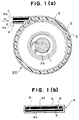
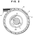
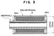
- Figs. 1, 2 and 3 are cross-sectional views showing parts of cartridges and films contained therein according to the present invention.
- the photographic film can be sent out from the cartridge by rotating the spool round which the film is wound in a direction opposite to the film-winding direction.
- the free space in the cartridge must be limited to a certain degree. When the free space is large, the film is reversed to make it impossible that the end of the film is sent out from the cartridge by the rotation of the spool.
- A represents the cross-sectional area of the film roll and B represents the cross-sectional area of the inside of the cartridge.
- the unit is, for example, mm.
- the size is determined at a temperature of 25 °C and at a relative humidity of 55 %.
- the film length is from an end to the other end of the film. When the end of the film is not straight, the most projected part of the end is deemed to be the end. When an end of the film is inserted into the spool, a portion of the film at the slit of the spool is deemed to be the end thereof.
- the thickness of the film is the total of the layers including the film support and gelatin layers containing an emulsion, which is determined by measuring the thickness of the film at ten arbitrary points thereof with a contact film thickness meter (Electronic Micrometer manufactured by Anritsu Electric Co., Ltd.) and taking an average.
- a contact film thickness meter Electric Micrometer manufactured by Anritsu Electric Co., Ltd.
- the cross-sectional area of the spool is that of a part of the spool round which the film is to be wound.
- the cross-sectional area of the cartridge body is the area of the inside of the cartridge not at the upper or lower end thereof but at a part round which the film is to be wound.
- the cartridge has a rib formed inside thereof in order to adjust the position of the film or to smooth the sending of the film, the cross-sectional area of the inside of the rib of a cartridge is employed.
- the cartridge has a flange for controlling the film roll, the cross-sectional area of the inside the flange which adjusts the outermost periphery of the film is employed.
- the void volume V is 0 ⁇ V ⁇ 0.25, preferably 0.04 ⁇ V ⁇ 0.22 and more preferably 0.08 ⁇ V ⁇ 0.18.
- FIGs. 1 (a) and (b) show an example of the cartridge of the present invention.
- a photographic film cartridge 20 comprises a spool 1, a photographic film 2 wound round the spool 1 with an end thereof engaged with the spool 1 and a cartridge body 3.
- the spool 1 is placed in the cartridge body 3 so that it is axially rotatable.
- the spool 1 can be rotated from outside the cartridge body 3.
- the cartridge body 3 has an outlet 4 for drawing out the photographic film 2.
- Light-screening components 4a for keeping the inside of the cartridge body 3 from light is provided in the outlet 4.
- a pair of ribs 8 having a width of about 15 to 20 % based on the film width and extending along the circumference on the inner surface of the cartridge body 3 are provided at positions corresponding to both ends of the width of the film 2.
- the ribs 8 open toward the outlet 4 so that the photographic film 2 can be drawn through it.
- An end 6 of the film 2 is positioned at an end 7 of the film-outlet 4.
- the ribs 8 kept in contact with the outermost surface of the roll of the film 2 keeps the film 2 tightly wound round the spool 1 by pressing it.
- cross-sectional area of cartridge body is the area of the inside of the rib 8.
- the outer diameter of the spool 1 is determined as follows: it is difficult, as described above, to tightly wind the film 2 round the spool 1 while the innermost surface 2a of the film is brought into contact with the outer periphery of the spool 1. It is unavoidable, therefore, that a gap is formed between the innermost surface 2a of the film and the spool 1 in this case. To avoid the formation of the gap, the void volume V must be reduced to 0.25 or less. Further, when the distance h between the innermost surface of the film 2a and the spool 1 is too long, the film 2 turns reversely as shown in Fig. 2.
- the outer diameter of the spool 1 is preferably such that when the gap is formed between the innermost surface 2a of the film and the spool 1, the distance h between them will be 2 mm or less.
- the spool rotation torque is set at 0.8 kgf ⁇ cm or less by controlling the distance h at 2 mm or less, the reverse turn of the photographic film 2 can be prevented.
- the ribs 8 may be formed along the whole peripheral length of the inner surface of the cartridge body 3 but they may be formed along only a part of the peripheral length of the cartridge body 3. Further, the ribs 8 may be formed only at positions corresponding to both ends of the width of the film 2 as in this embodiment or they may be formed also along the whole width of the film 2.
- the material for the ribs 8 is selected from those which do not hurt the film 2 such as plastics.
- the material may be selected from those having some elasticity such as urethane.
- the method of keeping the film-outlet from light is not particularly limited.
- a light-shading felt component called 'teremp' used heretofore can be used.
- the film-outlet is formed so that it can be closed when the film is not drawn through it.
- the end 6 of the film 2 is not necessarily trued up at the end 7 of the film-outlet 4 and it is enough that the end 6 of the film 2 is in the patrone body 3. preferably, however, the end 6 of the film 2 is in the film-outlet 4.
- the shape of the spool flange is modified as described in Japanese Patent Application No. hei 1-172594 so that the film is delivered by rotating the spool while the edge faces of the outermost part of the film roll are pressed.
- ribs opposing to each other are formed on a pair of flanges capable of rotating relatively to the spool shaft to hold the both sides of the film roll in order to prevent the roll from loosening and the shape of the ribs is modified at the film-delivering portion so as to deliver the film by rotating the spool as described in U.S. Patent No. 4,834,306.
- the cross-sectional area of the cartridge body is the cross-sectional area thereof inside of the separation claw.
- the package of the present invention is usually stored in a sealed vessel.
- the sealed vessel may be any of those capable of keeping the photosensitive material contained therein from the outer world.
- the term 'separation' indicates that air in the outer world is substantially separated from air in the vessel.
- Such vessels include, for example, those with a lid which are prepared with a resin having a low vapor permeability such as polyethylene, polypropylene or polyvinyl chloride. They can be rectangular parallelepiped or cylindrical as an ordinary P case.
- the cartridge per se can be sealed so as not to use the P case, while the conventional patrone per se has no sealing properties.
- the sealing of the cartridge per se is not always necessary and the cartridge can be vacuum-sealed in a moisture-proof film such as a polyethylene film, polypropylene film or polyvinyl chloride film.
- the photographic film in the film cartridge of the present invention comprises a transparent support and at least one photosensitive silver halide emulsion layer formed on the support.
- the material of the support is not particularly limited. It is, for example, a cellulose triacetate film, polyester film or the like. To make the package small, the thickness of the support is preferably not more than 125 ⁇ m, more preferably 85 to 115 ⁇ m.
- the photographic film comprises a hydrophilic colloid layer including at least one silver halide emulsion layer formed on the support.
- the thickness of the hydrophilic colloid layer at 25 ° C at a humidity of 55 % under pressure of 1 atm is preferably in the range of 5 to 22 ⁇ m , more preferably 8 to 18 ⁇ m.
- the photographic properties of the packed photographic film are deteriorated with time and particularly, the fogging is accelerated.
- various compounds can be incorporated into the hydrophilic colloid layer in order to stabilize the photographic properties.
- R 11 , R 12 , R 13 and R 14 may be the same or different from one another and they each represent a hydrogen atom, substituted or unsubstituted alkyl group, substituted or unsubstituted aryl group, substituted or unsubstituted amino group, hydroxyl group, alkoxyl group, alkylthio group, substituted or unsubstituted carbamoyl group, halogen atom, cyano group, carboxyl group, alkoxycarbonyl group or heterocyclic residue, R 11 and R 12 or R 12 and R 13 may form together a five-membered or six-membered ring, with the proviso that at least one of R 11 and R 13 represents a hydroxyl group; nitroindazoles triazoles, benzotriazoles, benzimidazoles, benzotriazole compounds of the following general formula: wherein X and Y each represent a
- FI used in the present invention is presented by the following general formula (I) wherein R 21 represents an aliphatic, aromatic or heterocyclic group substituted with at least one -COOM or -SO 3 M, M being a hydrogen atom, alkali metal atom, quaternary ammonium or quaternary phosphonium.
- aliphatic groups herein indicates alkyl groups, alkenyl groups and alkynyl groups.
- the aromatic groups include, for example, phenyl group and naphthyl group.
- the heterocyclic groups include 3- to 8-membered, preferably 5- or 6-membered heterocyclic group having at least one hetero atom selected from among O, N, S and Se and at least one carbon atom.
- R 21 in the above general formula [I] is preferably a phenyl group substituted with at least one COOM or -SO 3 M.
- alkali metals in the above general formula [I] include sodium, potassium and lithium.
- quaternary ammoniums include -NH 4 , -N(CH 3 ) 4 and -N(C 2 H 5 ) 4 .
- R 21 is represented by the formula: wherein X is preferably COOM.
- X in the above general formula [I] represents a sulfo group, carboxyl group or a salt thereof, or a group selected from the group consisting of halogen atoms (such as fluorine, chlorine and bromine atoms), alkyl groups (such as methyl, ethyl, hydroxyethyl, benzyl and ⁇ -dimethylaminoethyl groups), aryl groups (such as phenyl group), alkoxyl groups (such as methoxyl and ethoxyl groups), aryloxy groups (such as phenyloxy group), alkoxycarbonyl groups (such as methoxycarbonyl group), acylamino groups (such as acetylamino and methoxymethylcarbonylamino groups), carbamoyl group, alkylcarbamoyl groups (such as methylcarbamoyl and ethylcarbamoyl groups), dialkylcarbamoyl groups (such as
- X is preferably -SO 3 M, -COOM, an alkyl group having 3 or less carbon atoms, substituted alkyl group, alkoxyl group or substituted alkoxyl group.
- m is preferably 1 or 2.
- the FI compounds may be user either alone or in the form of a mixture of two or more of them in the present invention.
- the FI compound is used in an amount of preferably 10 -6 to 10 -1 , more preferably 10 -5 to 10 -2 mol per 1 mol of silver halide.
- the FI compound is usually dissolved in water or an alcohol and the solution is added to the silver halide emulsion or coating liquid.
- the FI compound can be incorporated in any of the hydrophilic colloid layer, it is particularly effective to incorporate it into a hydrophilic colloid layer containing a photosensitive silver halide emulsion.
- Deterioration of photographic properties with time due to a photographically harmful gas can be unexpectedly effectively inhibited by incorporating a compound of the general formula [I] into the hydrophilic colloid layer.
- the film cartridge of the present invention can contain various photographic films including black-and-white and color photographic films.
- the present invention is preferably applicable to the ordinary color negative films.
- the present invention will be, therefore, illustrated with reference to ordinary color negative films.
- the photographic films used in the present invention may comprise at least seven layers including silver halide emulsion layers, i.e. a blue-sensitive layer, green-sensitive layer and red-sensitive layer formed on a support in which these layers are simultaneously coated on the support.
- silver halide emulsion layers i.e. a blue-sensitive layer, green-sensitive layer and red-sensitive layer formed on a support in which these layers are simultaneously coated on the support.
- the arrangement of the unit photosensitive layers is: a red-sensitive layer, a green-sensitive layer and a blue-sensitive layer in this order from the support.
- the order may be reversed or a different sensitive layer may be interposed between two layers having the same sensitivity depending on the purpose.
- a layer structure comprising the ordinary three layers, i.e. blue-sensitive layer, green-sensitive layer and red-sensitive layer, and in addition, one or more color-sensitive layers formed for the purpose of improving the color reproduction is described in J.P. KOKAI Nos. 61-34541, 61-201245, 61-198236 and 62-160448.
- the position of the fourth color-sensitive layer and other color-sensitive photosensitive layers are not limted.
- the fourth or another color-sensitive photosensitive layer may comprise a single layer or multiple layers.
- a photoinsensitive layer such as an intermediate layer can be provided between the silver halide photosensitive layers or as the top layer or the bottom layer.
- the intermediate layer may contain a coupler or DIR compound as described in J.P. KOKAI Nos. 61-43748, 59-113438, 59-113440, 61-20037 and 61-20038, or an ordinary color-mixing inhibitor.
- the two or more silver halide emulsion layers constituting the unit photosensitive layer have preferably a structure consisting of two layers, i.e. a high-sensitivity emulsion layer and a low-sensitivity emulsion layer, as described in West German Patent No. 1,121,470 or British Patent No. 923,045.
- the arrangement of the layers be such that the sensitivity thereof decreases gradually toward the support.
- a photoinsensitive layer may be provided between the silver halide emulsion layers.
- An emulsion layer having a low sensitivity may be formed away from the support and an emulsion layer having a high sensitivity may be formed close to the support as described in J.P. KOKAI No. 57-112751, 62-200350, 62-206541 and 62-206543.
- An example of the arrangement is a structure of a blue-sensitive layer having a low sensitivity (BL)/blue-sensitive layer having a high sensitivity (BH)/green-sensitive layer having a high sensitivity (GH)/green-sensitive layer having a low sensitivity (GL)/red-sensitive layer having a high sensitivity (RH)/red-sensitive layer having a low sensitivity (RL); BH/BL/GL/GH/RH/RL or BH/BL/GH/GL/RL/RH toward the support.
- BL low sensitivity
- BH high sensitivity
- GH high sensitivity
- GL low sensitivity
- RH high sensitivity
- RL high sensitivity
- the arrangement may be a blue-sensitive layer /GH/RH/GL/RL toward the support.
- Another arrangemnet is a blue-sensitive layer/GL/RL/GH/RH toward the support as described in J.P. KOKAI Nos. 56-25738 and 62-63936.
- a sensitive layer may comprise further an emulsion layer having a medium sensitivity / emulsion layer having a high sensitivity / emulsion layer having a low sensitivity in the order toward the support as described in J.P. KOKAI No. 59-202464.
- Still another arrangement is a structure of high-sensitivity emulsion layer / low-sensitivity emulsion layer / medium-sensitivity emulsion layer or low-sensitivity emulsion layer / medium-sensitivity emulsion layer / high-sensitivity emulsion layer.
- the arrangement of the layers may be varied as described above.
- the layer construction and the arrangement can be selected suitably for the use of the photosensitive material.
- the amount of the silver halide used in the present invention is not particularly limited, it is preferably 3 to 10 g/m 2 , more preferably 3 to 7 g/m 2 (in terms of silver).
- the silver density based on the gelatin binder is also not particularly limited, silver is used in such an amount that the weight ratio of silver to gelatin will be in the range of 0.01 to 5.0 depending on the intended sensitivity of the emulsion layer.
- Preferred silver halides contained in the photographic emulsion layers of the photosensitive material used in the present invention include silver bromoiodide, silver chloroiodide and silver chlorobromoiodide, which contain about 30 molar % or less of silver iodide. Particularly preferred is silver bromoiodide or silver chlorobromoiodide containing about 2 to 25 molar % of silver iodide.
- the silver halide grains in the photographic emulsion may be in a regular crystal form such as a cubic, octahedral or tetradecahedral form; an irregular crystal form such as spherical or plate form; those having a crystal fault such as a twin plate; or a complex crystal form thereof.
- the silver halide grain diameter may be not more than about 0.2 ⁇ m or the projection area diameter thereof may be about 10 ⁇ m or less.
- the emulsion may be either a polydisperse emulsion or monodisperse emulsion.
- the silver halide photographic emulsion usable in the present invention can be prepared by processes described in, for example, 'Research Disclosure (RD)' No. 17643 (December, 1978), pages 22 to 23, '1. Emulsion Preparation and types'; RD No. 18716 (November, 1979), p. 648; P. Glafkides, 'Chemic et Phisique Photographique', Paul Montel, 1967; G.F. Duffin, 'Photographic Emulsion Chemistry' (Focal Press, 1966); and V.L. Zelikman et al., 'Making and Coating Photographic Emulsion', (Focal Press, 1964).
- Monodisperse emulsions described in U.S. Patent Nos. 3,574,628 and 3,655,394 and British Patent No. 1,413,748 are also preferred.
- Tabular grains having an aspect ratio of about 5 or higher are also usable.
- the tabular grains can be easily prepared by processes described in, for example, Gutoff, 'Photographic Science and Engineering', Vol. 14, pages 248 to 257 (1970); U.S. Patent Nos. 4,434,226, 4,414,310, 4,433,048 and 4,439,520 and British Patent No. 2,112,157.
- the crystal structure of the grains in the above emulsion may be homogeneous; the grains may comprise an inside portion and an outside portion which are composed of silver halides different from each other; or the structure may be a laminated one. Different silver halide grains can be bonded together by an epitaxial bond or they can be bonded with a compound other than silver halides such as silver rhodanate or lead oxide.
- a mixture of grains having various crystal forms can also be used.
- the silver halide emulsion to be used in the present invention is usually physically and chemically ripened and spectrally sensitized.
- the additives to be used in these steps are shown in Research Disclosure Nos. 17643 and 18716. The portions in which the additives are mentioned in these two Research Disclosure's are summarized in the following table.
- Preferred yellow couplers are those described in, for example, U.S. Patent Nos. 3,933,051, 4,022,620, 4,326,024, 4,401,752 and 4,248,961, J.P. KOKOKU No. 58-10739, British Patent Nos. 1,425,020 and 1,476,760, U.S. Patent Nos. 3,973,968, 4,314,023 and 4,511,649, and European Patent No. 249,473A.
- magenta couplers usable in the present invention are preferably 5-pyrazolone couplers and pyrazoloazole couplers. Particularly preferred are those described in U.S. Patent Nos. 4,310,619 and 4,351,897, European Patent No. 73,636, U.S. Patent Nos. 3,061,432 and 3,725,067, Research Disclosure No. 24220 (June, 1984), J.P. KOKAI No. 60-33552, Research Disclosure No. 24230 (June, 1984), J.P. KOKAI Nos. 60-43659, 61-72238, 60-35730, 55-118034 and 60-185951, U.S. Patent Nos. 4,500,630, 4,540,654 and 4,556,630, and WO (PCT) 88/04795.
- the cyan couplers usable in the present invention are phenolic and naphtholic couplers.
- Preferred cyan couplers are those described in U.S. Patent Nos. 4,052,212, 4,146,396, 4,228,233, 4,296,200, 2,369,929, 2,801,171, 2,772,162, 2,895,826, 3,772,002, 3,758,308, 4,334,011 and 4,327,173, West German Patent Unexamined Published Application No. 3,329,729, European Patent Nos. 121,365A and 249,453A, U.S. Patent Nos. 3,446,622, 4,333,999, 4,775,616, 4,451,559, 4,427,767, 4,690,889, 4,254,212 and 4,296,199 and J.P. KOKAI No. 61-42658.
- Colored couplers used for compensation for unnecessary absorption of the colored dye are preferably those described in Research Disclosure No. 17643, VII-G, U.S. Patent No. 4,163,670, J.P. KOKOKU No. 57-39413, U.S. Patent Nos. 4,004,929 and 4,138,258 and British Patent No. 1,146,368. It is also preferred to use couplers for compensation for unnecessary absorption of the colored dye with a fluorescent dye released in the coupling as described in U. S. Patent No. 4,774,181 or couplers having, as a split-off group, a dye precursor group capable of forming a dye by reaction with a developing agent as described in U.S. Patent No. 4,777,120.
- the couplers capable of forming a color dye having a suitable diffusivity are preferably those described in U.S. Patent No. 4,366,237, British Patent No. 2,125,570, European Patent No. 96,570 and West German Patent No. 3,234,533.
- Typical examples of the polymerized color-forming couplers are described in, for example, U.S. Patent Nos. 3,451,820, 4,080,211, 4,367,282, 4,409,320 and 4,576,910 and British Patent No. 2,102,173.
- couplers which release a photographically useful residual group during a coupling reaction are also preferably usable in the present invention.
- DIR couplers which release a development inhibitor are preferably those described in the patents shown in the above described RD 17643, VII-F as well as J.P. KOKAI No. 57-151944, 57-154234, 60-184248 and 63-37346 and U.S. Patent Nos. 4,248,962 and 4,782,012.
- the couplers which release a nucleating agent or a development accelerator in the image-form are preferably those described in British Patent Nos. 2,097,140 and 2,131,188 and J.P. KOKAI Nos. 59-157638 and 59-170840.
- couplers usable for the photosensitive material of the present invention include competing couplers described in U.S. Patent No. 4,130,427, polyequivalent couplers described in U.S. Patent Nos. 4,283,472, 4,338,393 and 4,310,618, DIR redox compound-releasing couplers, DIR coupler-releasing couplers, DIR coupler-releasing redox compounds and DIR redox-releasing redox compounds described in J.P. KOKAI Nos. 60-185950 and 62-24252, couplers which release a dye that restores the color after coupling-off described in European Patent No. 173,302A, bleach-accelerator-releasing couplers described in R.D. Nos.
- the coupler used in the present invention can be incorporated into the photosensitive material by various known dispersion methods.
- High-boiling solvents used for an oil-in-water dispersion method are described in, for example, U.S. Patent No. 2,322,027.
- the high-boiling organic solvents having a boiling point under atmospheric pressure of at least 175 °C and usable in the oil-in-water dispersion method include, for example, phthalates [such as dibutyl phthalate, dicyclohexyl phthalate, di-2-ethylhexyl phthalate, decyl phthalate, bis(2,4-di-t-amylphenyl) phthalate, bis(2,4-di-t-amylphenyl) isophthalate and bis(1,1-diethylpropyl) phthalate], phosphates and phosphonates [such as triphenyl phosphate, tricresyl phosphate, 2-ethylhexyldiphenyl phosphate, tricyclohexyl phosphate, tri-2-ethylhexyl phosphate, tridecyl phosphate, tributoxyethyl phosphate, trichloropropy
- Co-solvents usable in the present invention include, for example, organic solvents having a boiling point of at least about 30°C, preferably 50 to about 160°C. Typical examples include ethyl acetate, butyl acetate, ethyl propionate, methyl ethyl ketone, cyclohexanone, 2-ethoxyethyl acetate and dimethylformamide.
- the present invention is applicable to various color photosensitive materials such as ordinary color negative films, cinema color negative films, reversal color films for slides or televisions, color papers, positive color films and reversal color papers.
- Suitable supports usable in the present invention are described in, for example, on page 28 of the above-described RD. No. 17643 and from right column, page 647 to left column, page 648 of RD. No. 18716.
- the photographic film used in the present invention has a total thickness of the hydrophilic colloidal layers on the emulsion layer-side of 24 ⁇ m or less, preferably 20 ⁇ m or less and more preferably 18 ⁇ m or less and a film-swelling rate T 1/2 of preferably 30 sec or less, more preferably 20 sec or less.
- the thickness is determined at 25 °C and at a relative humidity of 55% (2 days).
- the film-swelling rate T 1/2 can be determined by a method known in this technical field.
- T 1/2 is defined to be the time required for attaining the thickness if T 1/2 which is the saturated film thickness (corresponding to 90% of the maximum thickness of film swollen with the color developer at 30 °C for 3 min 15 sec.).
- the film-swelling rate T 1/2 can be controlled by adding a hardener to gelatin used as the binder or by varying the time conditions after the coating.
- the swelling rate is preferably 150 to 400%.
- the swelling rate is calculated according to the following formula: [(maximum swollen film thickness) - (film thickness)] / (film thickness) wherein the maximum swollen film thickness is determined under the above-described conditions.
- the color photographic film used in the present invention can be developed by an ordinary method described in, for example, the above-described R.D. No. 17643, pages 28 to 29 and R.D. No. 18716, page 615, left to the right columns.
- J.UM. KOKAI Japanese Utility Model Unexamined Published Application
- J.P. KOKAI Nos. 58-181035 and 58-182634 J.UM. KOKAI No. 58-195236
- U.S. Patent No. 4,221,479 Japanese Patent Application Nos.
- a multi-layered color photographic film composed of layers of the following compositions formed on a primed cellulose triacetate film support having a thickness of 120 ⁇ m was prepared.
- the numerals for the components each show the amount of the coating (g/m 2 ).
- the amounts of the silver halides are given in terms of silver applied.
- the amount of the sensitizing dye is shown in terms of the molar number thereof per mol of the silver halide contained in the same layer.
- the first layer (antihalation layer):
- the second layer (intermediate layer):
- the third layer (the first red-sensitive emulsion layer)
- the fourth layer (the second red-sensitive emulsion layer)
- Emulsion G silver 1.00 Sensitizing Dye I 5.1 x 10 -5 Sensitizing Dye II 1.4 x 10 -5 Sensitizing Dye III 2.3 x 10 -4 EX-2 0.40 EX-3 0.050 EX-10 0.015 U-1 0.070 U-2 0.050 U-3 0.070 gelatin 1.30
- the fifth layer (the third red-sensitive emulsion layer)
- Emulsion D silver 1.60 Sensitizing Dye I 5.4 x 10 -5 Sensitizing Dye II 1.4 x 10 -5 Sensitizing Dye III 2.4 x 10 -4 EX-2 0.097 EX-3 0.010 EX-4 0.080 HBS-1 0.22 HBS-2 0.10 gelatin 1.63
- the sixth layer (intermediate layer)
- the seventh layer (the first green-sensitive emulsion layer)
- the eighth layer (the second green-sensitive emulsion layer)
- Emulsion C silver 0.45 Sensitizing Dye IV 2.1 x 10 -5 Sensitizing Dye V 7.0 x 10 -5 Sensitizing Dye VI 2.6 x 10 -4 EX-6 0.094 EX-7 0.026 EX-8 0.018 HBS-1 0.16 HBS-3 8.0 x 10 -3 gelatin 0.50
- the ninth layer (the third green-sensitive emulsion layer)
- the tenth layer (yellow filter layer)
- the eleventh layer (the first blue-sensitive emulsion layer)
- Emulsion A silver 0.080 Emulsion B
- silver 0.070 Emulsion F silver 0.070 Sensitizing Dye VII 3.5 x 10 -4
- EX-8 0.042
- EX-9 0.72 HBS-1 0.28 gelatin 1.10
- the twelfth layer (the second blue-sensitive emulsion layer)
- Emulsion G silver 0.45 Sensitizing Dye VII 2.1 x 10 -4 EX-9 0.15 EX-10 7.0 x 10 -3 HBS-1 0.050 gelatin 0.78
- the thirteenth layer (the third blue-sensitive emulsion layer)
- the fourteenth layer (the first protective layer)
- Emulsion I silver 0.20 U-4 0.11 U-5 0.17 HBS-1 5.0 x 10 -2 gelatin 1.00
- the fifteenth layer (the second protective layer)
- W-1, W-2, W-3, B-4, B-5 and F-1 as well as an iron salt, lead salt, gold salt, platinum salt, iridium salt and rhodium salt were incorporated into all the layers in order to prevent the processability, pressure resistance, mildew resistance, antimicrobial properties, antistatic properties and spreadability.
- Samples 102 to 109 were prepared in the same manner as that of the preparation of Sample 101 except that the variety and amount of the fog inhibitor were altered as shown in Table 2.
- the thickness of the hydrophilic colloid layer of Samples 101 to 109 was 21.0 ⁇ m.
- Samples 101 to 109 were left to stand at 25 °C at a relative humidity of 65 % for one week and then cut to form slits having a width of 35 mm under the same temperature and humidity conditions as above.
- the slits were cut to a length of 130 cm and each slit was rolled in a cartridge shown in Fig. 3 to form Samples A-101 to A-109, respectively.
- Samples B-101 to B-109 were prepared in the same manner as described above except that the length of the films in Samples A-101 to A-109 were altered to 145 cm.
- Samples C-101 to C-109 were prepared in the same manner as described above except that the length of the films were altered to 150 cm.
- Samples D-101 to D-109 having the film length of 160 cm were prepared in the same manner as above. Although it was tried to roll longer films, the friction in the cartridge was increased to also increase the sending stress.
- Samples A-101 to 109 and D-101 to 109 were kept at 60 °C for 3 days or at room temperature. They were subjected to sensitometric exposure (4800 ° K, 1/100 sec, 2CMS) and then to color development by process A.
- the preparation of a film cartridge containing a photographic film with a small cartridge which is capable of surely sending out the film is made possible.
- Process A Step Time Temp. Amount of replenisher Capacity of tank Color development 3 min 15 sec 38 °C 33 ml 20 l Bleaching 6 min 30 sec 38 °C 25 ml 40 l Washing with water 2 min 10 sec 24 °C 1200 ml 20 l Fixing 4 min 20 sec 38 °C 25 ml 30 l Washing with water (1) 1 min 05 sec 24 °C counter-current from (2) to (1) 10 l Washing with water (2) 1 min 00 sec 24 °C 1200 ml 10 l Stabilization 1 min 05 sec 38 °C 25 ml 10 l Drying 4 min 20 sec 55 °C
- the amount of replenisher is given per width of 35 mm and length of 1 m.
- compositions of the processing solutions were as follows:
- Amount of replenisher Capacity of tank Color development 3 min 15 sec 38 °C 45 ml 10 l Bleaching 1 min 00 sec 38 °C 20 ml 4 l Bleach-fixing 3 min 15 sec 38 °C 30 ml 8 l Washing with water (1) 40 sec 35 °C Countercurrent° from (2) to (1) 4 l Washing with water (2) 1 min 00 sec 35 °C 30 ml 4 l Stabilization 40 sec 38 °C 20 ml 4 l Drying 1 min 15 sec 55 °C
- the amount of replenisher is given per width of 35 mm and length of 1 m.
- compositions of the processing solutions were as follows:
- Ferric ammonium ethylenediaminetetraacetate dihydrate 50.0 Disodium ethylenediaminetetraacetate 5.0 Sodium sulfite 12.0
- Aqueous ammonium thiosulfate solution (70 %) 240.0 ml
- Aqueous ammonia (27 %) 6.0 ml
Landscapes
- Physics & Mathematics (AREA)
- Engineering & Computer Science (AREA)
- General Physics & Mathematics (AREA)
- Chemical & Material Sciences (AREA)
- Microelectronics & Electronic Packaging (AREA)
- Spectroscopy & Molecular Physics (AREA)
- Chemical Kinetics & Catalysis (AREA)
- Materials Engineering (AREA)
- Silver Salt Photography Or Processing Solution Therefor (AREA)
Description
- The present invention relates to a film cartridge containing a photographic film. In particular, the present invention relates to a small film cartridge containing a photographic film capable of facilitating charging of a camera with a photographic film. The photographic properties of a photographic film comprising a silver halide in the film cartridge of the present invention can be protected from deterioration during storage before the use.
- In a conventional photographic film patrone, the film is wound round a spool not tightly but loosely and, therefore, the film cannot be sent toward the outside by rotating the spool in a direction opposite to the winding direction. Accordingly, it has been necessary to previously draw out a proper length of an end of the photographic film from the patrone so that the user can hook the end of the film in a film-feeding mechanism of a camera.
- However, this operation takes time and since it requires some amount of skill, the camera is sometimes not correctly charged with the film. In such a case, the photographing is conducted while the film is not advanced.
- Under these conditions, the developement of a camera which does not necessitate such an operation has been demanded.
- Such a camera can be produced if the photographic film can be sent out from the cartridge. Namely, if the photographic film can be sent out from the cartridge, the film can be engaged with a film-advancing mechanism in the camera by sending out the end of the film to make the operation of hooking the end of the film in the film-advancing mechanism of the camera unnecessary. It is necessitated, therefore, to develope a cartridge capable of sending out the film therefrom in place of the ordinary patrone.
- It is considered that the photographic film can be sent out from the cartridge by a method comprising rotating the spool in a direction opposite to the film-winding direction. In this method, the free space in the cartridge must be limited to below a certain degree, since when the free space is large, the film is reversed to make it impossible that the end of the film is sent out from the cartridge by the rotation of the spool.
- However, on the other hand, when the free space is reduced too much, a new problem is posed that when the film cartridge containing the photographic film is stored particularly at a high temperature, deterioration of the photographic properties of the photographic film is accelerated and, particularly, fog of the photographic film is increased with time. Thus the cartridge which can be easily set in a camera could not be produced.
- U.S. Patent No. 4,887,776 discloses a film cassette wherein a spool includes two coaxial core pieces having a convoluted film roll coiled about them, whose outermost convolution is a film leader, and respective flanges fixed to the core pieces which radially extend over the opposite sides of the film roll. At least one of the core pieces is supported for movement axially toward the other one to move at least one of the flanges axially toward the other one to provide axial clamping forces at the opposite sides of the film roll. A film stripper-guide is received between the outermost convolution and the nextinward convolution of the film roll to strip the outermost convolution from the flanges and guide it through a film passageway to the exterior of the cassette shell responsive to rotation of the spool in a film unwinding direction during application of the axial clamping forces. According to this document, at least one of the flanges includes integral means for concentrating the axial clamping forces substantially at the outermost convolution of the film roll and preventing application of the axial clamping forces substantially at the more-inward convolutions of the film roll.
- After intensive investigations, the inventors have found that the deterioration of the photographic properties caused when the free space in the cartridge is small is caused because the amount of water formed from the photographic film and the concentration of a gas harmful to the photographic properties are increased. No process has been proposed heretofore for effectively preventing deterioration of the photographic properties due to the harmful gas.
- An object of the present invention is to provide a small film cartridge of photographic film which can be easily and surely installed in a camera and which has improved photographic properties resistant to deterioration with time.
- The object of the present invention is attained by a film cartridge containing a photographic film, which comprises a spool, a photographic film engaged with the spool at an end and rolled round the spool and a cartridge body, the whole photographic film being placed in the cartridge, wherein the void volume V in the cartridge which is represented by the following formula is not higher than 0.25, the photographic film comprises at least one photosensitive silver halide emulsion layer formed on a transparent support and the photographic film contains a compound of the following general formulae [I],

- A = (cross-sectional area of the rolled film)
= (thickness of film) x (length of film) - B = (cross-sectional area of inside of cartridge)
= (cross-sectional area of cartridge body) - (cross-sectional area of spool);
- Figs. 1, 2 and 3 are cross-sectional views showing parts of cartridges and films contained therein according to the present invention.
- 1 and 35 . . . . . spool,
- 2 . . . . . film,
- 3,35 . . . . . cartridge.
- In the film cartridge of the present invention, it is considered that the photographic film can be sent out from the cartridge by rotating the spool round which the film is wound in a direction opposite to the film-winding direction. In this method, the free space in the cartridge must be limited to a certain degree. When the free space is large, the film is reversed to make it impossible that the end of the film is sent out from the cartridge by the rotation of the spool.
- The film cannot be stably sent out unless the void volume of the cartridge as represented by the above formula is 0.25 or less. In the formula, A represents the cross-sectional area of the film roll and B represents the cross-sectional area of the inside of the cartridge. They are defined as follows:
- A = (thickness of film) x (length of film)
- B = (cross-sectional area of cartridge body) - (cross-sectional area of spool);
- The unit is, for example, mm. The size is determined at a temperature of 25 °C and at a relative humidity of 55 %.
- The film length is from an end to the other end of the film. When the end of the film is not straight, the most projected part of the end is deemed to be the end. When an end of the film is inserted into the spool, a portion of the film at the slit of the spool is deemed to be the end thereof.
- The thickness of the film is the total of the layers including the film support and gelatin layers containing an emulsion, which is determined by measuring the thickness of the film at ten arbitrary points thereof with a contact film thickness meter (Electronic Micrometer manufactured by Anritsu Electric Co., Ltd.) and taking an average.
- The cross-sectional area of the spool is that of a part of the spool round which the film is to be wound.
- The cross-sectional area of the cartridge body is the area of the inside of the cartridge not at the upper or lower end thereof but at a part round which the film is to be wound. When the cartridge has a rib formed inside thereof in order to adjust the position of the film or to smooth the sending of the film, the cross-sectional area of the inside of the rib of a cartridge is employed. When the cartridge has a flange for controlling the film roll, the cross-sectional area of the inside the flange which adjusts the outermost periphery of the film is employed.
- The void volume V is 0<V≦0.25, preferably 0.04 ≦V ≦ 0.22 and more preferably 0.08 ≦ V ≦ 0.18.
- Figs. 1 (a) and (b) show an example of the cartridge of the present invention. A
photographic film cartridge 20 comprises a spool 1, aphotographic film 2 wound round the spool 1 with an end thereof engaged with the spool 1 and acartridge body 3. The spool 1 is placed in thecartridge body 3 so that it is axially rotatable. The spool 1 can be rotated from outside thecartridge body 3. Thecartridge body 3 has anoutlet 4 for drawing out thephotographic film 2. Light-screening components 4a for keeping the inside of thecartridge body 3 from light is provided in theoutlet 4. - In the
photographic film cartridge 20 of this embodiment, a pair ofribs 8 having a width of about 15 to 20 % based on the film width and extending along the circumference on the inner surface of thecartridge body 3 are provided at positions corresponding to both ends of the width of thefilm 2. Theribs 8 open toward theoutlet 4 so that thephotographic film 2 can be drawn through it. Anend 6 of thefilm 2 is positioned at an end 7 of the film-outlet 4. - The
ribs 8 kept in contact with the outermost surface of the roll of thefilm 2 keeps thefilm 2 tightly wound round the spool 1 by pressing it. - In this case, the term "cross-sectional area of cartridge body" is the area of the inside of the
rib 8. - The outer diameter of the spool 1 is determined as follows: it is difficult, as described above, to tightly wind the
film 2 round the spool 1 while theinnermost surface 2a of the film is brought into contact with the outer periphery of the spool 1. It is unavoidable, therefore, that a gap is formed between theinnermost surface 2a of the film and the spool 1 in this case. To avoid the formation of the gap, the void volume V must be reduced to 0.25 or less. Further, when the distance h between the innermost surface of thefilm 2a and the spool 1 is too long, thefilm 2 turns reversely as shown in Fig. 2. Therefore, the outer diameter of the spool 1 is preferably such that when the gap is formed between theinnermost surface 2a of the film and the spool 1, the distance h between them will be 2 mm or less. The relationship between them can be formulated as follows:

- Since the distance h is represented by the following formula:


- When the spool rotation torque is set at 0.8 kgf· cm or less by controlling the distance h at 2 mm or less, the reverse turn of the
photographic film 2 can be prevented. - It is unnecessary to form the
ribs 8 along the whole peripheral length of the inner surface of thecartridge body 3 but they may be formed along only a part of the peripheral length of thecartridge body 3. Further, theribs 8 may be formed only at positions corresponding to both ends of the width of thefilm 2 as in this embodiment or they may be formed also along the whole width of thefilm 2. - The material for the
ribs 8 is selected from those which do not hurt thefilm 2 such as plastics. The material may be selected from those having some elasticity such as urethane. when the thickness of theurethane ribs 8 is determined so that they will be shrunk when thefilm 2 wound round the spool 1 is placed in thecartridge body 3, the outermost surface of thefilm roll 2 is pressed by rebound of the shrunkribs 8 and, therefore, even after a considerable length of thefilm 2 has been drawn out to make the outer diameter of the roll smaller, the film roll can be kept tight. The cross-sectional area of the cartridge body is the cross-sectional area of the inside of the ribs prior to the sending-out of the film in this case. - In all of the above embodiments, the method of keeping the film-outlet from light is not particularly limited. A light-shading felt component called 'teremp' used heretofore can be used. Alternatively, the film-outlet is formed so that it can be closed when the film is not drawn through it. The
end 6 of thefilm 2 is not necessarily trued up at the end 7 of the film-outlet 4 and it is enough that theend 6 of thefilm 2 is in thepatrone body 3. preferably, however, theend 6 of thefilm 2 is in the film-outlet 4. - In another preferred embodiment of the cartridge, the shape of the spool flange is modified as described in Japanese Patent Application No. hei 1-172594 so that the film is delivered by rotating the spool while the edge faces of the outermost part of the film roll are pressed.
- In still another preferred embodiment of the cartridge, ribs opposing to each other are formed on a pair of flanges capable of rotating relatively to the spool shaft to hold the both sides of the film roll in order to prevent the roll from loosening and the shape of the ribs is modified at the film-delivering portion so as to deliver the film by rotating the spool as described in U.S. Patent No. 4,834,306. In this case, the cross-sectional area of the cartridge body is the cross-sectional area thereof inside of the separation claw.
- A further preferred embodiments of the cartridgte are described in U.S. Patent Nos. 4,846,418 and 4,832,275.
- The package of the present invention is usually stored in a sealed vessel.
- The sealed vessel may be any of those capable of keeping the photosensitive material contained therein from the outer world. The term 'separation' indicates that air in the outer world is substantially separated from air in the vessel. Thus any vessel satisfying the above-described conditions can be used as the sealed vessel irrespective of the material or shape thereof. Such vessels include, for example, those with a lid which are prepared with a resin having a low vapor permeability such as polyethylene, polypropylene or polyvinyl chloride. They can be rectangular parallelepiped or cylindrical as an ordinary P case. In addition, the cartridge per se can be sealed so as not to use the P case, while the conventional patrone per se has no sealing properties. In the present invention wherein the end of the photographic material (film ) has not been drawn through the film-outlet of the cartridge but kept in the cartridge, the sealing of the cartridge per se is not always necessary and the cartridge can be vacuum-sealed in a moisture-proof film such as a polyethylene film, polypropylene film or polyvinyl chloride film.
- The photographic film in the film cartridge of the present invention comprises a transparent support and at least one photosensitive silver halide emulsion layer formed on the support.
- The material of the support is not particularly limited. It is, for example, a cellulose triacetate film, polyester film or the like. To make the package small, the thickness of the support is preferably not more than 125 µm, more preferably 85 to 115 µm.
- The photographic film comprises a hydrophilic colloid layer including at least one silver halide emulsion layer formed on the support. The thickness of the hydrophilic colloid layer at 25 ° C at a humidity of 55 % under pressure of 1 atm is preferably in the range of 5 to 22 µm , more preferably 8 to 18 µm.
- As described above, when the void volume in the cartridge is reduced, the photographic properties of the packed photographic film are deteriorated with time and particularly, the fogging is accelerated. Usually, various compounds can be incorporated into the hydrophilic colloid layer in order to stabilize the photographic properties.
- These compounds include tetrazaindene compounds of the following general formula:


mercapto compounds; quaternary salt compounds; and thion compounds. - However, with these compounds, it is impossible to sufficiently improve the storability which has been deteriorated by reducing the void volume in the cartridge. Thus the film cartridge as intended in the present invention could not be obtained in the prior art. It has been found that the incorporation of at least one of specified fog inhibitors (FI) described in Japanese Patent Unexamined Published Application (hereinafter referred to as "J.P. KOKAI") No. 60-153039 into the hydrophilic colloid layer of the photographic film in the film cartridge of the present invention is particularly effective for attaining the object of the present invention. Now, the description will be made on the fog inhibitors.
- The FI used in the present invention is presented by the following general formula (I)

- The term "aliphatic groups" herein indicates alkyl groups, alkenyl groups and alkynyl groups. The aromatic groups include, for example, phenyl group and naphthyl group. The heterocyclic groups include 3- to 8-membered, preferably 5- or 6-membered heterocyclic group having at least one hetero atom selected from among O, N, S and Se and at least one carbon atom.
- R21 in the above general formula [I] is preferably a phenyl group substituted with at least one COOM or -SO3M.
- Examples of the alkali metals in the above general formula [I] include sodium, potassium and lithium. Examples of the quaternary ammoniums include -NH4, -N(CH3)4 and -N(C2H5)4.
- R21 is represented by the formula:

- X in the above general formula [I] represents a sulfo group, carboxyl group or a salt thereof, or a group selected from the group consisting of halogen atoms (such as fluorine, chlorine and bromine atoms), alkyl groups (such as methyl, ethyl, hydroxyethyl, benzyl and β-dimethylaminoethyl groups), aryl groups (such as phenyl group), alkoxyl groups (such as methoxyl and ethoxyl groups), aryloxy groups (such as phenyloxy group), alkoxycarbonyl groups (such as methoxycarbonyl group), acylamino groups (such as acetylamino and methoxymethylcarbonylamino groups), carbamoyl group, alkylcarbamoyl groups (such as methylcarbamoyl and ethylcarbamoyl groups), dialkylcarbamoyl groups (such as dimethylcarbamoyl group), arylcarbamoyl groups (such as phenylcarbamoyl group), alkylsulfonyl groups (such as methylsulfonyl group), arylsulfonyl groups (such as phenylsulfonyl group), alkylsulfonamido groups (such as methanesulfonamido group), arylsulfonamido groups (such as phenylsulfonamido group), sulfamoyl group, alkylsulfamoyl groups (such as ethylsulfamoyl group), dalylsulfamoyl groups (such as dimethylsulfamoyl group), alkylthio groups (such as methylthio group), arylthio groups (such as phenylthio group), cyano group, nitro group, hydroxyl group and amino group. When the compound has two substituents, they may be the same or different from each other.
- X is preferably -SO3M, -COOM, an alkyl group having 3 or less carbon atoms, substituted alkyl group, alkoxyl group or substituted alkoxyl group.
- m is preferably 1 or 2.
- Examples of these compounds are as follows:


- The FI compounds may be user either alone or in the form of a mixture of two or more of them in the present invention. The FI compound is used in an amount of preferably 10-6 to 10-1, more preferably 10-5 to 10-2 mol per 1 mol of silver halide.
- The FI compound is usually dissolved in water or an alcohol and the solution is added to the silver halide emulsion or coating liquid.
- Although the FI compound can be incorporated in any of the hydrophilic colloid layer, it is particularly effective to incorporate it into a hydrophilic colloid layer containing a photosensitive silver halide emulsion.
- Deterioration of photographic properties with time due to a photographically harmful gas, the amount of which is increased as the void in the cartridge is reduced, can be unexpectedly effectively inhibited by incorporating a compound of the general formula [I] into the hydrophilic colloid layer.
- The film cartridge of the present invention can contain various photographic films including black-and-white and color photographic films. The present invention is preferably applicable to the ordinary color negative films. The present invention will be, therefore, illustrated with reference to ordinary color negative films.
- The photographic films used in the present invention may comprise at least seven layers including silver halide emulsion layers, i.e. a blue-sensitive layer, green-sensitive layer and red-sensitive layer formed on a support in which these layers are simultaneously coated on the support.
- In the multi-layered silver halide color photosensitive materials, the arrangement of the unit photosensitive layers is: a red-sensitive layer, a green-sensitive layer and a blue-sensitive layer in this order from the support. However, the order may be reversed or a different sensitive layer may be interposed between two layers having the same sensitivity depending on the purpose.
- A layer structure comprising the ordinary three layers, i.e. blue-sensitive layer, green-sensitive layer and red-sensitive layer, and in addition, one or more color-sensitive layers formed for the purpose of improving the color reproduction is described in J.P. KOKAI Nos. 61-34541, 61-201245, 61-198236 and 62-160448. In this case, the position of the fourth color-sensitive layer and other color-sensitive photosensitive layers are not limted. The fourth or another color-sensitive photosensitive layer may comprise a single layer or multiple layers.
- A photoinsensitive layer such as an intermediate layer can be provided between the silver halide photosensitive layers or as the top layer or the bottom layer.
- The intermediate layer may contain a coupler or DIR compound as described in J.P. KOKAI Nos. 61-43748, 59-113438, 59-113440, 61-20037 and 61-20038, or an ordinary color-mixing inhibitor.
- The two or more silver halide emulsion layers constituting the unit photosensitive layer have preferably a structure consisting of two layers, i.e. a high-sensitivity emulsion layer and a low-sensitivity emulsion layer, as described in West German Patent No. 1,121,470 or British Patent No. 923,045. Usually, it is peferable that the arrangement of the layers be such that the sensitivity thereof decreases gradually toward the support. A photoinsensitive layer may be provided between the silver halide emulsion layers. An emulsion layer having a low sensitivity may be formed away from the support and an emulsion layer having a high sensitivity may be formed close to the support as described in J.P. KOKAI No. 57-112751, 62-200350, 62-206541 and 62-206543.
- An example of the arrangement is a structure of a blue-sensitive layer having a low sensitivity (BL)/blue-sensitive layer having a high sensitivity (BH)/green-sensitive layer having a high sensitivity (GH)/green-sensitive layer having a low sensitivity (GL)/red-sensitive layer having a high sensitivity (RH)/red-sensitive layer having a low sensitivity (RL); BH/BL/GL/GH/RH/RL or BH/BL/GH/GL/RL/RH toward the support.
- As described in J.P. KOKOKU No. 55-34932, the arrangement may be a blue-sensitive layer /GH/RH/GL/RL toward the support. Another arrangemnet is a blue-sensitive layer/GL/RL/GH/RH toward the support as described in J.P. KOKAI Nos. 56-25738 and 62-63936.
- Another arrangement is that of three layers having sensitivities gradually lowered toward the support, i.e. a top layer (a silver halide emulsion layer having the highest sensitivity), middle layer (a silver halide emulsion layer having a lower sensitivity) and bottom layer (a silver halide emulsion layer having a sensitivity lower than that of the middle layer) as described in J.P. KOKOKU No. 49-15495. Even in such an arrangement, a sensitive layer may comprise further an emulsion layer having a medium sensitivity / emulsion layer having a high sensitivity / emulsion layer having a low sensitivity in the order toward the support as described in J.P. KOKAI No. 59-202464.
- Still another arrangement is a structure of high-sensitivity emulsion layer / low-sensitivity emulsion layer / medium-sensitivity emulsion layer or low-sensitivity emulsion layer / medium-sensitivity emulsion layer / high-sensitivity emulsion layer.
- When the photosensitive material comprises four or more layers, the arrangement of the layers may be varied as described above.
- Thus the layer construction and the arrangement can be selected suitably for the use of the photosensitive material.
- Although the amount of the silver halide used in the present invention is not particularly limited, it is preferably 3 to 10 g/m2, more preferably 3 to 7 g/m2 (in terms of silver).
- Although the silver density based on the gelatin binder is also not particularly limited, silver is used in such an amount that the weight ratio of silver to gelatin will be in the range of 0.01 to 5.0 depending on the intended sensitivity of the emulsion layer.
- Preferred silver halides contained in the photographic emulsion layers of the photosensitive material used in the present invention include silver bromoiodide, silver chloroiodide and silver chlorobromoiodide, which contain about 30 molar % or less of silver iodide. Particularly preferred is silver bromoiodide or silver chlorobromoiodide containing about 2 to 25 molar % of silver iodide.
- The silver halide grains in the photographic emulsion may be in a regular crystal form such as a cubic, octahedral or tetradecahedral form; an irregular crystal form such as spherical or plate form; those having a crystal fault such as a twin plate; or a complex crystal form thereof.
- The silver halide grain diameter may be not more than about 0.2 µm or the projection area diameter thereof may be about 10 µm or less. The emulsion may be either a polydisperse emulsion or monodisperse emulsion.
- The silver halide photographic emulsion usable in the present invention can be prepared by processes described in, for example, 'Research Disclosure (RD)' No. 17643 (December, 1978), pages 22 to 23, '1. Emulsion Preparation and types'; RD No. 18716 (November, 1979), p. 648; P. Glafkides, 'Chemic et Phisique Photographique', Paul Montel, 1967; G.F. Duffin, 'Photographic Emulsion Chemistry' (Focal Press, 1966); and V.L. Zelikman et al., 'Making and Coating Photographic Emulsion', (Focal Press, 1964).
- Monodisperse emulsions described in U.S. Patent Nos. 3,574,628 and 3,655,394 and British Patent No. 1,413,748 are also preferred.
- Tabular grains having an aspect ratio of about 5 or higher are also usable. The tabular grains can be easily prepared by processes described in, for example, Gutoff, 'Photographic Science and Engineering', Vol. 14, pages 248 to 257 (1970); U.S. Patent Nos. 4,434,226, 4,414,310, 4,433,048 and 4,439,520 and British Patent No. 2,112,157.
- The crystal structure of the grains in the above emulsion may be homogeneous; the grains may comprise an inside portion and an outside portion which are composed of silver halides different from each other; or the structure may be a laminated one. Different silver halide grains can be bonded together by an epitaxial bond or they can be bonded with a compound other than silver halides such as silver rhodanate or lead oxide.
- A mixture of grains having various crystal forms can also be used.
- The silver halide emulsion to be used in the present invention is usually physically and chemically ripened and spectrally sensitized. The additives to be used in these steps are shown in Research Disclosure Nos. 17643 and 18716. The portions in which the additives are mentioned in these two Research Disclosure's are summarized in the following table.
- Known photographic additives are also mentioned in the two Research Disclosures and the corresponding portions are also shown in the following table.
Additive RD 17643 RD 18716 1 Chemical sensitizer p.23 right column, p.648 2 Sensitivity improver ditto 3 Spectral sensitizer Supersensitizer pp.23 to 24 right column, p.648 to right column, p.649 4 Brightening agent p.24 5 Antifoggant and stabilizer pp.24 to 25 right column, p.649 6 Light absorber, filter dye and U.V. absorber pp.25 to 26 right column, p.649 to left column, p.650 7 Antistaining agent right column, p.25 left and right columns, p.650 8 Dye image stabilizer p.26 9 Hardener p.26 left column, p.651 10 Binder p.26 ditto 11 Plasticizer and lubricant p.27 right column, p.650 12 Coating aid and surfactant pp.26 and 27 ditto 13 Antistatic agent p.27 diito - To prevent the deterioration of the photographic properties by gaseous formaldehyde, it is preferred to add to the photosensitive material a compound capable of reacting with formaldehyde to fix it as described in U.S. Patent Nos. 4,411,987 and 4,435,503.
- Various color couplers can be used in the present invention. Examples are given in patents described in the above-described Research Disclosure (RD) No. 17643, VII-C to G.
- Preferred yellow couplers are those described in, for example, U.S. Patent Nos. 3,933,051, 4,022,620, 4,326,024, 4,401,752 and 4,248,961, J.P. KOKOKU No. 58-10739, British Patent Nos. 1,425,020 and 1,476,760, U.S. Patent Nos. 3,973,968, 4,314,023 and 4,511,649, and European Patent No. 249,473A.
- The magenta couplers usable in the present invention are preferably 5-pyrazolone couplers and pyrazoloazole couplers. Particularly preferred are those described in U.S. Patent Nos. 4,310,619 and 4,351,897, European Patent No. 73,636, U.S. Patent Nos. 3,061,432 and 3,725,067, Research Disclosure No. 24220 (June, 1984), J.P. KOKAI No. 60-33552, Research Disclosure No. 24230 (June, 1984), J.P. KOKAI Nos. 60-43659, 61-72238, 60-35730, 55-118034 and 60-185951, U.S. Patent Nos. 4,500,630, 4,540,654 and 4,556,630, and WO (PCT) 88/04795.
- The cyan couplers usable in the present invention are phenolic and naphtholic couplers. Preferred cyan couplers are those described in U.S. Patent Nos. 4,052,212, 4,146,396, 4,228,233, 4,296,200, 2,369,929, 2,801,171, 2,772,162, 2,895,826, 3,772,002, 3,758,308, 4,334,011 and 4,327,173, West German Patent Unexamined Published Application No. 3,329,729, European Patent Nos. 121,365A and 249,453A, U.S. Patent Nos. 3,446,622, 4,333,999, 4,775,616, 4,451,559, 4,427,767, 4,690,889, 4,254,212 and 4,296,199 and J.P. KOKAI No. 61-42658.
- Colored couplers used for compensation for unnecessary absorption of the colored dye are preferably those described in Research Disclosure No. 17643, VII-G, U.S. Patent No. 4,163,670, J.P. KOKOKU No. 57-39413, U.S. Patent Nos. 4,004,929 and 4,138,258 and British Patent No. 1,146,368. It is also preferred to use couplers for compensation for unnecessary absorption of the colored dye with a fluorescent dye released in the coupling as described in U. S. Patent No. 4,774,181 or couplers having, as a split-off group, a dye precursor group capable of forming a dye by reaction with a developing agent as described in U.S. Patent No. 4,777,120.
- The couplers capable of forming a color dye having a suitable diffusivity are preferably those described in U.S. Patent No. 4,366,237, British Patent No. 2,125,570, European Patent No. 96,570 and West German Patent No. 3,234,533.
- Typical examples of the polymerized color-forming couplers are described in, for example, U.S. Patent Nos. 3,451,820, 4,080,211, 4,367,282, 4,409,320 and 4,576,910 and British Patent No. 2,102,173.
- Further, couplers which release a photographically useful residual group during a coupling reaction are also preferably usable in the present invention. DIR couplers which release a development inhibitor are preferably those described in the patents shown in the above described RD 17643, VII-F as well as J.P. KOKAI No. 57-151944, 57-154234, 60-184248 and 63-37346 and U.S. Patent Nos. 4,248,962 and 4,782,012.
- The couplers which release a nucleating agent or a development accelerator in the image-form are preferably those described in British Patent Nos. 2,097,140 and 2,131,188 and J.P. KOKAI Nos. 59-157638 and 59-170840.
- Other couplers usable for the photosensitive material of the present invention include competing couplers described in U.S. Patent No. 4,130,427, polyequivalent couplers described in U.S. Patent Nos. 4,283,472, 4,338,393 and 4,310,618, DIR redox compound-releasing couplers, DIR coupler-releasing couplers, DIR coupler-releasing redox compounds and DIR redox-releasing redox compounds described in J.P. KOKAI Nos. 60-185950 and 62-24252, couplers which release a dye that restores the color after coupling-off described in European Patent No. 173,302A, bleach-accelerator-releasing couplers described in R.D. Nos. 11449 and 24241 and J.P. KOKAI No. 61-201247, ligand-releasing couplers described in U.S. Patent No. 4,553,477, and leuco dye-releasing couplers described in J.P. KOKAI No. 63-75747 and fluorescent dye-releasing couplers described in U.S. Patent No. 4,774,181.
- The coupler used in the present invention can be incorporated into the photosensitive material by various known dispersion methods.
- High-boiling solvents used for an oil-in-water dispersion method are described in, for example, U.S. Patent No. 2,322,027.
- The high-boiling organic solvents having a boiling point under atmospheric pressure of at least 175 °C and usable in the oil-in-water dispersion method include, for example, phthalates [such as dibutyl phthalate, dicyclohexyl phthalate, di-2-ethylhexyl phthalate, decyl phthalate, bis(2,4-di-t-amylphenyl) phthalate, bis(2,4-di-t-amylphenyl) isophthalate and bis(1,1-diethylpropyl) phthalate], phosphates and phosphonates [such as triphenyl phosphate, tricresyl phosphate, 2-ethylhexyldiphenyl phosphate, tricyclohexyl phosphate, tri-2-ethylhexyl phosphate, tridecyl phosphate, tributoxyethyl phosphate, trichloropropyl phosphate and di-2-ethylhexylphenyl phosphate], benzoates [such as 2-ethylhexyl benzoate, dodecyl benzoate and 2-ethylhexyl-p-hydroxybenzoate], amides [such as N,N-diethyldodecaneamide, N,N-diethyllaurylamide and N-tetradecylpyrrolidone], alcohols and phenols [such as isostearyl alcohol and 2,4-di-tert-amylphenol], aliphatic carboxylates [such as bis(2-ethylhexyl) sebacate, dioctyl azelate, glycerol tributylate, isostearyl lactate and trioctyl citrate], aniline derivatives [such as N,N-dibutyl-2-butoxy-5-tert-octylaniline] and hydrocarbons [such as paraffin, dodecylbenzene and diisopropylnaphthalene]. Co-solvents usable in the present invention include, for example, organic solvents having a boiling point of at least about 30°C, preferably 50 to about 160°C. Typical examples include ethyl acetate, butyl acetate, ethyl propionate, methyl ethyl ketone, cyclohexanone, 2-ethoxyethyl acetate and dimethylformamide.
- The steps and effects of the latex dispersion method and examples of the latices usable for the impregnation are described in, for example, U.S. Patent No. 4,199,363 and West German Patent Application (OLS) Nos. 2,541,274 and 2,541,230.
- The present invention is applicable to various color photosensitive materials such as ordinary color negative films, cinema color negative films, reversal color films for slides or televisions, color papers, positive color films and reversal color papers.
- Suitable supports usable in the present invention are described in, for example, on page 28 of the above-described RD. No. 17643 and from right column, page 647 to left column, page 648 of RD. No. 18716. The photographic film used in the present invention has a total thickness of the hydrophilic colloidal layers on the emulsion layer-side of 24 µm or less, preferably 20 µm or less and more preferably 18 µm or less and a film-swelling rate T1/2 of preferably 30 sec or less, more preferably 20 sec or less. The thickness is determined at 25 °C and at a relative humidity of 55% (2 days). The film-swelling rate T1/2 can be determined by a method known in this technical field. For example, it can be determined with a swellometer described on pages 124 to 129 of A. Green et al. 'Photogr. Sci. Eng.', Vol. 19, No. 2. T1/2 is defined to be the time required for attaining the thickness if T1/2 which is the saturated film thickness (corresponding to 90% of the maximum thickness of film swollen with the color developer at 30 °C for 3 min 15 sec.).
- The film-swelling rate T1/2 can be controlled by adding a hardener to gelatin used as the binder or by varying the time conditions after the coating. The swelling rate is preferably 150 to 400%. The swelling rate is calculated according to the following formula:

- The color photographic film used in the present invention can be developed by an ordinary method described in, for example, the above-described R.D. No. 17643, pages 28 to 29 and R.D. No. 18716, page 615, left to the right columns.
- When the photographic film used in the present invention is used in the form of a roll, it is preferably placed in a cartridge. The most ordinary cartridge is a current 135-format patrone. In addition, cartridges proposed in the following inventions are also usable: Japanese Utility Model Unexamined Published Application (hereinafter referred to as "J.UM. KOKAI") No. 58-67329, J.P. KOKAI Nos. 58-181035 and 58-182634, J.UM. KOKAI No. 58-195236, U.S. Patent No. 4,221,479, Japanese Patent Application Nos. 63-57785, 63-183344, 63-325638, 1-21862, 1-25362, 1-30246, 1-20222, 1-21863, 1-37181, 1-33108, 1-85198, 1-172595, 1-172594 and 1-172593, and U.S. Patent Nos. 4,846,418, 4,848,693 and 4,832,275.
- A multi-layered color photographic film (Sample 101) composed of layers of the following compositions formed on a primed cellulose triacetate film support having a thickness of 120 µm was prepared.
- The numerals for the components each show the amount of the coating (g/m2). The amounts of the silver halides are given in terms of silver applied. The amount of the sensitizing dye is shown in terms of the molar number thereof per mol of the silver halide contained in the same layer.
-
black colloidal silver silver 0.18 gelatin 1.40 -
2,5-di-t-pentadecylhydroquinone 0.18 EX-1 0.070 EX-3 0.020 EX-12 2.0 x 10⁻³ U-1 0.060 U-2 0.080 U-3 0.10 HBS-1 0.10 HBS-2 0.020 gelatin 1.04 -


-
Emulsion G silver 1.00 Sensitizing Dye I 5.1 x 10⁻⁵ Sensitizing Dye II 1.4 x 10⁻⁵ Sensitizing Dye III 2.3 x 10⁻⁴ EX-2 0.40 EX-3 0.050 EX-10 0.015 U-1 0.070 U-2 0.050 U-3 0.070 gelatin 1.30 -
Emulsion D silver 1.60 Sensitizing Dye I 5.4 x 10⁻⁵ Sensitizing Dye II 1.4 x 10⁻⁵ Sensitizing Dye III 2.4 x 10⁻⁴ EX-2 0.097 EX-3 0.010 EX-4 0.080 HBS-1 0.22 HBS-2 0.10 gelatin 1.63 -


-
Emulsion A silver 0.15 Emulsion B silver 0.15 Sensitizing Dye IV 3.0 x 10⁻⁵ Sensitizing Dye V 1.0 x 10⁻⁴ Sensitizing Dye VI 3.8 x 10⁻⁴ EX-1 0.021 EX-6 0.26 EX-7 0.030 EX-8 0.025 HBS-1 0.10 HBS-3 0.010 gelatin 0.63 -
Emulsion C silver 0.45 Sensitizing Dye IV 2.1 x 10⁻⁵ Sensitizing Dye V 7.0 x 10⁻⁵ Sensitizing Dye VI 2.6 x 10⁻⁴ EX-6 0.094 EX-7 0.026 EX-8 0.018 HBS-1 0.16 HBS-3 8.0 x 10⁻³ gelatin 0.50 -
Emulsion E silver 1.20 Sensitizing Dye IV 3.5 x 10⁻⁵ Sensitizing Dye V 8.0 x 10⁻⁵ Sensitizing Dye VI 3.0 x 10⁻⁴ EX-1 0.05 EX-11 0.10 EX-13 0.015 HBS-1 0.25 HBS-2 0.10 gelatin 1.54 -
yellow colloidal silver silver 0.050 EX-5 0.080 HBS-1 0.030 gelatin 0.95 -
Emulsion A silver 0.080 Emulsion B silver 0.070 Emulsion F silver 0.070 Sensitizing Dye VII 3.5 x 10⁻⁴ EX-8 0.042 EX-9 0.72 HBS-1 0.28 gelatin 1.10 -
Emulsion G silver 0.45 Sensitizing Dye VII 2.1 x 10⁻⁴ EX-9 0.15 EX-10 7.0 x 10⁻³ HBS-1 0.050 gelatin 0.78 -
Emulsion H silver 0.77 Sensitizing Dye VII 2.2 x 10⁻⁴ EX-9 0.20 HBS-1 0.070 gelatin 0.69 -
Emulsion I silver 0.20 U-4 0.11 U-5 0.17 HBS-1 5.0 x 10⁻² gelatin 1.00 -
H-1 0.40 B-1 (diameter: 1.7 µm) 5.0 x 10⁻² B-2 (diameter: 1.7 µm) 0.10 B-3 0.10 S-1 0.20 gelatin 1.20 - Further, W-1, W-2, W-3, B-4, B-5 and F-1 as well as an iron salt, lead salt, gold salt, platinum salt, iridium salt and rhodium salt were incorporated into all the layers in order to prevent the processability, pressure resistance, mildew resistance, antimicrobial properties, antistatic properties and spreadability.


HBS-1 Tricresyl phosphate
HBS-2 Di-n-butyl phthalate


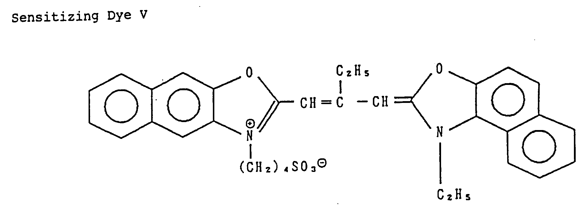


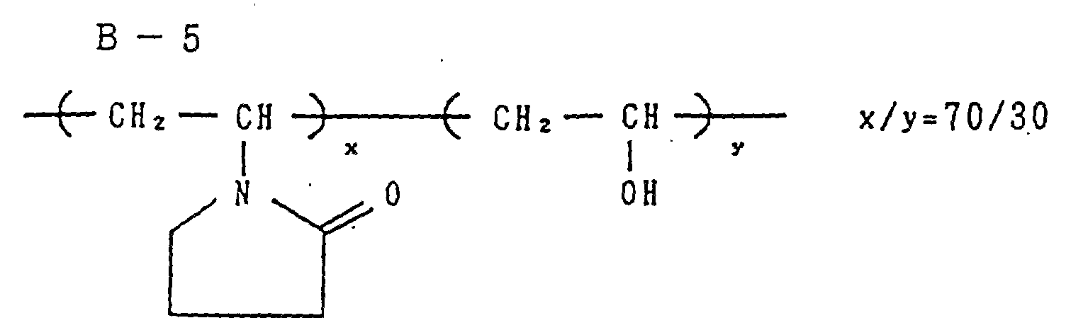


- Samples 102 to 109 were prepared in the same manner as that of the preparation of Sample 101 except that the variety and amount of the fog inhibitor were altered as shown in Table 2.
- The thickness of the hydrophilic colloid layer of Samples 101 to 109 was 21.0 µm.
- Samples 101 to 109 were left to stand at 25 °C at a relative humidity of 65 % for one week and then cut to form slits having a width of 35 mm under the same temperature and humidity conditions as above. The slits were cut to a length of 130 cm and each slit was rolled in a cartridge shown in Fig. 3 to form Samples A-101 to A-109, respectively.
- Samples B-101 to B-109 were prepared in the same manner as described above except that the length of the films in Samples A-101 to A-109 were altered to 145 cm. Samples C-101 to C-109 were prepared in the same manner as described above except that the length of the films were altered to 150 cm. Samples D-101 to D-109 having the film length of 160 cm were prepared in the same manner as above. Although it was tried to roll longer films, the friction in the cartridge was increased to also increase the sending stress.
- The void volumes V of the respective samples are summarized in Table 1.
- A test of sending out the film from the cartridge was conducted wherein the spool of each sample was rotated reversely to the winding drection of the film. The results are shown in Table 1. It is apparent from table 1 that unless the void volume V is reduced to 0.25 or less, the film cannot be stably sent out. The reliability of the sending-out of the film was further increased when V was reduced to 0.22 or less, particularly 0.18 or less.

- Samples A-101 to 109 and D-101 to 109 were kept at 60 °C for 3 days or at room temperature. They were subjected to sensitometric exposure (4800 ° K, 1/100 sec, 2CMS) and then to color development by process A.
- Each of the samples thus processed was subjected to the sensitometry with a green filter to obtain Dmin and sensitivity as shown in Table 2. In Table 2, the sensitivity is given in terms of the absolute value of a reciprocal of an exposure value necessitated for obtaining a density corresponding to (Dmin + 0.2). Dmin represents the density of non-exposed parts.
- It is apparent from Table 2 that when the antifoggant used in the present invention is employed, the fog caused when the void volume is reduced and the photographic film is stored at a high temperature can be minimized.
- Namely, by the effect of the present invention, the preparation of a film cartridge containing a photographic film with a small cartridge which is capable of surely sending out the film is made possible.
- The effect of the present invention was exhibited also in the process B.

-


< Process A > Step Time Temp. Amount of replenisher Capacity of tank Color development 3 min 15 sec 38 °C 33 ml 20 l Bleaching 6 min 30 sec 38 °C 25 ml 40 l Washing with water 2 min 10 sec 24 °C 1200 ml 20 l Fixing 4 min 20 sec38 °C 25 ml 30 l Washing with water (1) 1 min 05 sec 24 °C counter-current from (2) to (1) 10 l Washing with water (2) 1 min 00 sec 24 °C 1200 ml 10 l Stabilization 1 min 05 sec 38 °C 25 ml 10 l Drying 4 min 20 sec55 °C - The amount of replenisher is given per width of 35 mm and length of 1 m.
- The compositions of the processing solutions were as follows:
-
Mother liquor (g) Replenisher (g) Disodium ethylenediaminetetraacetate 0.5 0.7 Sodium sulfite 7.0 8.0 Sodium hydrogensulfite 5.0 5.5 Aqueous ammonium thiosulfate solution (70 %) 170.0 ml 200.0 ml Water ad 1.0 ℓ 1.0 ℓ pH 6.7 6.6 -
Mother liquor (g) Replenisher (g) Formalin (37 %) 2.0 ml 3.0 ml Polyoxyethylene-p-monononylphenyl ether (average degree of polymerization:10) 0.3 0.45 Disodium ethylenediaminetetraacetate 0.05 0.08 Water ad 1.0 ℓ 1.0 ℓ pH 5.0-8.0 5.0-8.0 -
Mother liquor (g) Replenisher (g) Diethylenetriaminepentaacetic acid 1.0 1.1 1-Hydroxyethylidene-1,1-diphosphonic acid 3.0 3.2 Sodium sulfite 4.0 4.4 Potassium carbonate 30.0 37.0 Potassium bromide 1.4 0.7 Potassium iodide 1.5 mg - Hydroxylamine sulfate 2.4 2.8 4-[N-Ethyl-N- β -hydroxyethylamino]-2-methylaniline sulfate 4.5 5.5 Water ad 1.0 ℓ 1.0 ℓ pH 10.05 10.10 -
Mother liquor (g) Replenisher (g) Sodium ferric ethylenediaminetetraacetate trihydrate 100.0 120.0 Disodium ethylenediaminetetraacetate 10.0 11.0 Ammonium bromide 140.0 160.0 Ammonium nitrate 30.0 35.0 Aqueous ammonia (27 %) 6.5 ml 4.0 ml Water ad 1.0 ℓ 1.0 ℓ pH 6.0 5.7 < Process B > Step Time Temp. Amount of replenisher Capacity of tank Color development 3 min 15 sec 38 °C 45 ml 10 ℓ Bleaching 1 min 00 sec 38 ° C 20 ml 4 ℓ Bleach-fixing 3 min 15 sec 38 °C 30 ml 8 ℓ Washing with water (1) 40 sec 35 °C Countercurrent° from (2) to (1) 4 ℓ Washing with water (2) 1 min 00 sec 35 °C 30 ml 4 ℓ Stabilization 40 sec 38 ° C 20 ml 4 ℓ Drying 1 min 15 sec 55 °C - The amount of replenisher is given per width of 35 mm and length of 1 m.
- The compositions of the processing solutions were as follows:


- City water was passed through a column of a mixed-bed system filled with H-type acidic cation exchange resin (Amberlite IR-120B; product of Rohm & Haas Co.) and OH-type anion exchange resin (Amberlite IR-400; product of Rohm & Haas Co.) to reduce calcium and magnesium ion concentration to 3 mg/1ℓ or less. Then 20 mg/ℓ of sodium dichloroisocyanurate and 0.15 g/ ℓ of sodium sulfate were added thereto. pH of the liquid was in the range of 6.5 to 7.5. (Stabilizing solution) [Both mother liquor and replenisher] (g)


-
Ferric ammonium ethylenediaminetetraacetate dihydrate 50.0 Disodium ethylenediaminetetraacetate 5.0 Sodium sulfite 12.0 Aqueous ammonium thiosulfate solution (70 %) 240.0 ml Aqueous ammonia (27 %) 6.0 ml Water ad 1.0 ℓ pH 7.2 - City water was passed through a column of a mixed-bed system filled with H-type acidic cation exchange resin (Amberlite IR-120B; product of Rohm & Haas Co.) and OH-type anion exchange resin (Amberlite IR-400; product of Rohm & Haas Co.) to reduce calcium and magnesium ion concentration to 3 mg/1ℓ or less. Then 20 mg/ℓ of sodium dichloroisocyanurate and 0.15 g/ ℓ of sodium sulfate were added thereto. pH of the liquid was in the range of 6.5 to 7.5. (Stabilizing solution) [Both mother liquor and replenisher] (g)


Claims (7)
- A film cartridge containing a photographic film which comprises a spool, a photographic film engaged with the spool at an end and rolled round the spool and a cartridge body, the whole photographic film being placed in the cartridge, wherein the void volume V in the cartridge which is represented by the following formula is not higher than 0.25, the photographic film comprises at least one photosensitive silver halide emulsion layer formed on a transparent support and the photographic film contains a compound selected from the group consisting of the compounds of the following general formula (I):
 wherein A = (cross-section area of film)
= (thickness of film) x (length of film)B = (cross-sectional area of inside of cartridge)
= (cross-sectional area of cartridge body) - (cross-sectional area of spool)
- The film cartridge of claim 1, wherein the void volume V is 0.04 to 0.22.
- The film cartridge of claim 2, wherein the void volume V is 0.08 to 0.18.
- The film cartridge of claim 1, wherein the total amount of the compound incorporated into the photographic film is 10-6 to 10-1 mol per 1 mol of silver halide contained in the photographic film.
- The film cartridge of claim 4, wherein the total amount of the compound is 10-5 to 10-2 mol per 1 mol of silver halide.
- The film cartridge of claim 1, wherein silver halide incorporated into the photographic film comprises silver bromoiodide, silver chloroiodide or silver chlorobromoiodide, which contain about 20 molar % or less of silver iodide.
- The film cartridge of claim 6, wherein silver halide comprises silver bromoiodide or silver chlorobromoiodide, which contains about 2 to 25 molar % of silver iodide.
Applications Claiming Priority (2)
| Application Number | Priority Date | Filing Date | Title |
|---|---|---|---|
| JP104727/90 | 1990-04-20 | ||
| JP10472790A JPH043051A (en) | 1990-04-20 | 1990-04-20 | Package for photographic sensitive material |
Publications (3)
| Publication Number | Publication Date |
|---|---|
| EP0452811A2 EP0452811A2 (en) | 1991-10-23 |
| EP0452811A3 EP0452811A3 (en) | 1991-12-11 |
| EP0452811B1 true EP0452811B1 (en) | 1996-07-10 |
Family
ID=14388531
Family Applications (1)
| Application Number | Title | Priority Date | Filing Date |
|---|---|---|---|
| EP19910105765 Expired - Lifetime EP0452811B1 (en) | 1990-04-20 | 1991-04-11 | Package of photosensitive material |
Country Status (3)
| Country | Link |
|---|---|
| EP (1) | EP0452811B1 (en) |
| JP (1) | JPH043051A (en) |
| DE (1) | DE69120714T2 (en) |
Families Citing this family (1)
| Publication number | Priority date | Publication date | Assignee | Title |
|---|---|---|---|---|
| JPH05210201A (en) * | 1992-01-31 | 1993-08-20 | Konica Corp | Miniaturized roll film cartridge for photograph and film camera |
Family Cites Families (7)
| Publication number | Priority date | Publication date | Assignee | Title |
|---|---|---|---|---|
| JPS60153039A (en) * | 1984-01-20 | 1985-08-12 | Fuji Photo Film Co Ltd | Photosensitive silver halide material |
| JPS6221527A (en) * | 1985-07-22 | 1987-01-29 | Sekisui Plastics Co Ltd | Manufacture of thermoplastic resin-foamed plate |
| JPS6424250A (en) * | 1987-07-21 | 1989-01-26 | Fuji Photo Film Co Ltd | Wrapping unit for photosensitive material with endowed exposure function |
| JPH0243536A (en) * | 1988-08-03 | 1990-02-14 | Fuji Photo Film Co Ltd | Wrapping unit for photosensitive material |
| US4860037A (en) * | 1988-09-12 | 1989-08-22 | Eastman Kodak Company | Film cassette with magnetic film leader |
| US4887776A (en) * | 1989-03-08 | 1989-12-19 | Eastman Kodak Company | Film cassette |
| US4883236A (en) * | 1989-03-08 | 1989-11-28 | Eastman Kodak Company | Film cassette |
-
1990
- 1990-04-20 JP JP10472790A patent/JPH043051A/en active Pending
-
1991
- 1991-04-11 EP EP19910105765 patent/EP0452811B1/en not_active Expired - Lifetime
- 1991-04-11 DE DE1991620714 patent/DE69120714T2/en not_active Expired - Fee Related
Also Published As
| Publication number | Publication date |
|---|---|
| JPH043051A (en) | 1992-01-08 |
| DE69120714T2 (en) | 1996-12-05 |
| DE69120714D1 (en) | 1996-08-14 |
| EP0452811A2 (en) | 1991-10-23 |
| EP0452811A3 (en) | 1991-12-11 |
Similar Documents
| Publication | Publication Date | Title |
|---|---|---|
| JP2794503B2 (en) | Silver halide color photographic materials | |
| US5148198A (en) | Lens-fitted photographic film unit, a processor for processing the same, and a processing system therefor | |
| JP2955683B2 (en) | Silver halide color photographic materials | |
| EP0452811B1 (en) | Package of photosensitive material | |
| JP2687189B2 (en) | Silver halide color photographic materials | |
| EP0499279A1 (en) | Silver halide color photographic photosensitive material | |
| JPH0553241A (en) | Silver halide photographic sensitive material | |
| EP0476327B1 (en) | Data-retainable photographic film product and process for producing color print | |
| JP2618743B2 (en) | Processing method of silver halide color photographic light-sensitive material | |
| JP2772885B2 (en) | Silver halide color photographic materials | |
| JP2726777B2 (en) | Silver halide photographic material | |
| JPH02220041A (en) | Photosensitive material packaging unit with photographing function | |
| JP2681419B2 (en) | Silver halide photographic material | |
| JP2565386B2 (en) | Silver halide color photographic light-sensitive material | |
| JP2964015B2 (en) | Silver halide color photographic materials | |
| JP2772877B2 (en) | Silver halide color photographic materials | |
| JP2715335B2 (en) | Processing method of silver halide color photographic light-sensitive material | |
| JP2896453B2 (en) | Photographic processing apparatus and processing method | |
| JP2879488B2 (en) | Silver halide color photographic materials | |
| JPH0627601A (en) | Photographic film product | |
| JPH04159538A (en) | Silver halide photographic sensitive material | |
| JPH06138594A (en) | Photographic film product | |
| JPH03153241A (en) | Photosensitive material packaging unit with photographing function | |
| JPH04350849A (en) | Silver halide photographic sensitive material | |
| JPH06258788A (en) | Photographic product |
Legal Events
| Date | Code | Title | Description |
|---|---|---|---|
| PUAI | Public reference made under article 153(3) epc to a published international application that has entered the european phase |
Free format text: ORIGINAL CODE: 0009012 |
|
| PUAL | Search report despatched |
Free format text: ORIGINAL CODE: 0009013 |
|
| AK | Designated contracting states |
Kind code of ref document: A2 Designated state(s): DE FR GB IT NL |
|
| AK | Designated contracting states |
Kind code of ref document: A3 Designated state(s): DE FR GB IT NL |
|
| 17P | Request for examination filed |
Effective date: 19920218 |
|
| 17Q | First examination report despatched |
Effective date: 19950222 |
|
| GRAH | Despatch of communication of intention to grant a patent |
Free format text: ORIGINAL CODE: EPIDOS IGRA |
|
| GRAH | Despatch of communication of intention to grant a patent |
Free format text: ORIGINAL CODE: EPIDOS IGRA |
|
| GRAA | (expected) grant |
Free format text: ORIGINAL CODE: 0009210 |
|
| AK | Designated contracting states |
Kind code of ref document: B1 Designated state(s): DE FR GB IT NL |
|
| PG25 | Lapsed in a contracting state [announced via postgrant information from national office to epo] |
Ref country code: IT Free format text: LAPSE BECAUSE OF FAILURE TO SUBMIT A TRANSLATION OF THE DESCRIPTION OR TO PAY THE FEE WITHIN THE PRE;WARNING: LAPSES OF ITALIAN PATENTS WITH EFFECTIVE DATE BEFORE 2007 MAY HAVE OCCURRED AT ANY TIME BEFORE 2007. THE CORRECT EFFECTIVE DATE MAY BE DIFFERENT FROM THE ONE RECORDED.SCRIBED TIME-LIMIT Effective date: 19960710 Ref country code: NL Free format text: LAPSE BECAUSE OF FAILURE TO SUBMIT A TRANSLATION OF THE DESCRIPTION OR TO PAY THE FEE WITHIN THE PRESCRIBED TIME-LIMIT Effective date: 19960710 Ref country code: FR Effective date: 19960710 |
|
| REF | Corresponds to: |
Ref document number: 69120714 Country of ref document: DE Date of ref document: 19960814 |
|
| NLV1 | Nl: lapsed or annulled due to failure to fulfill the requirements of art. 29p and 29m of the patents act | ||
| EN | Fr: translation not filed | ||
| PLBE | No opposition filed within time limit |
Free format text: ORIGINAL CODE: 0009261 |
|
| STAA | Information on the status of an ep patent application or granted ep patent |
Free format text: STATUS: NO OPPOSITION FILED WITHIN TIME LIMIT |
|
| 26N | No opposition filed | ||
| REG | Reference to a national code |
Ref country code: GB Ref legal event code: IF02 |
|
| PGFP | Annual fee paid to national office [announced via postgrant information from national office to epo] |
Ref country code: GB Payment date: 20040401 Year of fee payment: 14 |
|
| PG25 | Lapsed in a contracting state [announced via postgrant information from national office to epo] |
Ref country code: GB Free format text: LAPSE BECAUSE OF NON-PAYMENT OF DUE FEES Effective date: 20050411 |
|
| GBPC | Gb: european patent ceased through non-payment of renewal fee |
Effective date: 20050411 |
|
| PGFP | Annual fee paid to national office [announced via postgrant information from national office to epo] |
Ref country code: DE Payment date: 20080417 Year of fee payment: 18 |
|
| PG25 | Lapsed in a contracting state [announced via postgrant information from national office to epo] |
Ref country code: DE Free format text: LAPSE BECAUSE OF NON-PAYMENT OF DUE FEES Effective date: 20091103 |