EP0452819A1 - Dispositif d'application, particulièrement pulvérisateur ou générateur d'aérosol - Google Patents
Dispositif d'application, particulièrement pulvérisateur ou générateur d'aérosol Download PDFInfo
- Publication number
- EP0452819A1 EP0452819A1 EP91105812A EP91105812A EP0452819A1 EP 0452819 A1 EP0452819 A1 EP 0452819A1 EP 91105812 A EP91105812 A EP 91105812A EP 91105812 A EP91105812 A EP 91105812A EP 0452819 A1 EP0452819 A1 EP 0452819A1
- Authority
- EP
- European Patent Office
- Prior art keywords
- discharge line
- active substance
- shut
- monitoring element
- liquid
- Prior art date
- Legal status (The legal status is an assumption and is not a legal conclusion. Google has not performed a legal analysis and makes no representation as to the accuracy of the status listed.)
- Granted
Links
- 239000000443 aerosol Substances 0.000 title claims description 4
- 239000011248 coating agent Substances 0.000 title 1
- 238000000576 coating method Methods 0.000 title 1
- 239000007788 liquid Substances 0.000 claims abstract description 63
- 239000013543 active substance Substances 0.000 claims abstract description 52
- 238000012544 monitoring process Methods 0.000 claims abstract description 11
- 238000004140 cleaning Methods 0.000 claims description 57
- 239000007921 spray Substances 0.000 claims description 24
- 238000000034 method Methods 0.000 claims description 12
- XLYOFNOQVPJJNP-UHFFFAOYSA-N water Substances O XLYOFNOQVPJJNP-UHFFFAOYSA-N 0.000 claims description 9
- 238000011010 flushing procedure Methods 0.000 claims description 7
- 238000011109 contamination Methods 0.000 abstract description 5
- 239000012530 fluid Substances 0.000 abstract description 5
- 239000007787 solid Substances 0.000 abstract description 4
- 239000002245 particle Substances 0.000 abstract 1
- 230000005236 sound signal Effects 0.000 abstract 1
- 239000012528 membrane Substances 0.000 description 10
- 230000006835 compression Effects 0.000 description 7
- 238000007906 compression Methods 0.000 description 7
- 230000000694 effects Effects 0.000 description 3
- 239000004480 active ingredient Substances 0.000 description 2
- 239000003814 drug Substances 0.000 description 2
- 229940079593 drug Drugs 0.000 description 2
- 239000003518 caustics Substances 0.000 description 1
- 239000012459 cleaning agent Substances 0.000 description 1
- 230000007423 decrease Effects 0.000 description 1
- 230000001419 dependent effect Effects 0.000 description 1
- 230000005484 gravity Effects 0.000 description 1
- 238000009434 installation Methods 0.000 description 1
- 238000005259 measurement Methods 0.000 description 1
- 238000012806 monitoring device Methods 0.000 description 1
- 239000000126 substance Substances 0.000 description 1
- 238000011144 upstream manufacturing Methods 0.000 description 1
Images


Classifications
-
- B—PERFORMING OPERATIONS; TRANSPORTING
- B05—SPRAYING OR ATOMISING IN GENERAL; APPLYING FLUENT MATERIALS TO SURFACES, IN GENERAL
- B05B—SPRAYING APPARATUS; ATOMISING APPARATUS; NOZZLES
- B05B12/00—Arrangements for controlling delivery; Arrangements for controlling the spray area
Definitions
- the invention relates to a discharge device, in particular a spray or aerosol generator, according to the preamble of claim 1.
- the flow control of liquids is usually carried out with devices that operate on the float principle, with turbine meters, with baffle plates or e.g. work with panels.
- These measuring methods have the disadvantage that liquids which are mixed or enriched with solids can lead to blockages and / or soiling in the measuring devices.
- These measuring devices are also not or only difficult to clean due to their fine mechanical structure. When liquids have dried up, the residues lead to incrustations, so that measurements can no longer be carried out.
- the invention has for its object to design the generic discharge device so that the flow of the active ingredient liquid through the discharge line simply over a can be monitored for a long period of time without the risk of blockages and / or contamination of the monitoring device.
- the liquid level in the active substance tank is checked by the monitoring element. As soon as the active substance tank falls below a predetermined level when the active substance liquid is discharged, this is determined by the monitoring element. It then sends a switching signal to the rinsing device, which is automatically started and rinses the discharge line immediately after discharge. This prevents in a very simple manner that the active substances in the active substance liquid settle in the discharge line and lead to contamination or even incrustation. As a result of the automatic flushing of the discharge line, it is ensured that the active substance liquid can be sprayed out perfectly with the discharge device according to the invention.
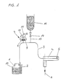
- the discharge device is preferably a spray or aerosol generator with which liquids which are mixed or enriched with solids are discharged from a tank 1.
- a preferably height-adjustable suction tube 2 projects into it and is connected to a discharge line 3. It connects the suction pipe 2 to a spray device 4, with which the active substance liquid is discharged through a nozzle 5 which is connected to the discharge line 3.
- Air is blown in the direction of arrow 6 at high speed by the spray device 4.
- a negative pressure is generated, as a result of which the active substance liquid is sucked out of the active substance tank 1.
- the negative pressure in the discharge line 3 and in the active substance tank 1 can of course also be generated in any other suitable way.
- the drug tank 1 is not sealed in a known manner, so that no negative pressure can form in the drug tank 1.
- the membrane 8 of the switching element 7 is under the force of a compression spring 9, which loads the membrane 8 in the direction of its central position.
- the membrane 8 carries on its side facing away from the compression spring 9 a switching plunger 10 with which a switching lever 11 can be pivoted when the membrane 8 is deflected in order to close or open an electrical contact 12.
- the space 13 of the switching element 7 which has the compression spring 9 is connected to the discharge line 3 via an intermediate line 14.
- the intermediate line 14, however, has a substantially smaller cross-section than the discharge line 3, so that there is no risk that part of the active substance liquid will get into the switching element 7 via the intermediate line 14 during discharge.
- a container 16 for a cleaning liquid is connected to the discharge line 3 in the flow direction behind the intermediate line 14 via a connecting line 15.
- a shut-off device 17 which in Embodiment according to FIGS. 1 and 2 is a solenoid valve. During the discharge of the active substance liquid, the shut-off element 17 is closed, so that the cleaning liquid cannot flow out of the container 16 into the discharge line 3.
- the membrane of the switching element 7 is elastically deformed against the force of the compression spring 9 in the direction of the intermediate line 14.
- the shift lever 11 is entrained by the shift plunger 10, whereby the switch 12 is opened.
- the active substance liquid is sucked out of the active substance tank 1 and sprayed.
- the negative pressure in the active substance tank 1 and in the discharge line 3 drops.
- the compression spring 9 of the switching element 7 can then adjust the membrane 8 again in the direction of its central position. Via the switching plunger 10, the switching lever 11 is adjusted so that the switch 12 is closed.
- the connections for the switching element 7 and the shut-off element 17 for the container 16 are provided on a screw part 19 which is detachably inserted into the discharge line 3 and, if necessary, for example for repair purposes of the switching element and / or the shut-off element 17 and / or the container 16, can be easily replaced.
- the screw part 19 has threaded sections 20 and 21 at its two ends, into which corresponding thread ends of the discharge line 3 can be screwed.
- the cleaning process is automatically initiated in the manner described.
- the cleaning process can also be ended automatically, for example by means of a timer which determines the duration of the cleaning process.
- This timer can be designed to be adjustable so that the duration of the cleaning process can be set depending on the active ingredient used.
- it is also possible to switch off the cleaning process for example by hand, by moving the shut-off device 17 into its closed position.
- the suction device with which the air is sucked into the spray device 4 for generating the negative pressure must be switched on by hand.
- the cleaning container 16 as shown in FIG. 1, is located in the area above the discharge line 3 and is designed as a pressureless container.
- the discharge line 3 is rinsed by utilizing the geodetic height of the cleaning container 16 in relation to the discharge line 3 after opening the shut-off member 17.
- the switch 12 is closed and the shut-off member 17 is opened in the manner described is, the cleaning liquid flows from the container 16 under gravity through the connecting line 15 into the discharge line 3 to the spray nozzle 5.
- the area of the discharge line 3 between the connecting line 15 and the spray nozzle 5 is rinsed and cleaned.
- the shut-off element 17, in particular the cross section of the connecting line 15, is selected so that more cleaning liquid can flow from the container 16 than is suctioned off at the spray nozzle 5 . Due to the line resistance, the cleaning liquid thus flows against the direction of flow in the discharge line 3 back into the suction pipe 2 and into the active substance tank 1, so that in this case the entire discharge line 3 including the suction pipe 2 is excellently rinsed and cleaned. This reliably prevents active substances from settling in the discharge line 3, in the suction pipe 2 and in the spray nozzle or in the spray head 5 and prevent or at least impair the discharge of the active substance.
- FIG 4a schematically shows the case in which the shut-off device 17 is closed and the active substance thus flows in the discharge line 3 in the suction direction 22.
- the cleaning liquid can also be supplied intermittently in order to obtain a better cleaning effect.
- the shut-off device 17 is opened and closed in a pulsed manner.
- air (closed shut-off device 17) and cleaning fluid (open shut-off device 17) are sucked in intermittently, whereby a better cleaning effect is achieved while at the same time saving cleaning fluid.
- the shut-off device is closed during this pulse cleaning, then air is sucked out of the active substance tank, in which the liquid level 18 has dropped so far that the free end of the suction pipe 2 is free.
- cleaning liquid is sucked out of the container 16.
- the switching element 7 designed as a pressure switch is arranged in the area above the active substance tank 1 and in the area above the discharge line 3. This also ensures that the switching element 7 or its membrane 8 does not come into contact with the possibly corrosive medium to be discharged.
- the vacuum or pressure switch 7 drops out in the manner described and initiates the rinsing process in the manner described.
- the electrical sequence program is switched on by switching this switching element 7.
- the container 16a is designed as a pressurized container.
- it is provided with a pressure connection 23 so that the cleaning liquid can be conveyed into the discharge line 3 by means of pressurization via the connecting line 15.
- the cleaning container 16a does not have to be arranged in the region above the active substance tank 1 or the discharge line 3.
- the discharge line 3 is reliably cleaned or flushed.
- the cleaning with such a pressure container 16a takes place in the same way as has been explained in detail with the aid of the previous exemplary embodiment.
- the shut-off device 17 is in each case a two-way valve.
- a three-way valve 17b can also be used as a shut-off device (FIGS. 3b and 3c).
- Such a three-way valve 17b like the two-way valve 17, is arranged such that it does not come into contact with the possibly corrosive agent to be discharged.
- the three-way valve 17b is closed, so that the active substance in solution form 1 in the active substance tank 1 passes through the discharge line by means of negative pressure is carried out.
- the switch 12 is actuated by the switching element 7 in the manner described and the three-way valve 17b is thus adjusted to the open position (FIG. 3b).
- the cleaning liquid can flow from the container 16b via the connecting line 15 into the discharge line 3 in the manner described.
- the container 16b can in turn work without pressure or be provided with a pressure connection, so that the cleaning liquid is pressed under pressure through the connecting line 15 into the discharge line 3.
- the dimensions of the connecting line 15 and the discharge line 3 with the spray head 5 can be chosen such that the cleaning liquid flows into the suction pipe 2 and into the active substance tank 1 counter to the suction direction 22.
- the three-way valve 17b With the three-way valve 17b, it is particularly easy to carry out pulse cleaning.
- the three-way valve 17b is switched over at short time intervals so that cleaning fluid and air alternately reach the discharge line 3 via the connecting line 15.
- the three-way valve 17b is switched so that the container-side port 25 of the three-way valve 17b is closed and the air is sucked in via an atmosphere-side port 26.
- the atmosphere-side connection 24 of the three-way valve 17b can also be used to connect a second cleaning container. Additional cleaning liquid or another liquid can be stored in it. In this way, this additional or further cleaning liquid can be conveyed into the discharge line 3 by switching the three-way valve 17b.
- the switching element 7 is located in the suction direction 22 of the active substance behind the shut-off element 17c, which in turn is a three-way valve in the exemplary embodiment shown.
- a two-way valve according to FIGS. 1 and 2 can of course also be used.
- the three-way valve 17c has two connections 27 and 28 for the discharge line 3 and a connection 29 for the connecting line 15, which leads to the container 16c with the cleaning liquid.
- the two connections 27 and 28 are located in the discharge line 3.
- this embodiment is of the same design as the exemplary embodiments described above.
- the embodiment according to FIG. 5 is used in particular with residue-free or solids-free substances.
- the connections 28 and 29 of the three-way valve are open, so that the cleaning liquid is sucked out of the pressureless or pressurized container 16c via the connecting line 15 into the discharge line 3 up to the spray head 5.
- the connection 27 of the three-way valve 17c directed against the flow direction 22 is blocked.
- the discharge line 3 is not rinsed and cleaned in the area between the three-way valve and the active substance tank 1.
- the two connections 27 and 29 of the three-way valve 17c are open, while the connection 28 on the container side is blocked.
- the three-way valve 17c assumes this position during the discharge of the active substance.
- the liquid in the active substance tank 1 is conveyed in the suction direction 22 in the manner described by negative pressure to the spray nozzle 5.
- the two connections 27 and 28 are open, while the connection 29 of the three-way valve 17c is blocked.
- the cleaning liquid is conveyed through the suction pipe 2 into the active substance tank 1.
- the flushing or cleaning can also be carried out without pressure or with pressure, as in the position according to FIG.
- the installation position of the container is not dependent on the geodetic height, as has also been explained using the exemplary embodiment according to FIG. 3a.
- the embodiment according to FIG. 5 works in the same way as the embodiment according to FIG. 1. Air is sucked into the spray device 4, which flows through the spray device at high speed and thereby sucks the active substance out of the spray nozzle 5. As a result of the high air speed, a negative pressure is generated in the discharge line 3 and thus in the suction pipe 2 and in the active substance tank 1, through which the active substance is sprayed. As a result of the negative pressure, the membrane 8 of the switching element 7 becomes counter to the force of the compression spring 3 bent elastically, whereby the switch 12 is opened in the manner described. As soon as the liquid level in the active substance tank 1 falls below the free end of the suction pipe 2, the negative pressure decreases, which is sufficient for the compression spring 9 to return the membrane 8 to its initial position.
- the switch 12 is closed via the switching plunger 10 and the switching lever 11, whereby the shut-off device 17c is opened so that the cleaning liquid can get into the discharge line 3.
- the three-way valve 17c is first opened in accordance with FIG. 6a, so that the discharge line 3 is rinsed and cleaned from the three-way valve 17c to the spray head 5.
- the three-way valve 17c is then switched to the position according to FIG. 6c by means of a timer or also manually, so that the discharge line 3 in the region between the three-way valve and the active substance tank 1 is now also cleaned.
- the cleaning liquid is sucked out of the container 16c by the negative pressure present in the discharge line 3. If the container 16c is under pressure, the suction effect of the discharge device is supported by the pressurization, so that the cleaning liquid reliably rinses the discharge line 3.
- the three-way valves 17b, 17c described are commercially available 3/2-way valves, but can also be corresponding ball valves with which the various valve positions can be achieved.
- the described arrangement of the switching element 7 in the flow direction 22 behind the shut-off device 17c can also be provided in the previously described exemplary embodiments. It is also possible to arrange the switching element 7 in the suction direction 22 in front of the shut-off device 17c in the exemplary embodiment according to FIG. 5. Finally, the shut-off element in the embodiment according to FIG. 5 can be designed in the same way as in the previously described exemplary embodiments, while conversely the shut-off element according to FIG. 5 can also be used in the previous exemplary embodiments.
- the connecting line 15 to the cleaning container can also be connected directly to the water network, so that water can be removed directly from the water network as cleaning liquid. It is also possible to connect the container to the water network so that water can be removed directly from the water network via the container as a cleaning agent.
Landscapes
- Cleaning By Liquid Or Steam (AREA)
- Lubricants (AREA)
- Medicinal Preparation (AREA)
- Agricultural Chemicals And Associated Chemicals (AREA)
- Feeding, Discharge, Calcimining, Fusing, And Gas-Generation Devices (AREA)
Applications Claiming Priority (2)
| Application Number | Priority Date | Filing Date | Title |
|---|---|---|---|
| DE4012433 | 1990-04-19 | ||
| DE4012433A DE4012433A1 (de) | 1990-04-19 | 1990-04-19 | Austragvorrichtung, insbesondere sprueh- oder aerosolgenerator |
Publications (2)
| Publication Number | Publication Date |
|---|---|
| EP0452819A1 true EP0452819A1 (fr) | 1991-10-23 |
| EP0452819B1 EP0452819B1 (fr) | 1994-07-20 |
Family
ID=6404632
Family Applications (1)
| Application Number | Title | Priority Date | Filing Date |
|---|---|---|---|
| EP91105812A Expired - Lifetime EP0452819B1 (fr) | 1990-04-19 | 1991-04-12 | Dispositif d'application, particulièrement pulvérisateur ou générateur d'aérosol |
Country Status (5)
| Country | Link |
|---|---|
| EP (1) | EP0452819B1 (fr) |
| AT (1) | ATE108702T1 (fr) |
| DE (2) | DE4012433A1 (fr) |
| DK (1) | DK0452819T3 (fr) |
| ES (1) | ES2056513T3 (fr) |
Citations (4)
| Publication number | Priority date | Publication date | Assignee | Title |
|---|---|---|---|---|
| US3674205A (en) * | 1971-05-14 | 1972-07-04 | Champion Spark Plug Co | Multiple color paint spray system |
| US4592305A (en) * | 1981-01-26 | 1986-06-03 | Ransburg Corporation | Variable low-pressure fluid color change cycle |
| US4714179A (en) * | 1985-03-15 | 1987-12-22 | Ford Motor Company | Positive displacement paint pushout apparatus |
| DD255483A5 (de) * | 1986-11-06 | 1988-04-06 | ��������@���������������@����������������������@���k�� | Spruehvorrichtung, insbesondere fuer die flaechenproportionale verspruehung |
-
1990
- 1990-04-19 DE DE4012433A patent/DE4012433A1/de not_active Withdrawn
-
1991
- 1991-04-12 EP EP91105812A patent/EP0452819B1/fr not_active Expired - Lifetime
- 1991-04-12 ES ES91105812T patent/ES2056513T3/es not_active Expired - Lifetime
- 1991-04-12 DE DE59102217T patent/DE59102217D1/de not_active Expired - Fee Related
- 1991-04-12 AT AT91105812T patent/ATE108702T1/de not_active IP Right Cessation
- 1991-04-12 DK DK91105812.1T patent/DK0452819T3/da active
Patent Citations (4)
| Publication number | Priority date | Publication date | Assignee | Title |
|---|---|---|---|---|
| US3674205A (en) * | 1971-05-14 | 1972-07-04 | Champion Spark Plug Co | Multiple color paint spray system |
| US4592305A (en) * | 1981-01-26 | 1986-06-03 | Ransburg Corporation | Variable low-pressure fluid color change cycle |
| US4714179A (en) * | 1985-03-15 | 1987-12-22 | Ford Motor Company | Positive displacement paint pushout apparatus |
| DD255483A5 (de) * | 1986-11-06 | 1988-04-06 | ��������@���������������@����������������������@���k�� | Spruehvorrichtung, insbesondere fuer die flaechenproportionale verspruehung |
Also Published As
| Publication number | Publication date |
|---|---|
| ES2056513T3 (es) | 1994-10-01 |
| DE4012433A1 (de) | 1991-10-24 |
| EP0452819B1 (fr) | 1994-07-20 |
| DK0452819T3 (da) | 1994-09-05 |
| ATE108702T1 (de) | 1994-08-15 |
| DE59102217D1 (de) | 1994-08-25 |
Similar Documents
| Publication | Publication Date | Title |
|---|---|---|
| EP1972442B1 (fr) | Procédé et dispositif de nettoyage de buses sur un dispositif d'humidification à pulvérisation | |
| EP3209834B1 (fr) | Ensemble sanitaire muni d'un dispositif de surveillance | |
| DE2637962C3 (de) | Verfahren zum Abführen der Abwässer von einer Vielzahl von Hausanschlüssen mittels Unterdruck | |
| EP1890823A1 (fr) | Buse de pulverisation, dispositif de pulverisation et procede permettant de faire fonctionner une buse de pulverisation et un dispositif de pulverisation | |
| DE2158469B2 (de) | Dual additive feeder for dishwashing | |
| EP4146367A1 (fr) | Essai de perméabilité automatisé pour panier filtrant | |
| DE69019614T2 (de) | Filter zur automatischen Reinigung von Flüssigkeitskreisläufen. | |
| DE2745498C3 (de) | Vorrichtung zur Steuerung eines Nachfüllens von Flüssigkeit in eine Reinigungsmischung | |
| EP3564454A1 (fr) | Dispositif de séparation permettant d'éliminer des objets d'un courant d'eau et procédé de fonctionnement d'un tel dispositif de séparation | |
| DE10204737A1 (de) | Verfahren und Vorrichtung zum Spülen und Reinigen einer Rohrleitung, insbesondere einer Trinkwasserleitung | |
| EP1988846B1 (fr) | Unité de rinçage dentaire | |
| DE3134861A1 (de) | Magnetfilter mit direktspuelung | |
| EP0452819B1 (fr) | Dispositif d'application, particulièrement pulvérisateur ou générateur d'aérosol | |
| DE2412499C3 (de) | Probenentnahme- und Meßstation zur Überwachung von Flüssigkeiten | |
| EP0421262A2 (fr) | Procédé de traitement d'objets avec un fluide et dispositif de mise en oeuvre de ce procédé | |
| DE19516740C2 (de) | Vakuumtoilettensystem | |
| EP1517213B1 (fr) | Appareil de dosage pour la production à partir de concentrés d'une solution de produit désinfectant prête à l'emploi | |
| DE3236339C2 (de) | Automatische, elektrisch betriebene Luftbefeuchtungsanlage | |
| DE2541147B2 (de) | Vorrichtung zum Eindicken von Trüben | |
| DE9201647U1 (de) | Milchprobenvordosierung für Milchsammelfahrzeuge | |
| DE3510831A1 (de) | Verfahren und vorrichtung zum herstellen einer waschlauge aus einem waschpulver | |
| CH649060A5 (de) | Verfahren und vorrichtung zum foerdern von schuettgut. | |
| DE1810907A1 (de) | Sicherheitsdruckschalter | |
| DE10348441B4 (de) | Pneumatisches Sicherheitsventil für Druckluftsysteme | |
| DE3418703A1 (de) | Vorrichtung zum aufspruehen von erstarrungsverzoegerer auf waschbetonplatten |
Legal Events
| Date | Code | Title | Description |
|---|---|---|---|
| PUAI | Public reference made under article 153(3) epc to a published international application that has entered the european phase |
Free format text: ORIGINAL CODE: 0009012 |
|
| AK | Designated contracting states |
Kind code of ref document: A1 Designated state(s): AT BE CH DE DK ES FR GB GR IT LI LU NL SE |
|
| 17P | Request for examination filed |
Effective date: 19920422 |
|
| 17Q | First examination report despatched |
Effective date: 19930628 |
|
| GRAA | (expected) grant |
Free format text: ORIGINAL CODE: 0009210 |
|
| AK | Designated contracting states |
Kind code of ref document: B1 Designated state(s): AT BE CH DE DK ES FR GB GR IT LI LU NL SE |
|
| PG25 | Lapsed in a contracting state [announced via postgrant information from national office to epo] |
Ref country code: GR Free format text: LAPSE BECAUSE OF FAILURE TO SUBMIT A TRANSLATION OF THE DESCRIPTION OR TO PAY THE FEE WITHIN THE PRESCRIBED TIME-LIMIT Effective date: 19940720 Ref country code: BE Effective date: 19940720 |
|
| REF | Corresponds to: |
Ref document number: 108702 Country of ref document: AT Date of ref document: 19940815 Kind code of ref document: T |
|
| REF | Corresponds to: |
Ref document number: 59102217 Country of ref document: DE Date of ref document: 19940825 |
|
| REG | Reference to a national code |
Ref country code: DK Ref legal event code: T3 |
|
| REG | Reference to a national code |
Ref country code: ES Ref legal event code: FG2A Ref document number: 2056513 Country of ref document: ES Kind code of ref document: T3 |
|
| ITF | It: translation for a ep patent filed | ||
| ET | Fr: translation filed | ||
| GBT | Gb: translation of ep patent filed (gb section 77(6)(a)/1977) |
Effective date: 19941028 |
|
| EAL | Se: european patent in force in sweden |
Ref document number: 91105812.1 |
|
| PGFP | Annual fee paid to national office [announced via postgrant information from national office to epo] |
Ref country code: GB Payment date: 19950404 Year of fee payment: 5 |
|
| PG25 | Lapsed in a contracting state [announced via postgrant information from national office to epo] |
Ref country code: AT Effective date: 19950412 |
|
| PG25 | Lapsed in a contracting state [announced via postgrant information from national office to epo] |
Ref country code: LU Free format text: LAPSE BECAUSE OF NON-PAYMENT OF DUE FEES Effective date: 19950430 Ref country code: LI Effective date: 19950430 Ref country code: CH Effective date: 19950430 |
|
| PGFP | Annual fee paid to national office [announced via postgrant information from national office to epo] |
Ref country code: DK Payment date: 19950501 Year of fee payment: 5 |
|
| PLBE | No opposition filed within time limit |
Free format text: ORIGINAL CODE: 0009261 |
|
| STAA | Information on the status of an ep patent application or granted ep patent |
Free format text: STATUS: NO OPPOSITION FILED WITHIN TIME LIMIT |
|
| 26N | No opposition filed | ||
| REG | Reference to a national code |
Ref country code: CH Ref legal event code: PL |
|
| PG25 | Lapsed in a contracting state [announced via postgrant information from national office to epo] |
Ref country code: GB Effective date: 19960412 Ref country code: DK Effective date: 19960412 |
|
| REG | Reference to a national code |
Ref country code: DK Ref legal event code: EBP |
|
| GBPC | Gb: european patent ceased through non-payment of renewal fee |
Effective date: 19960412 |
|
| PGFP | Annual fee paid to national office [announced via postgrant information from national office to epo] |
Ref country code: FR Payment date: 19970312 Year of fee payment: 7 |
|
| PGFP | Annual fee paid to national office [announced via postgrant information from national office to epo] |
Ref country code: ES Payment date: 19970404 Year of fee payment: 7 |
|
| PGFP | Annual fee paid to national office [announced via postgrant information from national office to epo] |
Ref country code: SE Payment date: 19970424 Year of fee payment: 7 |
|
| PGFP | Annual fee paid to national office [announced via postgrant information from national office to epo] |
Ref country code: NL Payment date: 19970430 Year of fee payment: 7 |
|
| PGFP | Annual fee paid to national office [announced via postgrant information from national office to epo] |
Ref country code: DE Payment date: 19970618 Year of fee payment: 7 |
|
| PG25 | Lapsed in a contracting state [announced via postgrant information from national office to epo] |
Ref country code: SE Free format text: LAPSE BECAUSE OF NON-PAYMENT OF DUE FEES Effective date: 19980413 Ref country code: ES Free format text: LAPSE BECAUSE OF EXPIRATION OF PROTECTION Effective date: 19980413 |
|
| PG25 | Lapsed in a contracting state [announced via postgrant information from national office to epo] |
Ref country code: FR Free format text: THE PATENT HAS BEEN ANNULLED BY A DECISION OF A NATIONAL AUTHORITY Effective date: 19980430 |
|
| PG25 | Lapsed in a contracting state [announced via postgrant information from national office to epo] |
Ref country code: NL Free format text: LAPSE BECAUSE OF NON-PAYMENT OF DUE FEES Effective date: 19981101 |
|
| NLV4 | Nl: lapsed or anulled due to non-payment of the annual fee |
Effective date: 19981101 |
|
| EUG | Se: european patent has lapsed |
Ref document number: 91105812.1 |
|
| PG25 | Lapsed in a contracting state [announced via postgrant information from national office to epo] |
Ref country code: DE Free format text: LAPSE BECAUSE OF NON-PAYMENT OF DUE FEES Effective date: 19990202 |
|
| REG | Reference to a national code |
Ref country code: FR Ref legal event code: ST |
|
| REG | Reference to a national code |
Ref country code: ES Ref legal event code: FD2A Effective date: 20000301 |
|
| PG25 | Lapsed in a contracting state [announced via postgrant information from national office to epo] |
Ref country code: IT Free format text: LAPSE BECAUSE OF NON-PAYMENT OF DUE FEES;WARNING: LAPSES OF ITALIAN PATENTS WITH EFFECTIVE DATE BEFORE 2007 MAY HAVE OCCURRED AT ANY TIME BEFORE 2007. THE CORRECT EFFECTIVE DATE MAY BE DIFFERENT FROM THE ONE RECORDED. Effective date: 20050412 |