EP0452911A1 - Blattzuführvorrichtung - Google Patents
Blattzuführvorrichtung Download PDFInfo
- Publication number
- EP0452911A1 EP0452911A1 EP91106162A EP91106162A EP0452911A1 EP 0452911 A1 EP0452911 A1 EP 0452911A1 EP 91106162 A EP91106162 A EP 91106162A EP 91106162 A EP91106162 A EP 91106162A EP 0452911 A1 EP0452911 A1 EP 0452911A1
- Authority
- EP
- European Patent Office
- Prior art keywords
- paper
- cylinder
- document
- suction
- paper feed
- Prior art date
- Legal status (The legal status is an assumption and is not a legal conclusion. Google has not performed a legal analysis and makes no representation as to the accuracy of the status listed.)
- Withdrawn
Links
- 230000002093 peripheral effect Effects 0.000 claims abstract description 27
- 230000007246 mechanism Effects 0.000 claims abstract description 7
- 238000000034 method Methods 0.000 claims description 16
- 239000000463 material Substances 0.000 claims description 6
- 230000004044 response Effects 0.000 claims description 2
- 239000011521 glass Substances 0.000 description 21
- 230000001105 regulatory effect Effects 0.000 description 19
- 230000008569 process Effects 0.000 description 10
- 230000003287 optical effect Effects 0.000 description 6
- PXHVJJICTQNCMI-UHFFFAOYSA-N Nickel Chemical compound [Ni] PXHVJJICTQNCMI-UHFFFAOYSA-N 0.000 description 4
- 230000000149 penetrating effect Effects 0.000 description 4
- 229910000838 Al alloy Inorganic materials 0.000 description 3
- 230000009471 action Effects 0.000 description 3
- 238000004519 manufacturing process Methods 0.000 description 3
- 238000004064 recycling Methods 0.000 description 3
- PPBRXRYQALVLMV-UHFFFAOYSA-N Styrene Chemical compound C=CC1=CC=CC=C1 PPBRXRYQALVLMV-UHFFFAOYSA-N 0.000 description 2
- 238000005299 abrasion Methods 0.000 description 2
- 229920001971 elastomer Polymers 0.000 description 2
- 238000005323 electroforming Methods 0.000 description 2
- 238000005530 etching Methods 0.000 description 2
- 230000033001 locomotion Effects 0.000 description 2
- 229910052759 nickel Inorganic materials 0.000 description 2
- 238000003825 pressing Methods 0.000 description 2
- 229920005989 resin Polymers 0.000 description 2
- 239000011347 resin Substances 0.000 description 2
- 239000005060 rubber Substances 0.000 description 2
- 238000001179 sorption measurement Methods 0.000 description 2
- 239000010935 stainless steel Substances 0.000 description 2
- 229910001220 stainless steel Inorganic materials 0.000 description 2
- 230000001360 synchronised effect Effects 0.000 description 2
- 229920003051 synthetic elastomer Polymers 0.000 description 2
- 239000005061 synthetic rubber Substances 0.000 description 2
- 229920002943 EPDM rubber Polymers 0.000 description 1
- 229920000181 Ethylene propylene rubber Polymers 0.000 description 1
- YCKRFDGAMUMZLT-UHFFFAOYSA-N Fluorine atom Chemical compound [F] YCKRFDGAMUMZLT-UHFFFAOYSA-N 0.000 description 1
- 239000005062 Polybutadiene Substances 0.000 description 1
- 229920006311 Urethane elastomer Polymers 0.000 description 1
- 229920000800 acrylic rubber Polymers 0.000 description 1
- 238000005452 bending Methods 0.000 description 1
- 230000033228 biological regulation Effects 0.000 description 1
- 229920005549 butyl rubber Polymers 0.000 description 1
- 230000008859 change Effects 0.000 description 1
- 238000010073 coating (rubber) Methods 0.000 description 1
- 239000011248 coating agent Substances 0.000 description 1
- 238000000576 coating method Methods 0.000 description 1
- 238000010276 construction Methods 0.000 description 1
- 230000001276 controlling effect Effects 0.000 description 1
- 230000008878 coupling Effects 0.000 description 1
- 238000010168 coupling process Methods 0.000 description 1
- 238000005859 coupling reaction Methods 0.000 description 1
- 230000007423 decrease Effects 0.000 description 1
- 230000000994 depressogenic effect Effects 0.000 description 1
- 238000001514 detection method Methods 0.000 description 1
- 238000009713 electroplating Methods 0.000 description 1
- 238000005516 engineering process Methods 0.000 description 1
- 230000006355 external stress Effects 0.000 description 1
- 239000011737 fluorine Substances 0.000 description 1
- 229910052731 fluorine Inorganic materials 0.000 description 1
- 238000010422 painting Methods 0.000 description 1
- 229920001084 poly(chloroprene) Polymers 0.000 description 1
- 229920000058 polyacrylate Polymers 0.000 description 1
- 229920002857 polybutadiene Polymers 0.000 description 1
- 238000004080 punching Methods 0.000 description 1
- 238000000926 separation method Methods 0.000 description 1
- 229920002379 silicone rubber Polymers 0.000 description 1
- 239000004945 silicone rubber Substances 0.000 description 1
- 238000005507 spraying Methods 0.000 description 1
- 229920003002 synthetic resin Polymers 0.000 description 1
- 239000000057 synthetic resin Substances 0.000 description 1
- 238000011144 upstream manufacturing Methods 0.000 description 1
Images





Classifications
-
- B—PERFORMING OPERATIONS; TRANSPORTING
- B65—CONVEYING; PACKING; STORING; HANDLING THIN OR FILAMENTARY MATERIAL
- B65H—HANDLING THIN OR FILAMENTARY MATERIAL, e.g. SHEETS, WEBS, CABLES
- B65H3/00—Separating articles from piles
- B65H3/08—Separating articles from piles using pneumatic force
- B65H3/10—Suction rollers
-
- B—PERFORMING OPERATIONS; TRANSPORTING
- B65—CONVEYING; PACKING; STORING; HANDLING THIN OR FILAMENTARY MATERIAL
- B65H—HANDLING THIN OR FILAMENTARY MATERIAL, e.g. SHEETS, WEBS, CABLES
- B65H2301/00—Handling processes for sheets or webs
- B65H2301/40—Type of handling process
- B65H2301/42—Piling, depiling, handling piles
- B65H2301/423—Depiling; Separating articles from a pile
- B65H2301/4232—Depiling; Separating articles from a pile of horizontal or inclined articles, i.e. wherein articles support fully or in part the mass of other articles in the piles
- B65H2301/42322—Depiling; Separating articles from a pile of horizontal or inclined articles, i.e. wherein articles support fully or in part the mass of other articles in the piles from bottom of the pile
Definitions
- the present invention relates to a paper feed device for a document conveyor used in an image recording device or a document image reading device for an electrophotographic copying machine and the like.
- a recycling-type document conveyor (RDH) or an automatic document feeder (ADF) are used to convey documents consecutively and automatically onto a document loading tray (platen glass).
- a double-sided copying device (ADU) by which a copy image is formed on both sides of a transfer sheet, a transfer sheet, on one side of which a copy has been formed, is temporarily stored in an interim stacker, after which a second paper is fed from the paper feed section and conveyed to an image forming section.
- a bottom feed method with superior separating efficiency has been adopted as a paper feed method.
- This method involves separating one document at a time from the bottom layer of a stack of paper loaded on a paper form stacker and conveying these documents consecutively to the handling section. After exposure, the document is returned to the paper form stacker or forwarded to a paper discharge stacker.
- a paper feed port is provided at the lower end of a paper loading tray for the paper feed device.
- One document sent forward from a first paper feed section adjacent to the paper feed port is passed through a first paper feed channel from a second paper feed section and introduced onto the top surface of the platen glass of a copying machine.
- the document is then moved to an exposure position by a conveyor belt provided on the platen glass, and in that position the exposure optical system is moved reciprocatingly to perform the exposure operation.
- the exposed document is once again fed by the operation of the conveyor belt, passes through a recycling channel, and is fed to the top position of a stack of documents on the paper loading tray.
- the first paper feed section comprises a paper feed belt which sends forward the document on the bottom of a stack of documents in the paper feed position, and a stopper roller which stops the movement of the document by applying pressure against the paper feed belt.
- a paper feed belt which sends forward the document on the bottom of a stack of documents in the paper feed position
- a stopper roller which stops the movement of the document by applying pressure against the paper feed belt.
- a paper feed device disclosed in US Patent No.4,345,751 comprises a means to apply a negative pressure through a plurality of through-holes provided in an endless belt for a paper feed device which feeds a document from the document loading tray to the platen glass, and an eccentric suction drum capable of a rocking motion.
- no movable document stopper is used for the document conveying device, but the documents are fed from the document loading tray to a document stop position on the opposite side of the platen glass and aligned.
- Another conventional technology provides a paper feed device with ribs projecting from the top surface of the document loading tray, a suction box on the bottom surface, and a blower downstream from the document loading tray. Close to the center of the stack of documents on the loading tray a wave shape is formed in the document by the projecting ribs, and at the front end of this wave-shaped document an air blast from the blower is directed between the documents, and the suction from the suction box causes the documents at the bottom of the stack to be separated one at a time and fed out.
- US Patents No. 4,284,270, No. 4,324,395, and No. 4,411,417 are examples of the suction box.
- a special switching button is provided for feeding thick paper forms (corresponding to 70 to 110 kg paper), and the operator must press the button to change the setting and increase the suction pressure.
- the suction pressure cannot be lowered, so that there is a tendency for the corners of the papers to be bent, or for creases to be produced in these papers.
- An object of the present invention is to provide, with due consideration to the drawbacks of such conventional devices, a paper feed device which prevents the production of spots or stains on the surface of the document and distortion of the image, or the like.
- a further object of the present invention is to provide a bottom feeding paper feed device which can convey a paper of any quality or weight in a stable manner.
- a still further object of the present invention is to provide a paper feed device whereby a stable paper feed is possible at the optimum suction pressure for various sizes, various weights, and a wide range in the number of sheets in the stack.
- a paper feed device for separating sheets of paper one by one from the bottom of a stack of paper loaded on a document loading tray and for feeding the separated papers consecutively, characterized by a triple-cylinder suction mechanism comprising a rotatable pipe-shaped first cylinder, positioned below and close to the front end of the document loading tray in the feed direction, and provided with a large number of small through-holes on its peripheral surface ; a pipe-shaped second cylinder, positioned inside the first cylinder and provided with a slotted opening in its peripheral surface, ; a pipe-shaped third cylinder, positioned inside the second cylinder and provided with a slotted opening in its peripheral surface; and a suction device combined with the third cylinder; wherein one of the second and third cylinders is held stationary and the other is rotatable.
- the auxiliary suction port is disposed in such a position as to be half-covered by the end of the paper which has been separated and held tightly against the peripheral surface of the first cylinder by the application of suction.
- a paper feed device for separating sheets of paper one by one from the bottom of a stack of paper loaded on a document loading tray and for feeding the separated papers consecutively, comprising a rotatable hollow cylindrical cylinder means provided with an opening and positioned below and close to the front end of the document loading tray in the feed direction; a vacuum suction means, combined with the first cylinder means for varying the vacuum suction pressure; a paper front end sensor positioned downstream of the cylinder means; a conveyor means for interposedly supporting the paper sent forward from the cylinder means and conveying the paper to a subsequent handling section; a timer means for setting a predetermined time in response to the start of the cylinder means; and a control means for controlling the paper conveying operation of the conveyor means in such a manner that said vacuum suction means is set at its lowest vacuum suction pressure at the time of starting the paper feed operation of the cylinder means, and after the predetermined time from the start of the paper feed operation set by the timer means has elapse
- FIG.1 is an overall view of one example of an image recording device on which is mounted a recirculating-type document conveying device using a paper feed device of the present invention.
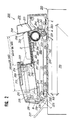
- FIG.2 is a front sectional view of a document conveyor using the paper feed device of the present invention.
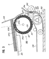
- FIG.3 is a front sectional view of the principal parts of an embodiment of the paper feed device of the present invention with a suction cylinder device.
- FIG.4 is a sectional plan view of part of the suction cylinder device shown in FIG. 3.
- FIG.5 is a perspective view of the outer cylinder member of the cylinder device.
- FIG.6 is a perspective view of an intermediate cylinder member.
- FIG.7 is a perspective view of the inner cylinder member of the cylinder device.
- FIGs.8A to 8D are sectional views for explaining the paper feed process.
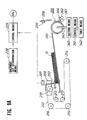
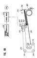
- FIG.9A and FIG.9B are views showing the structure of a recycle-type document conveying device.
- FIG.10 is a timing chart for the paper feed process.
- FIG.11 is a flow chart for the paper feed process.
- RH recycle-type document conveying device
- ADF automatic document feeder
- ADU double-sided copying device
- a recycle-type document conveying device (RDH) 200 used with a paper feed device of the present invention is mounted on a main body 100 of a copy machine.
- a paper feed unit 400 for feeding copying paper, and a copy handling device 500 for binding or punching holes in the copy on completion of the copying process are also provided.
- FIG.2 is a front sectional view of the recycle-type document conveying device 200 provided with the paper feed device of the present invention.which is installed on the main body 100 of the copy machine.
- the recycle-type document conveying device 200 is provided with a document stacker 201 in which the front section downstream in the document conveying direction is raised in the forward direction (corresponding to the paper loading tray).
- a back end regulating plate 202 for contacting the back end of the document, and a width regulating plate 203 for regulating the document D in the lateral direction when a document D is set on the document stacker 201 are also provided.
- the width regulating plate 203 is connected alternately to a pair of rack gears 205, 205 respectively which can slide in the lateral direction and between which a pinion gear 204 is interposed, and by sensing the movable position of the width regulating plate 203 by means of a sensor (omitted from the drawing), symmetrically movable around the centerline of the width of the document, the width of the document D is read out.
- the back end regulating plate 202 can press the front end of the document D which is set on the document stacker 201 as far as the sensed position (fixed position) of a document stopper 208 and a stack sensor 206.
- the document stopper 208 is positioned close to a paper feed port in the paper feed direction of the document stacker 201 and is secured to a frame member in the paper feed section.
- a blower means 280 is provided on the reverse surface of the document stopper 208. Air is blown through a bottom blower port 271 to assist in separating the documents.
- a document setting sensor 207 for sensing whether or not the document D is set on the document loading tray 201 is provided.
- the sensor 207 is installed on an upper stage transfer member 209 at the upper front part of the back end regulating plate 202, and is formed so that it can move integrally with the plate 202.
- the sensor 207 in any of the cases where the document D is halted at its original position on the document stacker 201; where the back end of the document D is pushed to slide onto the document stacker 201; and where the front end of the document D reaches the paper feed starting position, can optically sense whether or not the document D is set on the document stacker 201. When the document D is not set on the document loading tray 201, the sensor 207 can prevent a copy from entering the copying operation and being wasted.
- the document setting sensor 207 is secured to a discharge paper port guide plate on the upper stage transfer member 209 so that its front section projects forward. At the bottom surface of the front end of the frame member on which the sensor 207 is mounted, a penetrating hole is formed, and the light projected from the inside of the frame of the sensor 207, and the light reflected to the sensor 207 passes through the penetrating hole in the frame member.
- the sensor 207 is provided in the same frame as a light emitting section and a light receiving section, formed from a light emitting diode and a phototransistor respectively.
- the light beam projected from the light emitting section (LED) passes through the penetrating hole in the frame to a reflection plate 202a which projects forward and is integrally formed from the bottom edge of the back end regulating plate 202 and is integrally formed with the back end regulating plate 202.
- the beam reflected from the reflection plate 202a once again passes through the frame penetrating hole to the light receiver (phototransistor).
- the back end regulating plate 202 and the document setting sensor 207 are mounted on the upper stage transfer member 209, and in addition, a document classifying device (set separator) 210 is integrally suspended from the transfer member 209 close to its center.
- a previously positioned dividing arm (selector) 211 on the document classifying device 210 is set on the uppermost document of a stack of documents loaded onto the document stacker 201.
- the documents in the once-cycled stack are consecutively loaded onto the upper section of the dividing arm 211.
- the dividing arm 211 is removed from the document loading position, and when the final page is returned to the document loading table and is loaded in the uppermost position of the document stack, the dividing arm 211 applies pressure to the uppermost sheet of the document stack.
- an end roller 213 which is rotated by means of a paper discharge belt 212, and a follower roller 214 which rotatingly follows when pressure is applied, are axially supported on the upper stage transfer member 209.
- the paper discharge belt 212 is stretched so that the rear side of the document stacker 201 is rolled up into a C shape by means of a drive roller 215 which is connected to a main motor through a unidirectional control mechanism, an upper side end roller 213 axially supported so that it can move horizontally along the upper and lower surfaces of the document stacker 201, a lower side end roller 216, and a group of auxiliary rollers 271, 218, 219.
- a conveyor belt 220 is provided for conveying the document D in both the forward direction and the reverse direction on the top surface of the platen glass 102.
- the conveyor belt 220 is stretched between a first roller 221 connected to the main drive motor through a forward/reverse switching means, and a second roller 222 on the paper discharge side.
- a tension roller 223 applies pressure to the upper side of the belt surface from the first roller 221, and the lower side belt surface is caused to slide along the surface of the platen glass 102 by a plurality of presser rollers 224, 224, 224.
- the first roller 221 and the second roller 222 are linked together by a timing belt which has been omitted from the drawings.
- the conveyor belt 220 is operated by the driving force from the first roller 221 when it moves in the forward direction (the clockwise direction in FIG. 2), and the lower belt surface becomes the slack side. In this case, the second roller 222 slides with respect to a unidirectional clutch.. In addition, in the case where the conveyor belt 220 runs in the reverse direction (the counterclockwise direction), the unidirectional clutch becomes locked and the second roller 222 becomes the drive side of the conveyor belt 220.
- the conveyor belt 220 can be operated with the first roller 221 as the drive side, or with the second roller 222 as the drive side. This is particularly effective when the document D is running on the platen glass 102 where synchronous exposure is performed.
- a document stopper 103 is provided at the paper discharge end of the platen glass 102 and is provided with an action allowing it to protrude from or recede into the platen glass 102.
- the document stopper 103 recedes into the platen glass 102 when the document ID is being conveyed in the document recycle copy mode by the conveyor belt 220 at the synchronous exposure speed on the platen glass 102, whereby an optical exposure system 110, which can be secured at a fixed position directly under the platen glass 102 or can move, implements the exposure and forms an image on a photosensitive drum body,.
- the document In the case where, in the automatic document feeder (ADF) mode or in the semiautomatic document feeder (SDF) mode, the document is halted at the exposure position on the platen glass 102, and is exposed with the optical system 110 moving so that an image is formed on the drum, the document stopper 103 is moved so that it protrudes from the top of the platen glass 102.
- ADF automatic document feeder
- SDF semiautomatic document feeder
- a paper discharge guide plate 225 is provided which is a continuation of the discharge port side of the platen glass 102.
- a switching finger 226 is provided which switches the document between a recycle paper discharge channel B leading to the document stopper 201 and an external paper discharge channel C leading to an external paper discharge tray.227, part way along the paper discharge guide plate 225.
- the back end regulating plate 202 returns to the home position it opens the external paper discharge channel C, and when the back end regulating plate 202 is not at the home position it opens the recycle paper discharge channel B.
- a channel E is provided for reversing the document when both sides are to be copied.
- the document D is reversed in somersault fashion in the channel E, then again conveyed onto the platen glass 102.
- a suction cylinder device 300 is provided for separating the documents one at a time from the document stack, which is in a fixed position, and feeding the documents onto the platen glass 102
- FIG.3 is a front sectional view showing one embodiment of the paper feed device of the present invention with a suction cylinder device.
- FIG.4 is a sectional plan view of part of the suction cylinder device 300.
- FIG.5 is a perspective view of the outer cylinder member of the cylinder device.
- FIG.6 is a perspective view of an intermediate cylinder member.
- FIG.7 is a perspective view of an inner cylinder member of the cylinder device.
- the cylindrical device 300 comprises an outer cylinder member (first cylinder) 311, an intermediate cylinder member (second cylinder) 321, an inner cylinder member (third cylinder) 331, and a drive means for rotatingly driving the cylinder members.
- the outer cylinder member (first cylinder) 311 is made from a thin-walled cylindrical aluminum alloy pipe, one millimeter thick or less.
- a plurality of small diameter through-holes 311A perforate the outer peripheral surface of the outer cylinder member 311, and the outer peripheral surface is covered with synthetic rubber.
- the diameter of the small diameter through-holes 311A is in the 3 to 10 mm range, and the through-holes 311A are arranged in a regular grid or in a zig-zag shape.
- the intermediate cylinder member 321 is a thin-walled cylinder with a plurality of small openings formed by a nickel electroplating process or a stainless steel thin-plate etching process.
- the thin-walled cylinder in nickel by an electroforming process using the outer blade of a power shaver. If this electroforming process is used, the thin-walled cylinder with a wall thickness of 1 mm or less, for example 0.1 mm, with a plurality of small openings perforating the walls, can be constructed at low cost and with high precision, with a well-finished surface free of any burrs or damage. As an alternative, the thin-walled cylinder with a plurality of small openings can be formed as a thin-walled cylinder with a stainless steel plate surface, and the plurality of small holes formed by etching.
- the surface of the thin-walled cylinder with a plurality of small openings fabricated in this manner must have a high friction factor suitable for adsorbing and transporting the paper, therefore its surface is roughened and it is coated with synthetic resin.
- the material and the film layer of this cylinder are formed of a material with superior characteristics with respect to strength, flexible return, heat resistance, low temperature resistance, abrasion resistance, oil resistance, adhesion, and the like.
- the synthetic rubber coating on the surface of the drum is a material with a high friction factor and superior characteristics with respect to strength, heat resistance, low temperature resistance, abrasion resistance, oil resistance, adhesion, and the like.
- a material with a high friction factor and superior characteristics with respect to strength, heat resistance, low temperature resistance, abrasion resistance, oil resistance, adhesion, and the like examples include ethylene propylene rubber (EPDM), chloroprene rubber, urethane rubber, styrene rubber, acrylic rubber, butyl rubber, butadiene rubber, silicone rubber, fluorine rubber, and the like, formed as a uniform coating by painting or spraying.
- a pair of flanges 312, 313 are integrally fitted, one at each end of the outer cylinder member 311, corresponding to the inner diameters of the openings.
- a bearing BR1 is securely fitted into the flange 312 corresponding to the inner diameter of the opening of the flange 312.
- the bearing BR1 is linked to a suction tube 314 which is mounted on a side plate 301 and supported in a freely rotatable manner on the outer wall of a suction connection tube 315 which is fitted into the bearing BR1.
- the suction tube 314 is connected to a suction means, for example, a suction pump 340, through a suction tube 343, and provides air to the triple-cylinder assembly 311, 321, 331 of the suction cylinder device 300.
- a suction means for example, a suction pump 340
- the suction pressure in the suction means 340 can be varied by a control means 341, through, for example, a range from a minimum of 200 mm Hg to 400 mm Hg, in stages or continuously.
- the suction pressure is raised and lowered corresponding to a predetermined time set by the control means 341 or by a timer means 342.
- a gear 312G is integrally formed on a section at the external diameter of the flange 312.
- the rotation of a pinion gear G11 which is driven by a motor M1, causes a gear G12 on a first countershaft 302 and a toothed pulley P11 to rotate.
- the rotation of the pinion gear G11 causes a gear G13 and a toothed pulley P12 connected to a clutch K on a second countershaft 303 to rotate via a toothed belt B1, and also causes the rotation of the gear 312 G secured to one end of the outer cylinder member 311, engagingly driven by the gear G13.
- the toothed belt B1 causes a pair of intermediate conveyor rollers 261, 262 to rotate via a third countershaft (omitted from the drawings, but identical in shape to the second countershaft) (see FIG.4).
- a guide plate 263 and a document front end sensor 264 are also provided.
- a bearing BR2 is securely fitted onto a section at the outer diameter of the boss of the flange 313 on the other end of the outer cylinder member 311, and the bearing BR2 is fitted into and supported by a support member 316 which is mounted on a side plate 304. Accordingly, both ends of the outer cylinder member 311 are supported in a freely rotatable manner on the side plates 301, 304. Then, one document at a time is intimately held against the cylindrical surface of the outer cylinder member 311 by suction from the small diameter through-holes 311A, without conveying, and the drive rotation is stopped.
- the intermediate cylinder member (second cylinder) 321 is formed, for example, from a thin-walled cylindrical aluminum alloy pipe.
- a pair of rectangular main suction ports 321A with a large open area, and six rectangular secondary suction ports 321B with a small open area are formed.
- the angle of the openings of the main suction ports 321A is set at 15° to 30°, while the angle of the openings of the secondary suction ports 321B is set at 5° to 15°.
- the intermediate cylinder member 321 can also be fabricated in cylinder form using a hardened resin process, or as a cylinder made from a paper tube covered withn resin.
- the spacing g between the outer peripheral wall of the cylindrical surface of the intermediate cylinder member 321 and the inner peripheral wall of the cylindrical surface of the outer cylinder member 311 is set and maintained at 1 mm or less, and preferably 0.7 mm or less.
- the outer cylinder member 311 is fabricated as a thin-walled cylinder and can be flexibly deformed, when a localized loading is applied to the outer cylinder member 311 causing deformation, the spacing g between the intermediate cylinder member 321 and the outer cylinder member 311 becomes smaller, and the thick wall of the intermediate cylinder member 321, which has rigidity, backs up and resists the deformation of the outer cylinder member 311. Both cylinder members are supported in a slideable manner, so that no permanent distortion is produced in the outer cylinder member 311 and when the external stress is removed it returns elastically to its original shape. Furthermore, as the spacing g decreases, the air suction efficiency from the ports 321A, 321B increases, and the paper adsorption performance improves. Specifically, the air leaking from the spacing g is minimized.
- the flanges 322,323 are fitted into the two open ends of the intermediate cylinder member 321 and integrally secured.
- the bearing BR3 is securely fitted into the inner diameter section of the flange 322, against the outer peripheral surface of the suction connecting tube 315 and supported in a freely rotational manner.
- a bearing BR4 is securely fitted onto a section at the outer diameter of the boss of the flange 313, and the flange 323 is supported in a freely rotatable manner on the flange 313 by engaging the flange 313 through the bearing BR4.
- a toothed pulley P22 and a cam plate 324 are secured near the front end of the boss section of the flange 323.
- the drive rotation of a pinion gear G21 from the motor M2 causes through a gear G22 loosely fitted on the first countershaft 305, a gear G23 loosely fitted on a second countershaft 306, and a toothed pulley P21 to rotate, thus causing the toothed belt P22 to rotate via a toothed belt B2.
- the cam plate 324 controls the rotation of the intermediate cylinder member 321 by opening and closing the optical path of the photointerrupter (transparent optical coupling element) 325.
- the intermediate cylinder member 321 operates a shutter which applies suction and separates the documents by means of the suction from the main suction port 321A and the secondary suction ports 321B of the intermediate cylinder member 321, and halts the driving rotation. Therefore, for every rotation one document is conveyed and the rotation is halted.
- the inner cylinder member (third cylinder) 331 is formed, for example, from a thin-walled cylindrical aluminum alloy pipe.
- Two rectangular suction ports 331A, 331A are formed on one part of the external peripheral surface.
- the open angle of the suction ports 331A is set at 30° to 60°.
- Two flanges 332, 333 are fitted into the two open ends of the inner cylinder member 331 respectively and integrally secured.
- the flange 332 is supported in a freely rotational manner against the outer peripheral surface of a suction connecting tube 336, through a bearing BR5 in the same manner as the flange 322.
- the boss of the flange 333 is supported in a freely rotational manner on the flange 323, through a bearing BR6, and a fixed shaft 334 is secured to the boss of the flange 333.
- the fixed bearing 334 is loosely inserted into the boss of the flange 323, and the projecting right end of the bearing 334 is secured to a support plate 335 which is in turn secured to the side plate 304.
- the front and back ends of the document D1 which has been discharged onto the document stacker 201 are aligned by the document stopper 208 and the back end regulating plate 202.
- the document is once again stacked with the width aligned by the width regulating plates 203, 203.
- the documents D, which have been stacked previously, and the recycled documents D1 are classified by means of the document classifying device 210. This forwarding operation is repeated until there are no more documents D left on the document stacker 201.
- the fact that no more documents D remain is detected by the stack sensor 206, and when the forwarding of the last document D is detected by the paper discharge sensor, the abovementioned action is repeated until the set number of copies of the documents has been forwarded from the stacked documents at the back end regulating plate 202.
- the back end regulating plate 202 returns to the home position and is prepared for the next operation.
- the above operation has been described for the case where single-sided copies are made of a single-sided document in RDH mode.
- the documents are introduced into the channel E where they are reversed in somersault fashion.
- the inner cylinder member 331 is fixed and the intermediate cylinder member 321 is drivenly rotated, but the present invention is not restricted to this embodiment.
- the intermediate cylinder member 321 may remain fixed and the inner cylinder member 331 may be drivenly rotated, or the bottom paper in the stack may be separated by suction while the relative openings formed by the slotted openings in both cylinder members are being switched from a closed state to a gradually opening state.
- the paper feed device of the present invention effectively applies the document bottom feed method for the document conveying device, but in addition to this it is also possible to apply this to a paper feed device in which the paper is fed from the bottom of the stack.
- the paper feed device of the present invention forwards a stack of papers loaded on a document stacker in the feed direction, and separates the papers from the stack one at a time from the bottom using a separating means. Forwarding of the papers and separating and feeding is performed in a stable manner by means of a suction cylinder device comprising a triple-cylinder mechanism and a suction means, so that it is not necessary to apply pressure to the stacked papers.
- a suction cylinder device comprising a triple-cylinder mechanism and a suction means
- the suction cylinder device with the triple-cylinder mechanism of the present invention can convey sheets of light paper (tracing paper or the equivalent of 40 to 45 kg paper) by suction at a negative pressure (about 200 mm Hg) and also convey relatively heavy paper (the equivalent of 70 to 110 kg paper) by automatic regulation of the suction pressure to provide the optimum suction pressure for the type of paper. For this reason the paper separating performance is improved and separating and conveying can be reliably carried out regardless of the paper size and weight.
- suction can be produced over the entire surface so that a uniform suction is applied to the surface of the paper for conveying. Therefore, double conveying, and the production of creases in the paper or bending of the corners can be eliminated, and a stable conveying operation can be provided.
Landscapes
- Engineering & Computer Science (AREA)
- Mechanical Engineering (AREA)
- Sheets, Magazines, And Separation Thereof (AREA)
Applications Claiming Priority (6)
| Application Number | Priority Date | Filing Date | Title |
|---|---|---|---|
| JP2102732A JP2779687B2 (ja) | 1990-04-18 | 1990-04-18 | 給紙装置 |
| JP102734/90 | 1990-04-18 | ||
| JP102732/90 | 1990-04-18 | ||
| JP2102733A JPH043738A (ja) | 1990-04-18 | 1990-04-18 | 給紙装置 |
| JP102733/90 | 1990-04-18 | ||
| JP2102734A JP2934976B2 (ja) | 1990-04-18 | 1990-04-18 | 給紙装置 |
Publications (1)
| Publication Number | Publication Date |
|---|---|
| EP0452911A1 true EP0452911A1 (de) | 1991-10-23 |
Family
ID=27309783
Family Applications (1)
| Application Number | Title | Priority Date | Filing Date |
|---|---|---|---|
| EP91106162A Withdrawn EP0452911A1 (de) | 1990-04-18 | 1991-04-17 | Blattzuführvorrichtung |
Country Status (2)
| Country | Link |
|---|---|
| US (1) | US5213320A (de) |
| EP (1) | EP0452911A1 (de) |
Cited By (8)
| Publication number | Priority date | Publication date | Assignee | Title |
|---|---|---|---|---|
| DE4416743A1 (de) * | 1994-05-12 | 1995-11-16 | Frank Gruetzmacher | Beilagenstation für eine Kuvertiermaschine |
| EP0939046A1 (de) * | 1998-02-25 | 1999-09-01 | Karl Dr. Ritsert | Vorrichtung und Verfahren zur Datenerfassung |
| EP0959030A1 (de) * | 1998-05-13 | 1999-11-24 | Gunther De Beleyr | Vorrichtung zum Zuführen von dünnen Gegenständen zu einer Transporteinrichtung in geschuppter Formation |
| EP1095885A3 (de) * | 1999-10-26 | 2001-08-01 | Giesecke & Devrient GmbH | Vorrichtung zum Vereinzeln von flachem Fördergut mit einer Saugeinrichtung |
| WO2003016072A1 (fr) * | 2001-08-13 | 2003-02-27 | Assy S.A. | Dispositif automatique pour tourner les pages d'un document relie |
| WO2006089749A1 (de) * | 2005-02-25 | 2006-08-31 | Giesecke & Devrient Gmbh | Vorrichtung für die vereinzelung von banknoten |
| DE102007040610B3 (de) * | 2007-08-27 | 2009-07-23 | Ten-Sheeg Machinery Co. Ltd. | Transportradgerät für eine Schneideeinrichtung |
| CN114222709A (zh) * | 2019-08-16 | 2022-03-22 | 富士胶片商业创新有限公司 | 纸张传送装置及图像形成装置 |
Families Citing this family (8)
| Publication number | Priority date | Publication date | Assignee | Title |
|---|---|---|---|---|
| US5508823A (en) * | 1991-08-28 | 1996-04-16 | Canon Kabushiki Kaisha | Image processing method and apparatus |
| JP3337720B2 (ja) * | 1991-10-15 | 2002-10-21 | キヤノン株式会社 | シート搬送装置 |
| US5552859A (en) * | 1994-02-08 | 1996-09-03 | Canon Kabushiki Kaisha | Sheet supplying apparatus with means for rocking sheet stacking plate |
| JP3207711B2 (ja) * | 1995-05-08 | 2001-09-10 | シャープ株式会社 | エアー給紙装置 |
| US6015146A (en) * | 1998-01-08 | 2000-01-18 | Xerox Corporation | Curl sensitive bottom vacuum corrugation feeder |
| EP1403199B1 (de) * | 2002-09-27 | 2006-11-02 | Eastman Kodak Company | Bogenzuführvorrichtung für eine bogenverarbeitende Maschine |
| JP5400101B2 (ja) * | 2011-07-27 | 2014-01-29 | 富士フイルム株式会社 | 媒体搬送装置及び画像形成装置 |
| US8544837B2 (en) * | 2011-12-30 | 2013-10-01 | Pitney Bowes Inc. | Vacuum roller assembly |
Citations (3)
| Publication number | Priority date | Publication date | Assignee | Title |
|---|---|---|---|---|
| GB240785A (en) * | 1924-10-04 | 1926-06-25 | Lawrence Carr Steele | Improvements in apparatus for conveying sheets and plates to machines from a pack resting on edge |
| GB685810A (en) * | 1951-01-25 | 1953-01-14 | Douglas Hamilton Pope | Improved apparatus for sequentially feeding individual sheets of paper or the like |
| EP0413471A2 (de) * | 1989-08-12 | 1991-02-20 | Konica Corporation | Papier-Zuführungsvorrichtung |
Family Cites Families (7)
| Publication number | Priority date | Publication date | Assignee | Title |
|---|---|---|---|---|
| GB2068904B (en) * | 1978-02-07 | 1983-01-26 | Edstrom L G | Sheet separating and mechanism |
| US4324395A (en) * | 1979-10-03 | 1982-04-13 | Xerox Corporation | Sheet separator |
| US4284270A (en) * | 1979-10-03 | 1981-08-18 | Xerox Corporation | Stack for bottom sheet feeder |
| US4345751A (en) * | 1980-07-25 | 1982-08-24 | Eastman Kodak Company | Sheet feeding apparatus |
| US4411417A (en) * | 1981-11-02 | 1983-10-25 | Xerox Corporation | Bottom sheet feeding apparatus |
| US4585222A (en) * | 1982-03-01 | 1986-04-29 | Sharp Kabushiki Kaisha | Sheet paper attracting system |
| US4662622A (en) * | 1984-07-18 | 1987-05-05 | Tektronix, Inc. | Air density adaptive vacuum controller |
-
1991
- 1991-04-17 US US07/686,480 patent/US5213320A/en not_active Expired - Fee Related
- 1991-04-17 EP EP91106162A patent/EP0452911A1/de not_active Withdrawn
Patent Citations (3)
| Publication number | Priority date | Publication date | Assignee | Title |
|---|---|---|---|---|
| GB240785A (en) * | 1924-10-04 | 1926-06-25 | Lawrence Carr Steele | Improvements in apparatus for conveying sheets and plates to machines from a pack resting on edge |
| GB685810A (en) * | 1951-01-25 | 1953-01-14 | Douglas Hamilton Pope | Improved apparatus for sequentially feeding individual sheets of paper or the like |
| EP0413471A2 (de) * | 1989-08-12 | 1991-02-20 | Konica Corporation | Papier-Zuführungsvorrichtung |
Cited By (10)
| Publication number | Priority date | Publication date | Assignee | Title |
|---|---|---|---|---|
| DE4416743A1 (de) * | 1994-05-12 | 1995-11-16 | Frank Gruetzmacher | Beilagenstation für eine Kuvertiermaschine |
| EP0939046A1 (de) * | 1998-02-25 | 1999-09-01 | Karl Dr. Ritsert | Vorrichtung und Verfahren zur Datenerfassung |
| EP0959030A1 (de) * | 1998-05-13 | 1999-11-24 | Gunther De Beleyr | Vorrichtung zum Zuführen von dünnen Gegenständen zu einer Transporteinrichtung in geschuppter Formation |
| EP1095885A3 (de) * | 1999-10-26 | 2001-08-01 | Giesecke & Devrient GmbH | Vorrichtung zum Vereinzeln von flachem Fördergut mit einer Saugeinrichtung |
| WO2003016072A1 (fr) * | 2001-08-13 | 2003-02-27 | Assy S.A. | Dispositif automatique pour tourner les pages d'un document relie |
| US7430035B2 (en) | 2001-08-13 | 2008-09-30 | Assy S.A. | Automatic device for turning the pages of a bound document |
| WO2006089749A1 (de) * | 2005-02-25 | 2006-08-31 | Giesecke & Devrient Gmbh | Vorrichtung für die vereinzelung von banknoten |
| DE102007040610B3 (de) * | 2007-08-27 | 2009-07-23 | Ten-Sheeg Machinery Co. Ltd. | Transportradgerät für eine Schneideeinrichtung |
| CN114222709A (zh) * | 2019-08-16 | 2022-03-22 | 富士胶片商业创新有限公司 | 纸张传送装置及图像形成装置 |
| CN114222709B (zh) * | 2019-08-16 | 2024-04-05 | 富士胶片商业创新有限公司 | 纸张传送装置及图像形成装置 |
Also Published As
| Publication number | Publication date |
|---|---|
| US5213320A (en) | 1993-05-25 |
Similar Documents
| Publication | Publication Date | Title |
|---|---|---|
| US5213320A (en) | Paper feed device | |
| US5088717A (en) | Paper feeding apparatus having a three cylinder vacuum member | |
| US4469319A (en) | Large document restacking system | |
| US7828281B2 (en) | Sheet post-processing apparatus and sheet post-processing method | |
| JP2651602B2 (ja) | 給紙装置 | |
| US4957285A (en) | Document feeder with sheet edge regulating mechanism | |
| US10042305B2 (en) | Sheet processing device and sheet processing method | |
| US20120267845A1 (en) | Sheet stacking device and method of stacking sheets | |
| US12485660B2 (en) | Sheet separation device, sheet laminator, image forming apparatus, and image forming system | |
| US6394447B1 (en) | Sheet inversion device | |
| JPH0615391B2 (ja) | シ−ト整合装置 | |
| JP2549071B2 (ja) | シート整合装置 | |
| JP2779687B2 (ja) | 給紙装置 | |
| GB2123524A (en) | Rollers | |
| JP2652710B2 (ja) | 給紙装置 | |
| JP4545251B2 (ja) | シート処理装置とこのシート処理装置を備える画像形成装置 | |
| US20250162827A1 (en) | Sheet separation device, sheet laminator, and image forming system | |
| JP3208675B2 (ja) | 給紙装置 | |
| JPH043738A (ja) | 給紙装置 | |
| JP2934976B2 (ja) | 給紙装置 | |
| JP2790889B2 (ja) | ソーター綴じ装置 | |
| JPH0379525A (ja) | 給紙装置 | |
| JPH0383735A (ja) | 給紙装置 | |
| JPH0383733A (ja) | 給紙装置 | |
| JP2024152604A (ja) | シート処理装置、ラミネート処理装置、画像形成装置及び画像形成システム |
Legal Events
| Date | Code | Title | Description |
|---|---|---|---|
| PUAI | Public reference made under article 153(3) epc to a published international application that has entered the european phase |
Free format text: ORIGINAL CODE: 0009012 |
|
| AK | Designated contracting states |
Kind code of ref document: A1 Designated state(s): DE FR GB |
|
| 17P | Request for examination filed |
Effective date: 19920414 |
|
| 17Q | First examination report despatched |
Effective date: 19931213 |
|
| STAA | Information on the status of an ep patent application or granted ep patent |
Free format text: STATUS: THE APPLICATION IS DEEMED TO BE WITHDRAWN |
|
| 18D | Application deemed to be withdrawn |
Effective date: 19940426 |