EP0452928B1 - Gerät zur Aufzeichnung von Bildern mehrerer Gradationen - Google Patents
Gerät zur Aufzeichnung von Bildern mehrerer Gradationen Download PDFInfo
- Publication number
- EP0452928B1 EP0452928B1 EP91106221A EP91106221A EP0452928B1 EP 0452928 B1 EP0452928 B1 EP 0452928B1 EP 91106221 A EP91106221 A EP 91106221A EP 91106221 A EP91106221 A EP 91106221A EP 0452928 B1 EP0452928 B1 EP 0452928B1
- Authority
- EP
- European Patent Office
- Prior art keywords
- recording
- gradation
- signal
- level
- correction
- Prior art date
- Legal status (The legal status is an assumption and is not a legal conclusion. Google has not performed a legal analysis and makes no representation as to the accuracy of the status listed.)
- Expired - Lifetime
Links
Images


Classifications
-
- H—ELECTRICITY
- H04—ELECTRIC COMMUNICATION TECHNIQUE
- H04N—PICTORIAL COMMUNICATION, e.g. TELEVISION
- H04N1/00—Scanning, transmission or reproduction of documents or the like, e.g. facsimile transmission; Details thereof
- H04N1/40—Picture signal circuits
- H04N1/401—Compensating positionally unequal response of the pick-up or reproducing head
- H04N1/4015—Compensating positionally unequal response of the pick-up or reproducing head of the reproducing head
-
- H—ELECTRICITY
- H04—ELECTRIC COMMUNICATION TECHNIQUE
- H04N—PICTORIAL COMMUNICATION, e.g. TELEVISION
- H04N1/00—Scanning, transmission or reproduction of documents or the like, e.g. facsimile transmission; Details thereof
- H04N1/40—Picture signal circuits
-
- H—ELECTRICITY
- H04—ELECTRIC COMMUNICATION TECHNIQUE
- H04N—PICTORIAL COMMUNICATION, e.g. TELEVISION
- H04N1/00—Scanning, transmission or reproduction of documents or the like, e.g. facsimile transmission; Details thereof
- H04N1/40—Picture signal circuits
- H04N1/405—Halftoning, i.e. converting the picture signal of a continuous-tone original into a corresponding signal showing only two levels
- H04N1/4055—Halftoning, i.e. converting the picture signal of a continuous-tone original into a corresponding signal showing only two levels producing a clustered dots or a size modulated halftone pattern
- H04N1/4057—Halftoning, i.e. converting the picture signal of a continuous-tone original into a corresponding signal showing only two levels producing a clustered dots or a size modulated halftone pattern the pattern being a mixture of differently sized sub-patterns, e.g. spots having only a few different diameters
Definitions
- the invention relates to a multi-gradation image recording apparatus to be applied to such recording apparatuses as printers, copying machines, and facsimile machines, and more particularly to a recording apparatus capable of producing high-quality multi-gradation images.
- thermosensitive recording apparatus and a thermal transfer recording apparatus, being relatively simple in their structure, are extensively applied to various recording systems such as printers, copying machines, and facsimile machines.
- a thermal transfer recording method using, e.g., sublimated ink sheets is employed.
- an amount of color ink which corresponds to an amount of heat generated by electric energy applied to a plurality of heating resistors constituting a recording thermal head, is transferred onto a recording sheet to record the images.
- the amount of heat generated by the heating resistors is controlled by the number and duration of electric pulses applied to these resistors.
- This thermal transfer recording method allows comparatively satisfactory multi-gradation recording to be achieved with a simple control.
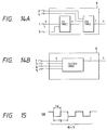
- FIG. 15 is a chart showing waveforms of conducting pulse SB to be applied to the respective heating resistors constituting the thermal head in this conventional multi-gradation recording system, where t w is the pulse duration of the conducting pulse SB, t p is the repetitive cycle of the conducting pulse SB, and N is the number of conducting pulses SB (3 in this example).
- the number of conducting pulses SB is selected and set in advance on a density basis, each density being expressed in a gradation level.
- the conducting pulses SB are applied to the corresponding heating resistors arranged in line on the thermal head either collectively or in division.
- the recording of a plurality of lines is performed while forwarding a recording sheet in an auxiliary scanning direction at a constant speed sequentially.
- the multi-gradation recording is performed as described above. Since a major factor defining the recording density of each gradation level is the temperature of each heating resistor disposed on the thermal head, variations in resistance of the heating resistors and variations in temperature due to change in ambient temperature or the like greatly affect the recording density, and this makes it difficult to implement high-quality recording. To overcome such a shortcoming, various correction means have been proposed.
- a thermistor temperature-sensitive element
- the thermistor mounted on the thermal head detects changes in temperature so that the duration or number of pulses specified every gradation level are controlled. Therefore, the variations in the recording density of the same gradation level can be suppressed.
- Figure 16 is a block diagram showing a means for correcting erratic resistances.
- reference numeral 101 designates a counter for counting a clock
- 102 an EPROM (erasable programmable read only memory) which receives count data from the counter 101 as an address and outputs data (a correction constant number specified for each heating resistor) for the address
- Its operation comprises the steps of measuring the resistances of respective heating resistors in advance, grouping the heating resistors by the resistance, causing the EPROM 102 to store data concerning which heating resistor selects which correction constant as a number table by the counter 101, and converting the magnitude of the C, M, Y signals at the EPROM 103 that references to each group number of a correction constant. More specifically, an output signal selected from 0 to 63 levels is generated from an input signal indicating any of 0 to 63 levels in accordance with an error in the resistance of a heating resistor. For example, a 38-level signal corresponding to a 100th heating resistor is recorded after being corrected to a 40-level or 35-level signal.
- the conventional multi-gradation recording apparatus is disadvantageous as follow.
- the conventional multi-gradation recording system could not correct density nonuniformity at a high-density portion. For example, even if an input signal has 64 gradation levels, the recorded images are compressed to 50 gradations. Therefore, high-quality recording, such as photograph, could not be achieved.
- the density nonuniformity correction means receives no signal corresponding to a color signal.
- recording color-based density nonuniformity cannot be corrected completely and thus high-quality recording comparable to photographs cannot be implemented.
- a relation between the energy to be applied to the thermal head (the number of conducting pulses) per color and the recording density cannot be expressed as a linear function since the low and high density portions have gradual inclinations.
- a recording density is segmented uniformly.
- the number of pulses are defined in advance in such a manner that: level 1 is set to 10 pulses; level 2, to 16 pulses; ...
- Each image element comprises a number of cells, and in each cell a dot is formed.
- Each dot for each colour has assigned at least two densities. If there is more than one possibility to represent the same density in the image cell, a constellation is chosen which provides the larger number of dot cells in the image cell.
- an object of the invention is to provide a multi-gradation recording apparatus whose circuits are simplified by reducing the number of recording gradation level bits specified to each recording element without reducing the recording resolution and whose idle time in which no recording is performed to the thermal head is shortened to increase its recording speed.
- a multi-gradation recording apparatus for producing high quality multi-gradation images, comprising: recording means for recording the multi-gradation images, said recording means having a plurality of recording elements; correction means for correcting an input gradation signal having a predetermined first number of gradation levels in response to correction data with reference to a first data table in order to compensate differences of the characteristics of each of said recording elements, said first data table representing a correspondence among the input gradation signal and a corrected gradation signal having a second number of gradation levels, the second number being larger than the first number; and pulse count generating means for applying drive pulse signals to said recording means based on the output signal of said correction means.
- a first aspect of the invention is applied to a multi-gradation recording apparatus, which includes correction means for density nonuniformity.
- This correction means is effective also to a high-density portion which includes greater part of gradation levels in the scale of n gradation levels, and corrects an n-level input to an (n + m)-level output so that recording of the pixels can be effected at an (n + m) level.
- a second aspect of the invention is applied to a multi-gradation recording apparatus which corrects an n-level input to an (n + m)-level output to correct density nonuniformity caused by erratic recording element outputs or the like, and such (n + m) level is combined with position data of k pixels to provide the recording elements corresponding to the k pixels with a set of coarse gradation levels which are substantially (n + m)/l, so that the k pixels are recorded by the corresponding k recording elements at the coarse gradation levels.
- a third aspect of the invention is applied to a multi-gradation recording apparatus which provides a recording element of recording means with a drive count proportional to an input gradation level by allowing a maximum drive count to be set variably so that, when the recording means is replaced and, as a result, an input signal indicating a maximum gradation level is changed, a maximum drive count of the replaced recording means can be accommodated.
- a fourth aspect of the invention is applied to a multi-gradation recording apparatus which applies color signals indicating such recording colors as Y, M, and C, or Y, M, C, and Bk to correction means 2 or correction data storage means 12, so that an output signal can be corrected by the color.
- the multi-gradation recording apparatus not only allows the number of bits of an (n + m) level signal, which is a corrected output, to be larger than the number of bits of an input signal so that gradation levels at a high-density side can also be corrected properly.
- the multi-gradation recording apparatus additionally uses position data of a plurality of pixels and provides recording elements with gradation level signals, each of which consists of such a reduced number of bits as corresponding to a maximum (n + m)/l gradation level even with respect to an (n + m)-level input signal whose number of bits has become larger than that of an original input signal by density nonuniformity correction.
- the multi-gradation recording apparatus defines the maximum drive count for driving the recording elements in accordance with a maximum gradation level input.
- the multi-gradation recording apparatus defines the output of the correction means 2 or the correction data storage means 12 based on a color signal.
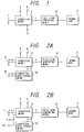
- Figure 1 is a block diagram showing a multi-gradation recording apparatus, which is an embodiment of the invention
- Figures 2A and 2B are block diagrams showing multi-gradation recording apparatuses, which are embodiments of a fourth aspect of the invention
- Figures 3A to 3D and Figure 4 are diagrams for a description of the fourth aspect of the invention
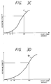
- Figure 5 is a diagram showing a correlation between the conducting pulse count and the recording density
- Figure 6 is a diagram showing a correlation between the corrected gradation level and the recording density
- Figure 7 is a diagram showing a table for preparing an output corrected gradation level from both a correction data of a recording element and an input gradation level
- Figure 8 is a diagram showing a correlation between the input signal and the corrected signal
- Figures 9A to 9C are diagrams for a description of the construction and density of pixels
- Figures 10A and 10B are diagrams for a description of a table which produces a converted gradation level output in which gradation levels of four pixels are reduced from
- a new correspondence table is prepared while reviewing changes in gradation level caused by the correction means 2.
- the new correspondence table allows, e.g., multi-gradation recording based on about 280 gradation levels out of its original multi-gradation recording based on 256 gradation levels.
- reference numeral 1 designates an input terminal to which an 8-bit gradation level signal S is applied; and 2, correction means for correcting differences in amount of heat due to, e.g., variations in the resistance of heating resistors disposed on the thermal head 7 or a like cause.
- the correction means 2 produces a correction signal h by changing an input signal S in accordance with the variations or the like as shown in Figure 7.
- reference numeral 3 designates recording line data, and 4, recording pixel position data.
- the recording line data 3 and the recording pixel position data 4 are not used in the first aspect of the invention.
- the correction signal h output from the correction means 2 is larger than input signal S.
- the correction means 2 for correcting nonuniformity of the density according to the first aspect of the invention produces and outputs an (n + m)-level correction data h (e.g., 281 gradation levels in this embodiment) relative to an n-level input gradation level signal (e.g., 256 gradation levels in this embodiment) (S ⁇ h). Accordingly, the density nonuniformity at the high-density portion can be corrected, thereby allowing a generally high-quality image to be recorded.
- the number of bits changes before and after the correction specifically, from 8 bits to 9 bits, and such an increase in the number of bits aimed at image quality improvement causes the problems of not only complicating circuits but also reducing the recording speed.
- the complicating of the circuit is caused by that the storage means, such as a ROM, for processing based on 8-bit signal and the ICs, such as counter, constructed based on 2 n unit require a circuit whose capacity is twice its present capacity, when the output signal increase only 1 bit from 8 bits to 9 bits.
- the reducing of the recording speed is caused by that the recording time period for one line becomes long due to increasing the number of the recording gradation.
- a normal 8-bit 256-gradation signal is corrected to, e.g., a 9-bit 281-gradation signal by the correction means 2 according to the first aspect of the invention.
- level 0 corresponds to density 0
- level 280 corresponds to density 1.
- level 0 corresponds to density 0
- level 70 corresponds to density 1, which results in a coarse density resolution.
- each pixel is expressed in a 281-level fine gradation scale between white and the maximum density in Figure 9A
- each of four pixels is expressed in a 71-level coarse gradation scale between the same white and maximum density in Figure 9B.
- the second aspect of the invention attempts to replace a high density gradation with a coarse gradation with these four pixels as a group. If each of the four pixels is level 1 in Figure 9A, then it is assumed that only a first odd pixel in an odd line has level 1 and that other pixels have level 0 in Figure 9B. This rule will be shown in detail in Figure 10A. As shown in Figure 9C, let it be assumed that the four pixels before conversion are 272, 277, 278, 280. In such a case, they are expressed in terms of post-conversion coarse gradation as 68, 69, 69, 70.
- This second aspect of the invention applies an integrating capacity to human vision, i.e., the capacity of seeing things as a group. More specifically, although a single pixel shown in Figure 9A is usually laid out in a group of 6 to 12 within 1 mm, human eyes can only identify 3 to 4 pixels within 1 mm. Thus, the grouping of four pixels as shown in Figure 9B does not affect image quality seen by the human eyes. It has been verified by experiments that a density variation in the gradation scale of Figure 9B, in which four pixels are grouped and a set of gradation levels is assigned to every group of four pixels, can visually be identified as being similar to a gradual density variation shown by pixels in the gradation scale of Figure 9A.
- FIG. 10A A system for achieving a high-quality image with a small number of bits by grouping a plurality of pixels will be described specifically with reference to Figures 10A and 10B.
- the positions of a plurality of k pixels are expressed by combination of an odd pixel (position A), an even pixel (position B), an odd line (position C), and an even line (position D).
- positions A, B, C, D must be expressed in the fine gradation scale of 281 levels
- the coarse gradation scale of 0 to 70 levels is specified based on the correspondence table shown in Figure 10B.
- Figures 11A to 11C are signal diagrams for a description of this second aspect of the invention.
- the correction means 2 shown in Figure 1 includes the tables shown in Figures 7 and 10B, and selected signals shown in Figures 11A and 11B are applied to the correction means 2 to specify the positions of a plurality of pixels.
- Correction data shown in Figure 11C which shows thermal head variations is also supplied to the correction means 2.
- the correction means 2 receives an input signal S, recording line data 3, recording pixel data 4, correction data 5 as described above, and a correction signal h which is smaller than the input signal S can be obtained as its output based on the tables shown in Figures 7 and 10B.
- the recording means 6, upon reception of such a correction signal h as an input, outputs a pulse count corresponding to each gradation level and controls the thermal head 7.
- the recording means 6 can record a maximum gradation level generated by the correction means 2 so that the 256-gradation level recording can be ensured properly.
- the recording means 6 applies, e.g., a maximum of 70 conducting pulses, which is in correspondence with the 70-level gradation scale, to the thermal head 7.
- the correction signal output from the correction means 2 becomes seven bits signal.
- FIG. 12A An exemplary circuit of the pulse count generating means 6 which applies drive signals j to the thermal head 7 in Figure 1 as well as a conducting pulse signal as its output are shown in Figures 12A and 12B.
- reference numeral 8 designates a recording control circuit, which transfers thermal head data and controls the conducting pulse count.
- Reference numeral 9 designates a maximum drive count setting circuit, which receives such a number of drive pulses as set by a set value signal 10 instructed by a microprocessor or the like. When the number of received pulses exceeds the set value, the maximum drive count setting circuit 9 is reset and starts counting the pulse for a next recording element of the thermal head 7.
- a value of "71” is input as a set value signal 10 and this value "71" is set to the maximum drive count setting circuit 9.
- the set value signal 10 remains fixed at level "71" in the conventional example, leaving the set value of the maximum drive count setting circuit as "71".
- an idle time equal to 5 pulse durations is produced during application of pulses to every recording element as shown in Figure 12B.
- the third aspect of the invention attempts to make the maximum drive count set by the maximum drive count setting circuit 9 of the pulse generating means 6 variable by changing the set value signal 10.
- the value set by the maximum drive count setting circuit 9 is also changed to "65", so that, as shown in Figure 12B, the conducting pulse control time to each recording element can be shortened compared with that in the conventional example.
- the fourth aspect of the invention attempts to convert an output signal on a color basis by adding a color signal 11 to the input of the correction means 2 or of the correction data storage means 12 as shown in Figures 2A and 2B.
- the color signal 11 consists of, e.g., 2 bits. Such binary inputs as “0" indicating a gradation level signal for Y; "01” indicating a gradation level signal for M; "10” indicating a gradation level signal for C; and "11” indicating a gradation level signal for Bk, if necessary, are input.
- the content of the color signal 11 is set by a not shown device control section or the like.
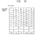
- a case in which the color signal 11 is input to the correction data storage means 12 as shown in Figure 2A indicates a method of preparing a correction constant corresponding to each heating resistor of the thermal head 7 considering energy which is different among colors as shown in Figure 13.
- a case in which the color signal 11 is inputted to the correction means 2 as shown in Figure 2B indicates a method of converting an output signal on a color basis in correspondence with a correction constant.
- a table similar to that shown in Figure 7 is prepared for each recording color.
- the table values in both cases shown in Figures 2A and 2B can be defined by calculating data such as resistance measurements and a relation between the color-specific gradation level and the recording density or by reading a recorded sample of each color with a reading device.
- the number of bits in the input signal, the number of bits in the corrected signal are not limited to the above-described values, but may be any value as long as the relationship S ⁇ h is satisfied.
- thermal transfer recording is taken as an example in the above embodiments
- the system according to the invention may similarly be applied to any recording system such as a xerographic system, a thermal recording system, or an ink jet recording system, providing the same effects as the above embodiments.
- the correction means 2 internally processes the data in the order of the first table shown in Figure 7 and the second table shown in Figure 10B in the embodiments of the second aspect of the invention.
- the same effects as those in the above embodiments may be obtained as long as the correction signal h is smaller than the input signal S.
- the tables used in the above embodiments may be replaced by microprocessor operations, which allows the same effects to be provided.
- the number of pixels is not limited to 4, but may be an arbitrary value such as 6, 8, 16, or the like.
- the numbers of bits constituting the recording line data 3 and the recording pixel position data 4 inputted to the correction means 2 are also changed, and if six pixels are taken as a group, the recording line data 3 may consist of 2 bits and the recording pixel position data 4 may consist of 1 bit or vice versa. If only two pixels are taken as a group, either the recording line data 3 or the recording pixel position data 4 may be applied to the correction means 2. In either case, no limits are imposed on the number of bits.
- the set value signal 10 is instructed from the microprocessor or the like in the third aspect of the invention, such instruction may also originate from an operation panel or the like.
- the application of the invention is not limited thereto.
- the invention may be modified in many ways as the case may require.
- the maximum drive count setting circuit 9 may be made of a counter or the like. In such a case, the number of gradation levels per line may be limited by incrementing or decrementing the set value signal 10 in accordance with the number of conducting pulses applied from the recording control circuit 8 and outputting a stop signal may when the set value signal 10 reaches a predetermined value. Similarly, no limits are imposed on its construction.
- the color signal 11 to be fed to the correction means 2 or the correction data storage means 12 consists of 2 bits in the fourth aspect of the invention
- the application of the invention is not limited thereto.
- a 3-bit or 4-bit input for each color may provide the same effects.
- first, second, third, and fourth aspects of the invention may be combined together, whenever necessary.
- the advantage of achieving high-speed and high-quality recording may be provided.
- the first aspect of the invention subjects an n-level input to m-level correction even at a high-density side, thereby allowing high-quality multi-gradation recording to be performed.
- the second aspect of the invention reduces the number of gradation levels by combining the position signals of a plurality of pixels with corrected (n + m)-level signals to be applied to the respective recording elements, thereby allowing high-quality multi-gradation recording to be performed with comparatively simple circuits at high speeds.
- the third aspect of the invention sets the sufficient maximum drive count in accordance with a replaced recording element, thereby allowing idle conducting control time to be saved and providing the advantage of shortening the recording time.
- the fourth aspect of the invention corrects density nonuniformity on a color basis, thereby allowing nonuniform densities differing from one color to another to be eliminated and providing the advantage of high-quality recording.
Landscapes
- Engineering & Computer Science (AREA)
- Multimedia (AREA)
- Signal Processing (AREA)
- Electronic Switches (AREA)
- Fax Reproducing Arrangements (AREA)
- Dot-Matrix Printers And Others (AREA)
- Color, Gradation (AREA)
Claims (3)
- Multigradations-Aufzeichnungsvorrichtung zum Erzeugen von Multigradationsbildern hoher Qualität, mita) Aufzeichnungseinrichtungen (7) zum Aufzeichnen der Multigradationsbilder, wobei die Aufzeichnungseinrichtungen eine Vielzahl von Aufzeichnungselementen aufweisen;b) Korrektureinrichtungen (2) zum Korrigieren eines eingegebenen Gradationssignals mit einer ersten vorbestimmten Anzahl von Gradationsniveaus als Reaktion auf Korrekturdaten unter Bezug auf eine erste Datentabelle, um Differenzen der Charakteristika eines jeden der Aufzeichnungselemente zu kompensieren, wobei die erste Datentabelle eine Korrespondenz unter dem eingegebenen Gradationssignal und einem korrigierten Gradationssignal mit einer zweiten Anzahl von Gradationsniveaus darstellt, wobei die zweite Anzahl größer ist als die erste Anzahl; undc) Impulszahlerzeugungseinrichtungen (6) zum Anlegen von Steuerimpulssignalen an die Aufzeichnungseinrichtungen, basierend auf dem Ausgangssignal der Korrektureinrichtung.
- Multigradations-Aufzeichnungsvorrichtung nach Anspruch 1, gekennzeichnet durch Maximalsteuerzahl-Einstelleinrichtungen (9) zum Einstellen einer Maximalsteuerimpulszahl gemäß einer Einstellwertanweisung von einem Mikroprozessor, wobei die Maximalsteuerimpulszahl änderbar ist.
- Multigradations-Aufzeichnungsvorrichtung nach Anspruch 2, dadurch gekennzeichnet, daß die Maximalsteuerzahl-Einstelleinrichtung (9) eine Anzahl von Steuerimpulsen empfängt und rücksetzt und neu beginnt, um die Steuerimpulse für ein nächstes Aufzeichnungselement zu zählen, wenn die Anzahl von empfangenen Impulsen die maximale Steuerimpulszahl überschreitet.
Applications Claiming Priority (6)
| Application Number | Priority Date | Filing Date | Title |
|---|---|---|---|
| JP10555290 | 1990-04-19 | ||
| JP105552/90 | 1990-04-19 | ||
| JP25797190 | 1990-09-27 | ||
| JP257971/90 | 1990-09-27 | ||
| JP24535/91 | 1991-02-19 | ||
| JP3024535A JP2842484B2 (ja) | 1990-04-19 | 1991-02-19 | 中間調記録装置 |
Publications (3)
| Publication Number | Publication Date |
|---|---|
| EP0452928A2 EP0452928A2 (de) | 1991-10-23 |
| EP0452928A3 EP0452928A3 (en) | 1992-08-05 |
| EP0452928B1 true EP0452928B1 (de) | 1996-03-06 |
Family
ID=27284696
Family Applications (1)
| Application Number | Title | Priority Date | Filing Date |
|---|---|---|---|
| EP91106221A Expired - Lifetime EP0452928B1 (de) | 1990-04-19 | 1991-04-18 | Gerät zur Aufzeichnung von Bildern mehrerer Gradationen |
Country Status (5)
| Country | Link |
|---|---|
| US (1) | US5126757A (de) |
| EP (1) | EP0452928B1 (de) |
| JP (1) | JP2842484B2 (de) |
| CA (1) | CA2040894C (de) |
| DE (1) | DE69117565T2 (de) |
Families Citing this family (8)
| Publication number | Priority date | Publication date | Assignee | Title |
|---|---|---|---|---|
| KR940007012B1 (ko) * | 1991-02-13 | 1994-08-03 | 삼성전자 주식회사 | 칼라비디오프린터의고속프린팅방법및장치 |
| US5469203A (en) * | 1992-11-24 | 1995-11-21 | Eastman Kodak Company | Parasitic resistance compensation for a thermal print head |
| WO1994028488A1 (en) * | 1993-05-21 | 1994-12-08 | Fargo Electronics, Inc. | Patterned intensities printer |
| JP3039608B2 (ja) * | 1995-03-14 | 2000-05-08 | 三菱電機株式会社 | 中間調記録方法及び装置 |
| JPH11198452A (ja) * | 1998-01-12 | 1999-07-27 | Fuji Photo Film Co Ltd | 画像補正方法 |
| US6532032B2 (en) | 1999-05-07 | 2003-03-11 | Fargo Electronics, Inc. | Printer using thermal printhead |
| US6384854B1 (en) | 1999-05-07 | 2002-05-07 | Fargo Electronics, Inc. | Printer using thermal print head |
| JP2001150713A (ja) | 1999-11-30 | 2001-06-05 | Minolta Co Ltd | 画像形成装置 |
Citations (1)
| Publication number | Priority date | Publication date | Assignee | Title |
|---|---|---|---|---|
| DE3415778A1 (de) * | 1983-04-28 | 1984-10-31 | Canon K.K., Tokio/Tokyo | Verfahren zur erzeugung eines halbtonbildes |
Family Cites Families (9)
| Publication number | Priority date | Publication date | Assignee | Title |
|---|---|---|---|---|
| JPS61220563A (ja) * | 1985-03-26 | 1986-09-30 | Toshiba Corp | 多階調記録方法 |
| JPS6240872A (ja) * | 1985-08-16 | 1987-02-21 | Seikosha Co Ltd | 感熱記録装置 |
| JPS62256575A (ja) * | 1986-04-30 | 1987-11-09 | Fuji Xerox Co Ltd | 感熱記録装置 |
| EP0317268B1 (de) * | 1987-11-16 | 1997-07-23 | Canon Kabushiki Kaisha | Bildaufzeichnungsgerät |
| US4821111A (en) * | 1988-01-22 | 1989-04-11 | Alden Research Foundation | Method of recording facsimile signals |
| JPH0743580B2 (ja) * | 1988-09-22 | 1995-05-15 | インターナショナル・ビジネス・マシーンズ・コーポレーション | グレイ・スケールを変換する方法 |
| JPH0780310B2 (ja) * | 1988-06-20 | 1995-08-30 | 三洋電機株式会社 | 熱転写プリンタの記録濃度制御方法 |
| JPH02172763A (ja) * | 1988-12-27 | 1990-07-04 | Minolta Camera Co Ltd | 多階調熱転写記録装置 |
| JPH07121589B2 (ja) * | 1989-06-08 | 1995-12-25 | 三菱電機株式会社 | プリンタの記録濃度補正装置 |
-
1991
- 1991-02-19 JP JP3024535A patent/JP2842484B2/ja not_active Expired - Lifetime
- 1991-04-15 US US07/685,271 patent/US5126757A/en not_active Expired - Lifetime
- 1991-04-18 EP EP91106221A patent/EP0452928B1/de not_active Expired - Lifetime
- 1991-04-18 DE DE69117565T patent/DE69117565T2/de not_active Expired - Fee Related
- 1991-04-19 CA CA002040894A patent/CA2040894C/en not_active Expired - Fee Related
Patent Citations (1)
| Publication number | Priority date | Publication date | Assignee | Title |
|---|---|---|---|---|
| DE3415778A1 (de) * | 1983-04-28 | 1984-10-31 | Canon K.K., Tokio/Tokyo | Verfahren zur erzeugung eines halbtonbildes |
Also Published As
| Publication number | Publication date |
|---|---|
| DE69117565D1 (de) | 1996-04-11 |
| DE69117565T2 (de) | 1996-08-14 |
| CA2040894A1 (en) | 1991-10-20 |
| EP0452928A3 (en) | 1992-08-05 |
| EP0452928A2 (de) | 1991-10-23 |
| CA2040894C (en) | 1996-08-13 |
| JP2842484B2 (ja) | 1999-01-06 |
| US5126757A (en) | 1992-06-30 |
| JPH04339464A (ja) | 1992-11-26 |
Similar Documents
| Publication | Publication Date | Title |
|---|---|---|
| US5644351A (en) | Thermal gradation printing apparatus | |
| EP0625425B1 (de) | Thermo-Drucker und Druckverfahren | |
| JPS62256576A (ja) | 感熱記録装置 | |
| JPS62256575A (ja) | 感熱記録装置 | |
| JPH0666872B2 (ja) | 感熱中間調記録装置 | |
| EP0452928B1 (de) | Gerät zur Aufzeichnung von Bildern mehrerer Gradationen | |
| EP0261801B1 (de) | Farbbildaufzeichnungsgerät | |
| EP0216365B1 (de) | Signalverarbeitungsschaltung für wärmeempfindliche Aufzeichnungsgeräte | |
| EP0732841B1 (de) | Halbtonaufzeichnungsverfahren und -vorrichtung | |
| US5451985A (en) | Area gradation control device and method for a thermal printer | |
| JP3301417B2 (ja) | ラインヘッドの熱作用により印画するプリンタのラインヘッドコントローラ,ラインヘッドの熱作用により印画するプリンタ及びラインヘッドの熱作用により印画するプリンタの印画方法 | |
| US4849775A (en) | Color thermal printer printing system | |
| JP3717308B2 (ja) | 階調プリンタのメディア濃度キャリブレーション方法及び装置、階調プリンタのテストチャート作成方法及び装置 | |
| US5227873A (en) | Signal processing device for video printer | |
| US4984092A (en) | Halftone image gradation data converted to bit-train data with data retained after thresholding converted to pulse-train data | |
| EP0501487A2 (de) | Bildreproduktionsgerät mit Wärmeübertragung | |
| JPH01192561A (ja) | 画情報処理方式 | |
| JP2705771B2 (ja) | 濃度階調形カラープリンタ | |
| JPH0752435A (ja) | サーマルプリンタの駆動方法 | |
| KR0138139B1 (ko) | 프린터장치 | |
| KR0132879B1 (ko) | 열전사 프린터장치 | |
| JPH071758A (ja) | ラインバッファを内蔵した熱転写ヘッドと熱転写記録装置及びその方法 | |
| GB2217948A (en) | Signal processing device for video printer | |
| JP2598079B2 (ja) | 中間調記録装置 | |
| JP2898169B2 (ja) | サーマル階調記録装置 |
Legal Events
| Date | Code | Title | Description |
|---|---|---|---|
| PUAI | Public reference made under article 153(3) epc to a published international application that has entered the european phase |
Free format text: ORIGINAL CODE: 0009012 |
|
| AK | Designated contracting states |
Kind code of ref document: A2 Designated state(s): DE FR GB |
|
| PUAL | Search report despatched |
Free format text: ORIGINAL CODE: 0009013 |
|
| AK | Designated contracting states |
Kind code of ref document: A3 Designated state(s): DE FR GB |
|
| 17P | Request for examination filed |
Effective date: 19920909 |
|
| 17Q | First examination report despatched |
Effective date: 19940701 |
|
| GRAA | (expected) grant |
Free format text: ORIGINAL CODE: 0009210 |
|
| AK | Designated contracting states |
Kind code of ref document: B1 Designated state(s): DE FR GB |
|
| REF | Corresponds to: |
Ref document number: 69117565 Country of ref document: DE Date of ref document: 19960411 |
|
| REG | Reference to a national code |
Ref country code: GB Ref legal event code: 727 |
|
| REG | Reference to a national code |
Ref country code: GB Ref legal event code: 727A |
|
| ET | Fr: translation filed | ||
| REG | Reference to a national code |
Ref country code: GB Ref legal event code: 727B |
|
| PLBE | No opposition filed within time limit |
Free format text: ORIGINAL CODE: 0009261 |
|
| STAA | Information on the status of an ep patent application or granted ep patent |
Free format text: STATUS: NO OPPOSITION FILED WITHIN TIME LIMIT |
|
| 26N | No opposition filed | ||
| REG | Reference to a national code |
Ref country code: GB Ref legal event code: 746 Effective date: 19971202 |
|
| REG | Reference to a national code |
Ref country code: FR Ref legal event code: D6 |
|
| REG | Reference to a national code |
Ref country code: GB Ref legal event code: IF02 |
|
| PGFP | Annual fee paid to national office [announced via postgrant information from national office to epo] |
Ref country code: FR Payment date: 20060410 Year of fee payment: 16 |
|
| PGFP | Annual fee paid to national office [announced via postgrant information from national office to epo] |
Ref country code: GB Payment date: 20060412 Year of fee payment: 16 |
|
| PGFP | Annual fee paid to national office [announced via postgrant information from national office to epo] |
Ref country code: DE Payment date: 20060413 Year of fee payment: 16 |
|
| GBPC | Gb: european patent ceased through non-payment of renewal fee |
Effective date: 20070418 |
|
| PG25 | Lapsed in a contracting state [announced via postgrant information from national office to epo] |
Ref country code: DE Free format text: LAPSE BECAUSE OF NON-PAYMENT OF DUE FEES Effective date: 20071101 |
|
| PG25 | Lapsed in a contracting state [announced via postgrant information from national office to epo] |
Ref country code: GB Free format text: LAPSE BECAUSE OF NON-PAYMENT OF DUE FEES Effective date: 20070418 |
|
| PG25 | Lapsed in a contracting state [announced via postgrant information from national office to epo] |
Ref country code: FR Free format text: LAPSE BECAUSE OF NON-PAYMENT OF DUE FEES Effective date: 20070430 |