EP0452934B1 - Matrixdruckkopf - Google Patents
Matrixdruckkopf Download PDFInfo
- Publication number
- EP0452934B1 EP0452934B1 EP91106236A EP91106236A EP0452934B1 EP 0452934 B1 EP0452934 B1 EP 0452934B1 EP 91106236 A EP91106236 A EP 91106236A EP 91106236 A EP91106236 A EP 91106236A EP 0452934 B1 EP0452934 B1 EP 0452934B1
- Authority
- EP
- European Patent Office
- Prior art keywords
- pins
- print head
- pin
- printing
- Prior art date
- Legal status (The legal status is an assumption and is not a legal conclusion. Google has not performed a legal analysis and makes no representation as to the accuracy of the status listed.)
- Expired - Lifetime
Links
Images

Classifications
-
- B—PERFORMING OPERATIONS; TRANSPORTING
- B41—PRINTING; LINING MACHINES; TYPEWRITERS; STAMPS
- B41J—TYPEWRITERS; SELECTIVE PRINTING MECHANISMS, i.e. MECHANISMS PRINTING OTHERWISE THAN FROM A FORME; CORRECTION OF TYPOGRAPHICAL ERRORS
- B41J2/00—Typewriters or selective printing mechanisms characterised by the printing or marking process for which they are designed
- B41J2/22—Typewriters or selective printing mechanisms characterised by the printing or marking process for which they are designed characterised by selective application of impact or pressure on a printing material or impression-transfer material
- B41J2/23—Typewriters or selective printing mechanisms characterised by the printing or marking process for which they are designed characterised by selective application of impact or pressure on a printing material or impression-transfer material using print wires
- B41J2/235—Print head assemblies
- B41J2/25—Print wires
- B41J2/255—Arrangement of the print ends of the wires
Definitions
- the present invention relates to a dot matrix print head comprising a series of pins guided in sliding manner into the print position, said pins being arranged in at least one row and being selectively operated by a corresponding series of electromagnets.
- Dot matrix print heads are widely used on modern printers on account of the higher printing speed afforded as compared with nonmatrix printers, and the enormous range of fonts generable by means of straightforward permanent memories.
- the contour particularly the vertical portions, be clearly and accurately defined.
- the pins usually present a round printing surface resulting in characters consisting of round dots with an uneven contour.
- printers For quality character printing, with a contour comparable to that of nonmatrix printers, printers have been proposed whereby each line is printed twice, or featuring a large number of pins arranged in one or more rows for printing a single vertical column of character dots.
- printers of the aforementioned types all fail to provide for printing thin straightline segments with a well defined contour. For this reason, standard optical or magnetic recognition characters continue to be printed on dedicated printers, e.g. with printwheels or interchangeable members such as daisywheels.
- a print head comprising a series of pins guided in sliding manner into the print position, said pins being selectively activated by a corresponding series of electromagnets, at least the portion of said pins adjacent to said printing position being arranged in a vertical row, characterised in that each one of said pins presents a printing surface substantially in the form of a rectangle wherein the size of the shorter side is comprised between 1/4 and 1/2 of the size of the longer side, said longer side being parallel to said row, whereby a simultaneously operation of a group of adjacent said pins causes the printing of a straightline vertical segment with a well defined contour.
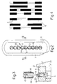
- the print head according to the present invention is particularly suitable for printing so-called CMC7 magnetic characters, an enlarged view of the character "2" of which is shown in Fig.4.
- These characters are printed using ink containing ferrite powder, and consist of thin vertical segments 3 of different lengths within the height of the character, and separated horizontally by gaps 4 of different widths.
- the overall appearance of the character printed as described above is such as to perfectly readable visually, while the combination of segments 3 and gaps 4 provides a code recognizable by a magnetic reader, and the data read by which may be transferred easily from a document, such as a cheque or similar, to a computer memory.
- Number 5 in Fig.1 indicates a hollow support housing a series of nine print pins 6, each having a body made of extremely hard, round-section wire, such as steel, tungsten, tungsten carbide or similar.
- Support 5 comprises a substantially conical front portion 7 having a seat 8 in which is fitted a first perforated plate 9 for guiding pins 6.
- a second guide plate 11 is fitted in a seat 12 on the front end of support 5.
- Plate 11 presents a series of nine holes 13 (Fig.s 2 and 3) arranged in a vertical row and the diameter of each of which is such as to accurately guide the portion of pin 6 adjacent to the printing surface 14 of the same.
- Holes 13 are generally arranged as close together as technologically possible.
- each pin 6 is engaged by a leaf spring 15 (Fig.1) for taking up any slack inside hole 13 and in a constant direction for all of pins 6.
- Printing surface 14 engages a standard print support through a magnetic ink ribbon (not shown).
- Support 5 also comprises a circular flange 16 secured to a cylindrical body 17 closed at the rear by a cover 18.
- Cylindrical body 17 houses a series of nine electromagnets 19 arranged circumferentially and energized selectively in known manner. Both body 17 and cover 18 are provided with flanges 20 for dissipating the heat produced by electromagnets 19.
- Each electromagnet 19 comprises a core 21 of magnetic material and a coil 22, and provides for activating a respective anchor 23 normally detached from the pole shoes of core 21 by a compression spring 24 housed in a seat 25.
- anchor 23 is guided by a frame 26 and is maintained by spring 24 with one end 29 resting on an inner retaining ring 27 acting as a damper. The other end of anchor 23 is maintained contacting an outer retaining ring 28 for positioning it against a fulcrum consisting of the outer edge of the pole shoe of core 21.
- each anchor 23 is secured to the rear end 31 of a respective pin 6 for controlling the printing of one dot.
- Pins 6 secured by ends 29 and guide plates 9 and 11 flex slightly and, at any rate, converge, so that, when pins 6 are activated, the distance between adjacent printing surfaces 14 is further reduced as compared with that of holes 13.
- Body 17 houses a printed circuit 32 connected to the control circuit of electromagnets 19 and having a series of laybys to which the electric terminals of coils 22 are connected in known manner.
- the printing surface 14 of each pin 6 is supported on a tapered end portion 33 of pin 6 (Fig.s 2 and 3) and is substantially rectangular with its longer side 34 parallel to the row of pins 6.
- the two faces of portion 33 relative to sides 34 of printing surface 14 are formed by flattening two parallel opposite surfaces on the end of the body of pin 6, so that the shorter sides 36 of the rectangle of surface 14 actually consist of two small arcs.
- Portion 33 is preferably 1 to 2 mm long, with a thickness ranging from 1/2 to 1/4 of the diameter of pin 6. With a pin diameter of 0.35 mm, the thickness of portion 33 may advantageously range from 0.12 to 0.13 mm.
- rear portion 31 of pin 6 is rigidly connected to end 29 of anchor 23 by means of a weld 37 (Fig.1) between the edge of end 29 and the two sides of portion 31.
- an anchor 23 activates a respective pin 6 to expel portion 33 from plate 11, and respective printing surface 14 engages the printing support through the magnetic ink ribbon, so as to print a thin vertical line.
- the various print lines combine to form a thin vertical segment with a highly defined, perfectly straight contour.
- a character generator to control the print head, it is therefore possible to print optical or magnetic font characters and, in particular, CMC7 magnetic font characters as shown in Fig.4.
- the print head according to the present invention can be manufactured using most of the components used for conventional heads featuring pins with circular printing surfaces. After welding portion 31 of each pin 6 to the edge of end 29 of respective anchor 23, at least some of the print head components are assembled inside support 5 and body 17.
- the print head is then fitted on to a grinder on which a fixture (not shown) rigidly secures pins 6 with portions 33 outside guide 11, as shown by the dotted line in Fig.3.
- the grinder is fitted with two parallel diamond wheels 38 and 39 separated by a spacer 41 of the same thickness as that required of portion 33. Sides 34 of portions 33 of pins 6 may thus all be machined in one grinding operation for enabling extremely low-cost manufacture of the print head.
- the advantages of the print head according to the present invention will be clear from the foregoing description, In particular, it provides for printing both character recognition, e.g. optical, fonts, and conventional fonts produced by one or more passes of the print head. Moreover, as compared with known types featuring a large number of pins, the print head according to the present invention provides for obtaining thinner segments with a more highly defined contour, and is much cheaper to produce.
- each pin may be welded to an actuating member separate from anchor 23; pins 6 may be spring-activated (stored energy), in which case, electromagnet 19 is energized for reloading the spring, and is de-energized for printing; tapered portion 33 may be designed differently, e.g.
- the print head may be designed for parallel printers, in which case, the smaller side 36 of the rectangle will be parallel to the horizontal row of pins; finally, the print head may be designed for printing straight horizontal and/or vertical segments by appropriately orienting the rectangle of the printing surface of each pin.
Landscapes
- Impact Printers (AREA)
- Printers Or Recording Devices Using Electromagnetic And Radiation Means (AREA)
Claims (9)
- Ein Druckerkopf mit einer Reihe von Stiften (6), die gleitend in die Druckstellung geführt sind, wobei die Stifte (6) wahlweise durch eine entsprechende Reihe von Elektromagneten (19) betätigt werden, wobei wenigstens der Abschnitt der Stifte (6) nahe der Druckstellung in einer vertikalen Zeile angeordnet ist, dadurch gekennzeichnet, daß jeder einzelne der Stifte (6) eine Druckoberfläche (14) im wesentlichen in der Form eines Rechteckes darbietet, wobei die Länge der kürzeren Kante (36) zwischen einem Viertel und der Hälfte der Länge der längeren Kante (34) beträgt, wobei die längere Seite (34) parallel zu der Spalte angeordnet ist, wodurch ein gleichzeitiger Betrieb einer Gruppe von nebeneinanderliegenden Stiften (6) das Drucken eines geradlinigen vertikalen Segmentes mit einer genau definierten Kontur bewirkt.
- Ein Druckerkopf nach Anspruch 1, dadurch gekennzeichnet, daß die Elektromagnete (19) am Umfang in einem zylindrischen Körper (17) angeordnet sind und wahlweise in einer solchen Weise betrieben werden, daß Zeichen mit wenigstens einem dünnen vertikalen Segment gedruckt werden und sowohl visuell als auch durch einen magnetischen oder optischen Zeichenleser lesbar sind.
- Ein Druckerkopf nach Anspruch 1 oder 2, dadurch gekennzeichnet, daß die Druckoberfläche (14) an einem sich verjüngenden Abschnitt (33) jedes Stiftes (6) angeordnet ist.
- Ein Druckerkopf nach Anspruch 4, dadurch gekennzeichnet, daß jeder Stift (6) einen kreisabschnittsförmigen Körper hat, der in einem entsprechenden Loch (13) in einem gemeinsamen Führungsteil (11) geführt ist, so daß die kürzere Kante (36) des Rechtecks die Form eines Bogens hat.
- Ein Druckerkopf nach Anspruch 4, dadurch gekennzeichnet, daß der kreisabschnittsförmige Körper einen Durchmesser von etwa 0,35 mm hat, wobei die kürzere Kante (36) im Bereich von 0,12 bis 0,13 mm ist, um den Druckerkopf in die Lage zu versetzen, senkrechte Segmente des CMC7-Zeichensatzes zu drucken.
- Ein Druckerkopf nach Anspruch 4 oder 5, dadurch gekennzeichnet, daß ein Abschnitt des Stiftes (6) an ein Betätigungsglied (23) eines entsprechenden Elektromagneten (19) angeschweißt ist, um so die längere Kante (34) parallel zu der Spalte zu halten.
- Ein Druckerkopf nach Anspruch 6, dadurch gekennzeichnet, daß das Betätigungsglied aus einem Anker des Elektromagneten (19) gebildet ist, wobei der Abschnitt (31) des Stiftes an die Kante eines Endes (29) des Ankers (23) angeschweißt ist.
- Ein Druckerkopf nach Anspruch 6 oder 7, dadurch gekennzeichnet, daß der sich verjüngende Abschnitt (33) durch Abflachen zweier paralleler Oberflächen (34) eines Endabschnittes des Stiftes (6) mittels zweier nebeneinander angeordneter Diamanträder gebildet ist, die in einem Abstand voneinander getrennt ist, der gleich der Größe der kürzeren Kante (36) ist.
- Ein Druckerkopf nach Anspruch 8, dadurch gekennzeichnet, daß die sich verjüngenden Abschnitte (33) der Stifte (6) so gestaltet sind, daß der Druckerkopf auf einen Schleifer aufgesetzt ist, der mit den Rädern (38, 39) verbunden ist, und daß die parallelen Oberflächen (34) aller Stifte (6) in einem einzigen Schleifvorgang bearbeitet werden.
Applications Claiming Priority (2)
| Application Number | Priority Date | Filing Date | Title |
|---|---|---|---|
| IT67296A IT1240202B (it) | 1990-04-20 | 1990-04-20 | Testina di stampa ad aghi |
| IT6729690 | 1990-04-20 |
Publications (2)
| Publication Number | Publication Date |
|---|---|
| EP0452934A1 EP0452934A1 (de) | 1991-10-23 |
| EP0452934B1 true EP0452934B1 (de) | 1995-07-19 |
Family
ID=11301239
Family Applications (1)
| Application Number | Title | Priority Date | Filing Date |
|---|---|---|---|
| EP91106236A Expired - Lifetime EP0452934B1 (de) | 1990-04-20 | 1991-04-18 | Matrixdruckkopf |
Country Status (3)
| Country | Link |
|---|---|
| EP (1) | EP0452934B1 (de) |
| DE (1) | DE69111288T2 (de) |
| IT (1) | IT1240202B (de) |
Families Citing this family (1)
| Publication number | Priority date | Publication date | Assignee | Title |
|---|---|---|---|---|
| DE4033698A1 (de) * | 1990-10-19 | 1992-04-30 | Mannesmann Ag | Verfahren zum drucken magnetisch lesbarer schriftzeichen und verwendung eines matrixdruckkopfes hierfuer sowie verfahren zu dessen herstellung |
Family Cites Families (1)
| Publication number | Priority date | Publication date | Assignee | Title |
|---|---|---|---|---|
| FR2183367A5 (de) * | 1972-05-04 | 1973-12-14 | Sagem |
-
1990
- 1990-04-20 IT IT67296A patent/IT1240202B/it active IP Right Grant
-
1991
- 1991-04-18 EP EP91106236A patent/EP0452934B1/de not_active Expired - Lifetime
- 1991-04-18 DE DE69111288T patent/DE69111288T2/de not_active Expired - Fee Related
Also Published As
| Publication number | Publication date |
|---|---|
| IT9067296A0 (it) | 1990-04-20 |
| EP0452934A1 (de) | 1991-10-23 |
| DE69111288T2 (de) | 1996-01-25 |
| DE69111288D1 (de) | 1995-08-24 |
| IT1240202B (it) | 1993-11-27 |
| IT9067296A1 (it) | 1991-10-20 |
Similar Documents
| Publication | Publication Date | Title |
|---|---|---|
| US4165940A (en) | Free flight head assembly for dot matrix printers and the like | |
| US3802543A (en) | Jewel bearings for printer heads and the like | |
| JPS624237B2 (de) | ||
| EP0134557B1 (de) | Montagevorrichtung für Punktmatrixdruckkopf | |
| US5975776A (en) | Dot matrix print head with unitary armature assembly and method of operation thereof | |
| KR900007522B1 (ko) | 단일 조각 전기자를 사용한 프린트 헤드 | |
| US3833105A (en) | Printer head assembly | |
| EP0452934B1 (de) | Matrixdruckkopf | |
| US3835975A (en) | Printer head assembly | |
| US4005770A (en) | Printer | |
| US3152540A (en) | Hammer mechanism | |
| US4503768A (en) | Single piece hammer module | |
| US4879947A (en) | Printhead which minimizes stray magnetic flux | |
| US5169246A (en) | Reduced diameter wire tips in a wire printing head | |
| US4695174A (en) | Magnetic circuit for matrix print head | |
| US4767226A (en) | Print head with wires which continuously contact the tip guide | |
| US3882986A (en) | Jewel bearings for printer heads and the like | |
| JPH0153191B2 (de) | ||
| US5039236A (en) | Print head with tapered conical return spring | |
| EP0372162B1 (de) | Punktmatrixdrucker mit Anschlagdruckkopf | |
| US5133613A (en) | Printing head using staggered arrangement needles | |
| JPH0432744B2 (de) | ||
| JPS59133069A (ja) | 印字ヘツド | |
| EP0267720A2 (de) | Flexible Drahtführung für Punktmatrixdrucker | |
| JPS58187374A (ja) | 印字ヘツド用ガイドプレ−ト |
Legal Events
| Date | Code | Title | Description |
|---|---|---|---|
| PUAI | Public reference made under article 153(3) epc to a published international application that has entered the european phase |
Free format text: ORIGINAL CODE: 0009012 |
|
| AK | Designated contracting states |
Kind code of ref document: A1 Designated state(s): DE ES FR GB SE |
|
| 17P | Request for examination filed |
Effective date: 19920414 |
|
| 17Q | First examination report despatched |
Effective date: 19931125 |
|
| GRAA | (expected) grant |
Free format text: ORIGINAL CODE: 0009210 |
|
| AK | Designated contracting states |
Kind code of ref document: B1 Designated state(s): DE ES FR GB SE |
|
| PG25 | Lapsed in a contracting state [announced via postgrant information from national office to epo] |
Ref country code: ES Free format text: THE PATENT HAS BEEN ANNULLED BY A DECISION OF A NATIONAL AUTHORITY Effective date: 19950719 |
|
| REF | Corresponds to: |
Ref document number: 69111288 Country of ref document: DE Date of ref document: 19950824 |
|
| ET | Fr: translation filed | ||
| PG25 | Lapsed in a contracting state [announced via postgrant information from national office to epo] |
Ref country code: SE Effective date: 19951019 |
|
| PGFP | Annual fee paid to national office [announced via postgrant information from national office to epo] |
Ref country code: GB Payment date: 19960409 Year of fee payment: 6 |
|
| PGFP | Annual fee paid to national office [announced via postgrant information from national office to epo] |
Ref country code: FR Payment date: 19960425 Year of fee payment: 6 |
|
| PLBE | No opposition filed within time limit |
Free format text: ORIGINAL CODE: 0009261 |
|
| 26N | No opposition filed | ||
| PG25 | Lapsed in a contracting state [announced via postgrant information from national office to epo] |
Ref country code: GB Effective date: 19970418 |
|
| GBPC | Gb: european patent ceased through non-payment of renewal fee |
Effective date: 19970418 |
|
| PG25 | Lapsed in a contracting state [announced via postgrant information from national office to epo] |
Ref country code: FR Free format text: LAPSE BECAUSE OF NON-PAYMENT OF DUE FEES Effective date: 19971231 |
|
| REG | Reference to a national code |
Ref country code: FR Ref legal event code: ST |
|
| PGFP | Annual fee paid to national office [announced via postgrant information from national office to epo] |
Ref country code: DE Payment date: 19980424 Year of fee payment: 8 |
|
| PG25 | Lapsed in a contracting state [announced via postgrant information from national office to epo] |
Ref country code: DE Free format text: LAPSE BECAUSE OF NON-PAYMENT OF DUE FEES Effective date: 20000201 |