EP0452949A1 - Appareil de commande pour émetteur I.R. - Google Patents
Appareil de commande pour émetteur I.R. Download PDFInfo
- Publication number
- EP0452949A1 EP0452949A1 EP91106321A EP91106321A EP0452949A1 EP 0452949 A1 EP0452949 A1 EP 0452949A1 EP 91106321 A EP91106321 A EP 91106321A EP 91106321 A EP91106321 A EP 91106321A EP 0452949 A1 EP0452949 A1 EP 0452949A1
- Authority
- EP
- European Patent Office
- Prior art keywords
- infrared
- housing
- sound
- control
- output connection
- Prior art date
- Legal status (The legal status is an assumption and is not a legal conclusion. Google has not performed a legal analysis and makes no representation as to the accuracy of the status listed.)
- Granted
Links
- 230000005540 biological transmission Effects 0.000 claims abstract description 12
- 230000005236 sound signal Effects 0.000 description 5
- 239000000969 carrier Substances 0.000 description 1
- 238000013519 translation Methods 0.000 description 1
- 230000014616 translation Effects 0.000 description 1
Images
Classifications
-
- H—ELECTRICITY
- H04—ELECTRIC COMMUNICATION TECHNIQUE
- H04B—TRANSMISSION
- H04B10/00—Transmission systems employing electromagnetic waves other than radio-waves, e.g. infrared, visible or ultraviolet light, or employing corpuscular radiation, e.g. quantum communication
- H04B10/50—Transmitters
Definitions
- the invention relates to a control transmitter for the multi-channel transmission of sound by means of infrared light, with a housing, with an output connection on the housing for connecting a connecting cable to at least one infrared power radiator, and with a control panel on one side of the housing, which has a plurality of setting elements for shows the influence of the sound transmitted in the individual sound channels.
- Such control transmitters are such.
- B. used in interpreter or tour systems to wirelessly transmit sound information in several languages using infrared light to the participants of a conference or the visitors of a museum.
- the control transmitter receives several sound signals and converts them into a modulated transmission signal at the output connection, with which one or more infrared power radiators are controlled, which are connected to the output connection via connecting cables.
- the infrared power emitters which for this purpose comprise an arrangement of many infrared emitting diodes, emit correspondingly modulated infrared light that can be received with small infrared receivers that are carried by conference participants or museum visitors.
- the infrared light is demodulated in the infrared receivers and the sound signals corresponding to the several sound channels are recovered, the user using a selector switch to determine which sound channel or which language he wants to listen to.
- the infrared power radiators are arranged in the room to be supplied with sound information in such a way that a uniform infrared light field predominates everywhere in the used part of the room.
- the control transmitter is operated and monitored by a technician. It is usually outside the publicly used part of the room in the shadow of infrared power emitters, e.g. B. in a corner of the room. As a result, the technician working on the control transmitter cannot or only poorly receive the emitted infrared light and thus has no complete control over the correct operation of the control transmitter on the control transmitter. It is indeed possible for him to control the sound signals supplied to the control transmitter. B. listening with headphones; however, he does not know whether the setting elements for influencing the sound transmitted in the individual sound channels are correctly set and whether the modulated transmission signal is formed correctly and completely.
- an infrared control transmitter of the type mentioned is provided on the outside of the housing in the area of the control panel Group of some infrared transmitter diodes are provided, which are electrically connected to the output terminal.
- the group of some infrared transmit diodes generates a small infrared light field in the immediate vicinity of the control transmitter, which conveys the same information as the main field generated by the infrared power radiators, since the group of some infrared transmit diodes has the same transmit signal are controlled from the output connection of the control transmitter like the infrared power radiators.
- the small field in the vicinity of the control transmitter can be received and monitored wirelessly by the operating technician with the aid of the usual infrared receiver, so that he is able to have complete control over the operation of the control transmitter. It can move freely and sometimes move away from the control transmitter without losing control because it then receives the main field generated by the infrared power radiators.
- the range of the infrared field generated on the control transmitter depends on the number of infrared transmit diodes provided on the control transmitter. Normally you will get by with a range of 1.5 to 2.0 m, which, depending on the performance of the individual infrared transmit diodes, requires a group of two to five infrared transmit diodes.
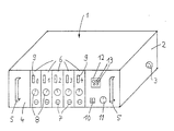
- the control transmitter shown in the figure is intended for the multi-channel transmission of sound using infrared light. It comprises a housing 1, in one side wall 2 of which there is an electrical output connection 3 for connecting a connecting cable (not shown) is provided, which leads to at least one infrared power radiator of conventional design.
- the front of the housing 1 is designed as a control panel 4.
- a carrying handle 5 is provided on the left and right for transport.
- inserts 6 each of which is assigned to a sound channel, namely the insert with the designation 0 the sound channel with the original sound and the inserts with the designation 1 to 4 the sound channels with translations of the original sound into different ones Languages.
- Each insert 6 has a plug connection 7 for the supply of a corresponding sound signal, a rotary knob 8 as a setting element for the sound level and a level meter 9.
- a power switch 10 for the entire control transmitter and a rotary knob 11 as a setting element for the level of the transmission signal pending at the output connection 3, which by modulating appropriate carriers with the sound signals supplied to the input connections 7 and Summary of the same is formed.
- a group 12 of five infrared transmission diodes 13 is attached in the control panel above the power switch 10 and the setting element 11.
- the infrared transmitter diodes 13 are conventional LEDs, as are also used in the infrared power emitters. They are arranged in such a way that the infrared light they produce radiates away from the control panel.
- the group 12 of infrared transmission diodes is electrically connected to the output connection 3 and contains the transmission signal from the control transmission device. Accordingly, the group 12 creates a small infrared light field in front of the control transmitter, which contains the sound information of the transmitted sound channels and can be received and listened to with a conventional, multi-channel infrared receiver.
Landscapes
- Physics & Mathematics (AREA)
- Electromagnetism (AREA)
- Engineering & Computer Science (AREA)
- Computer Networks & Wireless Communication (AREA)
- Signal Processing (AREA)
- Optical Communication System (AREA)
- Selective Calling Equipment (AREA)
Applications Claiming Priority (2)
| Application Number | Priority Date | Filing Date | Title |
|---|---|---|---|
| DE9004512U | 1990-04-20 | ||
| DE9004512U DE9004512U1 (de) | 1990-04-20 | 1990-04-20 | Infrarot-Steuersendegerät |
Publications (2)
| Publication Number | Publication Date |
|---|---|
| EP0452949A1 true EP0452949A1 (fr) | 1991-10-23 |
| EP0452949B1 EP0452949B1 (fr) | 1995-09-13 |
Family
ID=6853077
Family Applications (1)
| Application Number | Title | Priority Date | Filing Date |
|---|---|---|---|
| EP19910106321 Expired - Lifetime EP0452949B1 (fr) | 1990-04-20 | 1991-04-19 | Appareil de commande pour émetteur I.R. |
Country Status (4)
| Country | Link |
|---|---|
| EP (1) | EP0452949B1 (fr) |
| DE (2) | DE9004512U1 (fr) |
| DK (1) | DK0452949T3 (fr) |
| ES (1) | ES2078377T3 (fr) |
Citations (3)
| Publication number | Priority date | Publication date | Assignee | Title |
|---|---|---|---|---|
| GB2151870A (en) * | 1983-12-22 | 1985-07-24 | Anugraha Hotels Limited | Conference communications system |
| US4882776A (en) * | 1981-10-08 | 1989-11-21 | Canon Kabushiki Kaisha | Image information transmitting system |
| GB2218874A (en) * | 1988-05-20 | 1989-11-22 | Sony Corp | Optical atmospheric link system |
-
1990
- 1990-04-20 DE DE9004512U patent/DE9004512U1/de not_active Expired - Lifetime
-
1991
- 1991-04-19 DK DK91106321T patent/DK0452949T3/da active
- 1991-04-19 DE DE59106454T patent/DE59106454D1/de not_active Expired - Fee Related
- 1991-04-19 ES ES91106321T patent/ES2078377T3/es not_active Expired - Lifetime
- 1991-04-19 EP EP19910106321 patent/EP0452949B1/fr not_active Expired - Lifetime
Patent Citations (3)
| Publication number | Priority date | Publication date | Assignee | Title |
|---|---|---|---|---|
| US4882776A (en) * | 1981-10-08 | 1989-11-21 | Canon Kabushiki Kaisha | Image information transmitting system |
| GB2151870A (en) * | 1983-12-22 | 1985-07-24 | Anugraha Hotels Limited | Conference communications system |
| GB2218874A (en) * | 1988-05-20 | 1989-11-22 | Sony Corp | Optical atmospheric link system |
Also Published As
| Publication number | Publication date |
|---|---|
| EP0452949B1 (fr) | 1995-09-13 |
| DE59106454D1 (de) | 1995-10-19 |
| ES2078377T3 (es) | 1995-12-16 |
| DE9004512U1 (de) | 1990-06-21 |
| DK0452949T3 (da) | 1995-11-13 |
Similar Documents
| Publication | Publication Date | Title |
|---|---|---|
| DE19500694C2 (de) | HF-Bildwiedergabe-Vorrichtung | |
| DE3027917A1 (de) | Digitales verstaerkungssteuergeraet | |
| DE102006030878A1 (de) | Optisches Kommunikationssystem und Belichtungsvorrichtung und Anschlussbauelement, die für dasselbe verwendet werden | |
| DE4244356C2 (de) | Fernsehüberwachungssystem | |
| GB9904894D0 (en) | Optical networks | |
| DE19709174A1 (de) | Optisches Bussystem | |
| DE68928935T2 (de) | Optische Nebenschlussvorrichtung | |
| DE102016109667A1 (de) | Modulationseinrichtung und Beleuchtungseinrichtung | |
| EP0452949B1 (fr) | Appareil de commande pour émetteur I.R. | |
| DE102020111300A1 (de) | Fußmatte mit intelligenter Leuchtfunktion | |
| EP1013007B1 (fr) | Dispositif d'emission et de reception pour l'amplification entre des stations fixes et des stations mobiles avec detection du canal radio | |
| DE60131104T2 (de) | Verfahren und funkübertragungseinheit zur leistungsdetektion eines vielfachträgersignals | |
| DE102010054784A1 (de) | Leuchtensystem | |
| DE3543490C2 (fr) | ||
| DE69527902T2 (de) | System und vorrichtung zur vorautomatisierung der schaltanlagen eines gebäudes | |
| DE3852470T2 (de) | Optisches Übertragungsgerät. | |
| EP0185143A1 (fr) | Dispositif de commande à distance de plusieurs appareils audio et vidéo | |
| DE102020111160A1 (de) | Leuchtende Fahrzeugfußmatte | |
| DE10004290B4 (de) | Access-Knoten für optische Netze mit variablen Access-Wellenlängen, Nutzergerät zum Anschluss an einen solchen Access-Knoten, Verfahren zum Einspeisen von mehreren Signalen von mehreren Nutzern in ein optisches Netz und Verwendung eines Access-Knotens und mindestens eines Nutzergeräts zur Durchführung eines solchen Verfahrens | |
| DE1487625A1 (de) | Zweidraht-UEbertragungseinrichtung | |
| DE10349978B3 (de) | System, bestehend aus einem Haushaltsgerät und einem externen Gerät | |
| DE102004007057A1 (de) | Verfahren zur Übertragung eines DMX 512 Signals zur Steuerung von Beleuchtungskörpern | |
| DE2758864C3 (de) | Einrichtung zur wahlweisen Umschaltung von zwei Signalwegen, insbesondere zur Umschaltung eines Stereogerätes auf zwei Plattenspieler | |
| DE69417158T2 (de) | Manuelles Steuergerät in Modulbauweise für einem Kram | |
| DE3732740C2 (fr) |
Legal Events
| Date | Code | Title | Description |
|---|---|---|---|
| PUAI | Public reference made under article 153(3) epc to a published international application that has entered the european phase |
Free format text: ORIGINAL CODE: 0009012 |
|
| AK | Designated contracting states |
Kind code of ref document: A1 Designated state(s): DE DK ES FR GB IT NL |
|
| 17P | Request for examination filed |
Effective date: 19920123 |
|
| 17Q | First examination report despatched |
Effective date: 19940531 |
|
| GRAA | (expected) grant |
Free format text: ORIGINAL CODE: 0009210 |
|
| AK | Designated contracting states |
Kind code of ref document: B1 Designated state(s): DE DK ES FR GB IT NL |
|
| GBT | Gb: translation of ep patent filed (gb section 77(6)(a)/1977) |
Effective date: 19950919 |
|
| REF | Corresponds to: |
Ref document number: 59106454 Country of ref document: DE Date of ref document: 19951019 |
|
| ET | Fr: translation filed | ||
| REG | Reference to a national code |
Ref country code: DK Ref legal event code: T3 |
|
| ITF | It: translation for a ep patent filed | ||
| REG | Reference to a national code |
Ref country code: ES Ref legal event code: FG2A Ref document number: 2078377 Country of ref document: ES Kind code of ref document: T3 |
|
| PLBE | No opposition filed within time limit |
Free format text: ORIGINAL CODE: 0009261 |
|
| STAA | Information on the status of an ep patent application or granted ep patent |
Free format text: STATUS: NO OPPOSITION FILED WITHIN TIME LIMIT |
|
| 26N | No opposition filed | ||
| REG | Reference to a national code |
Ref country code: GB Ref legal event code: IF02 |
|
| NLS | Nl: assignments of ep-patents |
Owner name: BRAEHLER ICS KONFERENZTECHNIK INTERNATIONAL CONGRE |
|
| REG | Reference to a national code |
Ref country code: ES Ref legal event code: PC2A |
|
| REG | Reference to a national code |
Ref country code: FR Ref legal event code: TP |
|
| REG | Reference to a national code |
Ref country code: FR Ref legal event code: CA |
|
| REG | Reference to a national code |
Ref country code: FR Ref legal event code: RM |
|
| REG | Reference to a national code |
Ref country code: GB Ref legal event code: 732E |
|
| PGFP | Annual fee paid to national office [announced via postgrant information from national office to epo] |
Ref country code: ES Payment date: 20090424 Year of fee payment: 19 Ref country code: DK Payment date: 20090423 Year of fee payment: 19 |
|
| PGFP | Annual fee paid to national office [announced via postgrant information from national office to epo] |
Ref country code: NL Payment date: 20090427 Year of fee payment: 19 Ref country code: IT Payment date: 20090427 Year of fee payment: 19 Ref country code: FR Payment date: 20090420 Year of fee payment: 19 Ref country code: DE Payment date: 20090430 Year of fee payment: 19 |
|
| PGFP | Annual fee paid to national office [announced via postgrant information from national office to epo] |
Ref country code: GB Payment date: 20090424 Year of fee payment: 19 |
|
| REG | Reference to a national code |
Ref country code: NL Ref legal event code: V1 Effective date: 20101101 |
|
| REG | Reference to a national code |
Ref country code: DK Ref legal event code: EBP |
|
| GBPC | Gb: european patent ceased through non-payment of renewal fee |
Effective date: 20100419 |
|
| REG | Reference to a national code |
Ref country code: FR Ref legal event code: ST Effective date: 20101230 |
|
| PG25 | Lapsed in a contracting state [announced via postgrant information from national office to epo] |
Ref country code: NL Free format text: LAPSE BECAUSE OF NON-PAYMENT OF DUE FEES Effective date: 20101101 |
|
| PG25 | Lapsed in a contracting state [announced via postgrant information from national office to epo] |
Ref country code: DE Free format text: LAPSE BECAUSE OF NON-PAYMENT OF DUE FEES Effective date: 20101103 |
|
| PG25 | Lapsed in a contracting state [announced via postgrant information from national office to epo] |
Ref country code: IT Free format text: LAPSE BECAUSE OF NON-PAYMENT OF DUE FEES Effective date: 20100419 Ref country code: GB Free format text: LAPSE BECAUSE OF NON-PAYMENT OF DUE FEES Effective date: 20100419 |
|
| PG25 | Lapsed in a contracting state [announced via postgrant information from national office to epo] |
Ref country code: DK Free format text: LAPSE BECAUSE OF NON-PAYMENT OF DUE FEES Effective date: 20100503 |
|
| REG | Reference to a national code |
Ref country code: ES Ref legal event code: FD2A Effective date: 20110707 |
|
| PG25 | Lapsed in a contracting state [announced via postgrant information from national office to epo] |
Ref country code: ES Free format text: LAPSE BECAUSE OF NON-PAYMENT OF DUE FEES Effective date: 20110627 |
|
| PG25 | Lapsed in a contracting state [announced via postgrant information from national office to epo] |
Ref country code: ES Free format text: LAPSE BECAUSE OF NON-PAYMENT OF DUE FEES Effective date: 20100420 |
|
| PG25 | Lapsed in a contracting state [announced via postgrant information from national office to epo] |
Ref country code: FR Free format text: LAPSE BECAUSE OF NON-PAYMENT OF DUE FEES Effective date: 20100430 |