EP0452985A2 - System zur Bilderzeugung mittels LIDAR und Gerät zur Bestimmung des K-Faktors unter Verwendung von abstimmbaren und Festfrequenz-Laser-Sendern - Google Patents
System zur Bilderzeugung mittels LIDAR und Gerät zur Bestimmung des K-Faktors unter Verwendung von abstimmbaren und Festfrequenz-Laser-Sendern Download PDFInfo
- Publication number
- EP0452985A2 EP0452985A2 EP91110375A EP91110375A EP0452985A2 EP 0452985 A2 EP0452985 A2 EP 0452985A2 EP 91110375 A EP91110375 A EP 91110375A EP 91110375 A EP91110375 A EP 91110375A EP 0452985 A2 EP0452985 A2 EP 0452985A2
- Authority
- EP
- European Patent Office
- Prior art keywords
- light
- water
- laser
- pulses
- wavelength
- Prior art date
- Legal status (The legal status is an assumption and is not a legal conclusion. Google has not performed a legal analysis and makes no representation as to the accuracy of the status listed.)
- Withdrawn
Links
Images


Classifications
-
- H—ELECTRICITY
- H04—ELECTRIC COMMUNICATION TECHNIQUE
- H04B—TRANSMISSION
- H04B13/00—Transmission systems characterised by the medium used for transmission, not provided for in groups H04B3/00 - H04B11/00
- H04B13/02—Transmission systems in which the medium consists of the earth or a large mass of water thereon, e.g. earth telegraphy
-
- G—PHYSICS
- G01—MEASURING; TESTING
- G01S—RADIO DIRECTION-FINDING; RADIO NAVIGATION; DETERMINING DISTANCE OR VELOCITY BY USE OF RADIO WAVES; LOCATING OR PRESENCE-DETECTING BY USE OF THE REFLECTION OR RERADIATION OF RADIO WAVES; ANALOGOUS ARRANGEMENTS USING OTHER WAVES
- G01S17/00—Systems using the reflection or reradiation of electromagnetic waves other than radio waves, e.g. lidar systems
- G01S17/88—Lidar systems specially adapted for specific applications
- G01S17/89—Lidar systems specially adapted for specific applications for mapping or imaging
-
- G—PHYSICS
- G01—MEASURING; TESTING
- G01S—RADIO DIRECTION-FINDING; RADIO NAVIGATION; DETERMINING DISTANCE OR VELOCITY BY USE OF RADIO WAVES; LOCATING OR PRESENCE-DETECTING BY USE OF THE REFLECTION OR RERADIATION OF RADIO WAVES; ANALOGOUS ARRANGEMENTS USING OTHER WAVES
- G01S7/00—Details of systems according to groups G01S13/00, G01S15/00, G01S17/00
- G01S7/48—Details of systems according to groups G01S13/00, G01S15/00, G01S17/00 of systems according to group G01S17/00
- G01S7/483—Details of pulse systems
- G01S7/484—Transmitters
Definitions
- Patent 4,964,721 relates to an imaging lidar system which controls camera gating based on input from the aircraft onboard altimeter and uses a computer to thereby adjust total time delay so as to automatically track changing platform altitude.
- Patent 4,967,270 relates to a lidar system employing a plurality of gated cameras which are individually triggered after preselected time delays to obtain multiple subimages laterally across a target image. These multiple subimages are then put together in a mosaic in a computer to provide a complete image of a target plane preferably using only a single light pulse.
- USSN 565,631 filed August 10, 1990 which is also assigned to the assignee hereof and fully incorporated herein by reference, relates to an airborne imaging lidar system which employs multiple pulsed laser transmitters, multiple gated and intensified array camera receivers, an optical scanner for increased field of regard, and a computer for system control, automatic target detection and display generation.
- USSN 565,631 provides a means for rapidly searching a large volume of the backscattering medium (e.g., water) for specified targets and improves upon prior art devices in performance as a result of having more energy in each laser pulse (due to simultaneous operation of multiple lasers) and a more sensitive detection system using multiple cameras.
- the backscattering medium e.g., water
- the above-described imaging lidar systems utilize lasers which do not operate at the optimum wavelength for light propagation in the ocean and cannot reach the acceptance frequencies required by certain optical receivers.
- the resolution of objects below certain depths in the ocean is not satisfactory. This problem is particularly troublesome as there is a perceived need to detect submerged objects at ocean depths of up to several hundred feet.
- the present invention provides a tunable and/or fixed frequency laser light source for use in both underwater lidar and underwater communications applications.
- Tunability (or the ability to alter and fix the wavelength to a set frequency) is important for imaging lidar and underwater communications applications, since it is desirable to have an illuminating light source which operates at a light wavelength which has the best transmission characteristics for the type of water in which operation is desired.
- the transmitting or illuminating laser must not only be tuned or set to the optimum wavelength for transmission, it must also be tuned or set to the middle of the acceptance bandwidth of the filter receiver (such as the atomic resonance filter-receiver described in U.S. Patent No. 4,292,526).
- the filter receiver is selected for operation at or near the wavelength for optical transmission through the water, so that it is the acceptance frequency of the filter which determines the laser transmitter wavelength for this (communications) application.
- Other less clear waters will attenuate light pulses more strongly, with maximum transmission occurring at progressively longer wavelengths, and with less frequency dependence.
- Most investigators agree on the general shape of these curves.
- Class 1 For the most transparent of waters (Class 1) the presence of certain suspended organic material called "gelbstoff” causes a loss in transmissivity at wavelengths shorter than the Jerlov minimum. This material is normally found in clear water closer to land masses or in enclosed bodies of water. This situation is shown by the two curves for classes 1, 1 a and 1 b water shown in FIGURE 1A.
- a region 10 exists where optimum transmission is obtained.
- a transmitter operating in this region will be able to penetrate the ocean at least 50 meters before it is attenuated l/e of its initial intensity as it enters the ocean.
- a laser transmitter operating in the deep ocean be tuned to or set to operate at frequencies in that optical region.
- the water is normally of a much poorer quality, Class 111 or worse.
- the frequency dependence is much less pronounced, with a broad minimum at the longer wavelengths, in region 12. Since pulsed lasers operating at this wavelength are generally far more efficient and more technologically mature, they are to be desired for the shallow water application.
- even in deep ocean areas where the water above the thermocline may have worse transmission properties than Class 1, below the thermocline all deep ocean water is Class 1, at least down to the deep scattering layer (about 1100 feet).
- FIGURE 1B the regions in the world and their water classes are shown. Most of the open ocean is Class 1A and 1B water, with regions such as the Sargasso Sea 14 and the Eastern Mediterranean 16 representing very clear open ocean water, and the region off the Amazon Delta 18 and the Galapagos Islands off Ecuador 20 representing ocean water with much poorer transmission characteristics.
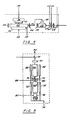
- the laser transmitter component 22 of the system in FIGURE 2 may be considered modular to the overall system, barring slightly altered power requirements and output wavelength which requires Lyot filters 26 consistent with the particular wavelength used.
- the schematic of FIGURE 2 taken together with prior Patent Nos. 4,862,257 and 4,964,721 readily provide a description of this imaging lidar system to one of ordinary skill in the art. However, it is instructive to describe the interfaces of the laser with the system.
- the precision timing generator 28 triggers the Marx bank discharge across the flashlamps 30 which pump the dye laser.
- an appropriate dye would be, for example, Coumarin 480 or Coumarin 460.
- the 480 and 460 represent the light wavelengths in nanometers at which each laser dye transmits.
- the lidar system can be operated at night or during the daytime. During daylight hours a Lyot (birefringement) or atomic resonance filter 26 must be used. These filters are lossy, depending on their acceptance angle and acceptance bandwidths.
- the operation of the lidar system of FIGURE 3 is the same as shown in FIGURE 2 with the exception that much less power is required to pump the laser system, and since the transmitter output wavelength does not vary, a Lyot filter 34 centered at a wavelength of 532 nm is used at the imaging camera input optics to exclude sunlight during daytime operations.
- an excimer laser is shown as a pumping source for a tunable dye laser.
- the excimer laser is a discharge pumped X-ray preionized XeCl laser, operating at 308 nm. This is well within the pump band of dye lasers operating in the blue green wavelength regions using Coumarin 480, for example.
- Power is supplied to the pulse forming network (PNF) 36 from the laser power supply output 38.
- the PFN can be of the solid state type or a self healing liquid PFN.
- the pulses are then switched out by the switch 40 to electrodes inside the excimer laser cavity 42, bounded by mirrors 44 where they discharge into and excite the excimer gas mixture, producing the lasing medium.
- the lasing gas mixture is preconditioned by the x-ray preionizer 46, and its external power source 48. Parasitic power 50 is also required for the gas and cooling water circulating systems, integral with the cavity.
- the uv light pulse 52 (typically 308 nm, for the XeCl laser, although wavelengths of 193 nm, 248 nm and 351 nm are also available form ArF, KrF and XeF respectively) is then expanded by the coupling optics 54 thus irradiating the dye solution 56 in the dye laser cavity bounded by mirrors 58.
- the Q-switch 60 and the electro-optic tuner 62 with their respective controls and inputs 64 and 66. Blue light then proceeds across the boundary of the transmitter module to the output optics as shown in FIGURES 2 and 3. A small amount of light is diverted by beam splitter 67 back to the power monitor for continuous recording of the laser output.
- a flashlamp pumped solid state laser system operating on a vibronic transition e.g., TiSapphire, Alexandrite and Cr:LiSAF
- the system of FIGURE 5 is a "master oscillator power amplifier” or “MOPA” configuration. Master oscillator is commonly referred to as “MO” and power amplifiers as “PA”. A master oscillator with two power amplifiers following in series would be called a "MOPAPA" configuration. Any of the preferred embodiments described herein could be any combination of power amplifiers with a given master oscillator.
- these signals are tuned to enter an atomic resonance filter receiver by use of the feedback loop 116 which incorporates an atomic resonance filter using the same metal as the receiver; for instance, cesium metal, which operates at wavelengths around 455 and 459 nm.
- the use of these transmitters is a significant improvement over the prior art of, for example, U.S. Patent No. 4,963,024 which describes a device primarily suited for measurements at a wavelength of 532 nm.
- the lasing gas mixture is preconditioned by the X-ray preionizer 132, and its external power source 134. For this application, however, a portion of the uv light initially generated by the excimer is drawn off to pump a small dye laser 136, bounded by mirrors 138 and a tuner 140 tuned to the output wavelength of interest, but within the emission band of the C to A transition. As noted previously, this tuner 140 can be controlled by a small atomic resonance filter. This arrangement is known in the art as self injection. Other schemes are also available, such as discharge pumping a small KrF excimer laser which, in turn, pumps the dye laser.
- a titanium sapphire laser amplifier is shown with the pumping energy provided by a diode pumped frequency doubled YAG laser.
- This particular embodiment completely eliminates the use of flashlamps.
- the configuration shown is a combination of a single Nd:YAG "MOPA" system pumping a tunable Ti:Sapphire laser in an optical cavity.
- the power supply 201 and power connection 203 provide energy to the pulse forming network 202, triggered by a signal 224 from the pulse timing generator 199.
- the pulses, generated at the desired transmitter pulse repetition rate, are delivered through the transmission line 204 to two separate diode arrays; the diode arrays 205 consisting of Gallium Aluminum Arsenide diodes (GaAlAs) prepared so that they radiate at a wavelength of 808 nm, and larger diode arrays 212 operating at the same wavelength and pumping the Nd:YAG amplifier rod 211. This wavelength is within an absorption band of Nd:YAG centered at 808 nm.
- GaAlAs Gallium Aluminum Arsenide diodes
- the doubled pulse 215 is then passed through two tuning prisms or mirrors 216 and reflected off of a turning mirror 217 and into the Ti:Sapphire cavity off one of the two cavity mirrors 218. This situation is shown in detail in FIGURE 7B.
- the doubled pulse enters the Ti:Sapphire rod 221 from the turning mirror 217 and the cavity mirror 218 at an off axis angle which is very small.
- a Brewster prism (not shown) can also be used for introducing the pumping light.
- the pulse generated from this pumping may be Q-switched out as was done in the Nd:YAG cavity with Q-switch 208, or it may be allowed to discharge spontaneously from the resonant cavity at the wavelength determined by the electro optic tuning element 214.
- the tuning element 214 may utilize a feedback loop with various embodiments using wave meters and other optical elements as standards in the feedback loop 300 connected electrically to the tuning element through 220.
- Input to the feedback loop is provided by a sampling mirror 301 which directs a very small part 303 of the pulse 222 diverted into the feedback loop by the turning mirror(s) 302.
- the light pulse 223 Upon exiting the cavity, the light pulse 223 is doubled in frequency doubling crystal 225. This produces light pulses 226 whose wavelengths can range from 380 to 500 nm. It can be seen that this makes possible delivery of nanosecond, high energy pulses at high repetition rates (greater than 100 Hz), high wallplug efficiencies (approximately 3%) and light pulses available at the wavelengths most appropriate for submarine communications and lidar imaging. Since flashlamps are not required, the lifetime of this transmitter can be tens of thousands of hours.
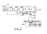
- FIGURE 8 presents the platform configuration for using the various transmitters described herein for communications purposes (as opposed to the lidar system of FIGURES 2 and 3).
- a transmission 150 is received by an rf antenna 152 on a airborne platform 154 and sent along transmission lines 156 of the rf (radio frequency) amplifier, receiver and demodulator 158.
- the message is processed and put in digital form and sent to the digital pulse coder 162.
- Digital pulses are then sent to the transmitter module 164 for transmission.
- the technique for sending messages by pulses transmitted at varying intervals is called "pulse spacing modulation" (See Helstrom, C, IEEE Trans. Inf. Theory, IT-15,31 (1970); Bar-David, I.J.
- the transmissions are transmitted downward by the expanding optics 166 to a filter receiver 168 on an undersea platform 170.
- the signal is registered on a photo detector 172 decoded at 174 and processed at 176.
- the lasers described in FIGURES 2, 4, 5, 6, 7 and 7A are all appropriate for laser undersea communications, and can be used modularly in 164 depending on space, power availability etc.
- the light from transmitter 164 is directed downward through the expanding optics 166 to an atomic resonance filter (QLORD) 168 with cesium vapor.
- QLORD atomic resonance filter
- the acceptance wavelengths for this filter are 459 nm and 455 nm in the middle of the optimum transmission band 12, shown in FIGURE 1B.
- the signals are then detected in the photodetector 172.
- the pulses enter the pulse decoder 174, where they are decoded and the decoded message is stored out or printed on the mission equipment 176.
- Cesium vapor operates on atomic transitions. Therefore it can be used as an absolute standard.
- the laser transmitter 164 is controlled by a feedback loop 180, with a cesium detector 167 viewing a sample of the main output beam 310 sampled by a mirror 169.
- the use of the QLORD as both electro optic control element and receiver insures that the transmitter will remain in the acceptance bandwidth of the receiver.
- filter-detectors 167, 168 comprise known atomic resonance or Q-Lord filter-detectors as described in U.S. Patent 4,292,526 which is incorporated herein by reference.
- a preferred filter-detector utilizing an inert buffer gas is described in U.S. Application Serial No. 446,644 filed December 6, 1989, assigned to the assignee hereof and fully incorporated herein by reference.
- the several lasers depicted in FIGURES 2-7 are preferably operated in a manner which extracts the maximum energy from the laser in the form of short pulses repeatedly generated in a single pumping cycle.
- Such a technique is described in detail in U.S. Patent Application Serial No. filed contemporaneously with this application by R. Norris Keeler and entitled "Imaging Lidar System Employing Multipulse Single and Multiple Gating for Single and Stacked Frames" (Attorney Docket No. 90-1388).
Landscapes
- Engineering & Computer Science (AREA)
- Physics & Mathematics (AREA)
- Computer Networks & Wireless Communication (AREA)
- General Physics & Mathematics (AREA)
- Radar, Positioning & Navigation (AREA)
- Remote Sensing (AREA)
- Electromagnetism (AREA)
- Signal Processing (AREA)
- Optical Radar Systems And Details Thereof (AREA)
Applications Claiming Priority (4)
| Application Number | Priority Date | Filing Date | Title |
|---|---|---|---|
| US07/632,398 US5181135A (en) | 1990-12-21 | 1990-12-21 | Optical underwater communications systems employing tunable and fixed frequency laser transmitters |
| US07/632,377 US5091778A (en) | 1990-12-21 | 1990-12-21 | Imaging lidar systems and K-meters employing tunable and fixed frequency laser transmitters |
| US632377 | 1990-12-21 | ||
| US632398 | 1990-12-21 |
Publications (2)
| Publication Number | Publication Date |
|---|---|
| EP0452985A2 true EP0452985A2 (de) | 1991-10-23 |
| EP0452985A3 EP0452985A3 (en) | 1993-05-19 |
Family
ID=27091616
Family Applications (1)
| Application Number | Title | Priority Date | Filing Date |
|---|---|---|---|
| EP19910110375 Withdrawn EP0452985A3 (en) | 1990-12-21 | 1991-06-24 | Imaging lidar systems and k-meters employing tunable and fixed frequency laser transmitters |
Country Status (1)
| Country | Link |
|---|---|
| EP (1) | EP0452985A3 (de) |
Cited By (6)
| Publication number | Priority date | Publication date | Assignee | Title |
|---|---|---|---|---|
| GB2256766A (en) * | 1991-09-17 | 1992-12-16 | Kaman Aerospace Corp | Reducing optical noise |
| EP0474264A3 (en) * | 1991-04-24 | 1993-06-16 | Kaman Aerospace Corporation | Spectrally dispersive imaging lidar method and apparatus |
| CN102608037A (zh) * | 2012-04-11 | 2012-07-25 | 哈尔滨工业大学(威海) | 一种快速测量光衰减系数的测量装置及测量方法 |
| CN110954921A (zh) * | 2019-12-03 | 2020-04-03 | 浙江大学 | 一种基于块匹配3d协同滤波的激光雷达回波信号信噪比提升方法 |
| CN111766568A (zh) * | 2020-07-09 | 2020-10-13 | Oppo广东移动通信有限公司 | 飞行时间测距系统的抗干扰方法、装置及终端设备 |
| DE102019212608A1 (de) * | 2019-08-22 | 2021-02-25 | Robert Bosch Gmbh | LIDAR-System als Umgebungssensor mit zwei aufeinander folgenden Laserimpulsen |
Family Cites Families (5)
| Publication number | Priority date | Publication date | Assignee | Title |
|---|---|---|---|---|
| US3788742A (en) * | 1971-06-24 | 1974-01-29 | Westinghouse Electric Corp | Gas monitoring system |
| GB2158668B (en) * | 1984-05-08 | 1987-10-14 | British Aerospace | Communications systems |
| US4707128A (en) * | 1984-12-31 | 1987-11-17 | Subsea Engineering Associates, Inc. | Turbid media viewing system |
| US4829597A (en) * | 1986-09-29 | 1989-05-09 | The Aerospace Corporation | Low solar background, high sensitivity active atomic resonance filter for underwater laser communications |
| US4963024A (en) * | 1988-07-07 | 1990-10-16 | Kaman Aerospace Corporation | Method and apparatus for determining K factor |
-
1991
- 1991-06-24 EP EP19910110375 patent/EP0452985A3/en not_active Withdrawn
Cited By (8)
| Publication number | Priority date | Publication date | Assignee | Title |
|---|---|---|---|---|
| EP0474264A3 (en) * | 1991-04-24 | 1993-06-16 | Kaman Aerospace Corporation | Spectrally dispersive imaging lidar method and apparatus |
| GB2256766A (en) * | 1991-09-17 | 1992-12-16 | Kaman Aerospace Corp | Reducing optical noise |
| GB2256766B (en) * | 1991-09-17 | 1995-08-30 | Kaman Aerospace Corp | Apparatus and method for reducing noise in imaging lidar,underwater communications and lidar bathymetry systems |
| CN102608037A (zh) * | 2012-04-11 | 2012-07-25 | 哈尔滨工业大学(威海) | 一种快速测量光衰减系数的测量装置及测量方法 |
| DE102019212608A1 (de) * | 2019-08-22 | 2021-02-25 | Robert Bosch Gmbh | LIDAR-System als Umgebungssensor mit zwei aufeinander folgenden Laserimpulsen |
| CN110954921A (zh) * | 2019-12-03 | 2020-04-03 | 浙江大学 | 一种基于块匹配3d协同滤波的激光雷达回波信号信噪比提升方法 |
| CN111766568A (zh) * | 2020-07-09 | 2020-10-13 | Oppo广东移动通信有限公司 | 飞行时间测距系统的抗干扰方法、装置及终端设备 |
| CN111766568B (zh) * | 2020-07-09 | 2023-06-30 | Oppo广东移动通信有限公司 | 飞行时间测距系统的抗干扰方法、装置及终端设备 |
Also Published As
| Publication number | Publication date |
|---|---|
| EP0452985A3 (en) | 1993-05-19 |
Similar Documents
| Publication | Publication Date | Title |
|---|---|---|
| US5091778A (en) | Imaging lidar systems and K-meters employing tunable and fixed frequency laser transmitters | |
| US5181135A (en) | Optical underwater communications systems employing tunable and fixed frequency laser transmitters | |
| US5164823A (en) | Imaging lidar system employing multipulse single and multiple gating for single and stacked frames | |
| US5192978A (en) | Apparatus and method for reducing solar noise in imaging lidar, underwater communications and lidar bathymetry systems | |
| Petrie et al. | Introduction to laser ranging, profiling, and scanning | |
| US4902127A (en) | Eye-safe coherent laser radar | |
| CN100356640C (zh) | 产生太赫兹辐射的装置以及半导体元件 | |
| RU2333473C2 (ru) | Мобильное устройство и способ для дистанционного обнаружения скоплений газообразного метана | |
| JPS6026962B2 (ja) | レ−ザ−シ−ロメ−タ− | |
| CA1068386A (en) | Method and apparatus for tuning high power lasers | |
| NZ229854A (en) | Determining transmissivity and depth of water using pulsed laser | |
| US4447149A (en) | Pulsed laser radar apparatus | |
| Asaka et al. | 1.5-um eye-safe coherent lidar system for wind velocity measurement | |
| US20200200876A1 (en) | Two micrometer laser transmitter for 3-d doppler wind lidar for space applications | |
| EP0452985A2 (de) | System zur Bilderzeugung mittels LIDAR und Gerät zur Bestimmung des K-Faktors unter Verwendung von abstimmbaren und Festfrequenz-Laser-Sendern | |
| US4355893A (en) | Eye-safe laser cloud height rangefinder | |
| US5917843A (en) | Laser cavity assembly | |
| US4868833A (en) | Raman cavity dump laser | |
| US4054852A (en) | Solid state blue-green laser with high efficiency laser pump | |
| US3972007A (en) | Laser | |
| US5420878A (en) | Production of laser light with controllable atmospheric absorption | |
| Ferguson | Blue-green lasers for underwater applications | |
| Minden et al. | A range-resolved Doppler imaging sensor based on fiber lasers | |
| GB2266406A (en) | High power laser source | |
| Stultz et al. | Eyesafe high-pulse-rate laser progress at Hughes |
Legal Events
| Date | Code | Title | Description |
|---|---|---|---|
| PUAI | Public reference made under article 153(3) epc to a published international application that has entered the european phase |
Free format text: ORIGINAL CODE: 0009012 |
|
| AK | Designated contracting states |
Kind code of ref document: A2 Designated state(s): AT BE CH DE DK ES FR GB GR IT LI LU NL SE |
|
| PUAL | Search report despatched |
Free format text: ORIGINAL CODE: 0009013 |
|
| AK | Designated contracting states |
Kind code of ref document: A3 Designated state(s): AT BE CH DE DK ES FR GB GR IT LI LU NL SE |
|
| 17P | Request for examination filed |
Effective date: 19930825 |
|
| 17Q | First examination report despatched |
Effective date: 19950828 |
|
| STAA | Information on the status of an ep patent application or granted ep patent |
Free format text: STATUS: THE APPLICATION IS DEEMED TO BE WITHDRAWN |
|
| 18D | Application deemed to be withdrawn |
Effective date: 19960308 |