EP0453030B1 - Anordnung zur Regelung von einem Leuchtstoffrohr - Google Patents
Anordnung zur Regelung von einem Leuchtstoffrohr Download PDFInfo
- Publication number
- EP0453030B1 EP0453030B1 EP91200862A EP91200862A EP0453030B1 EP 0453030 B1 EP0453030 B1 EP 0453030B1 EP 91200862 A EP91200862 A EP 91200862A EP 91200862 A EP91200862 A EP 91200862A EP 0453030 B1 EP0453030 B1 EP 0453030B1
- Authority
- EP
- European Patent Office
- Prior art keywords
- light
- fluorescent lamp
- stage amplifier
- sensing circuit
- terminals
- Prior art date
- Legal status (The legal status is an assumption and is not a legal conclusion. Google has not performed a legal analysis and makes no representation as to the accuracy of the status listed.)
- Expired - Lifetime
Links
- 238000004020 luminiscence type Methods 0.000 description 5
- 239000004973 liquid crystal related substance Substances 0.000 description 4
- 239000003990 capacitor Substances 0.000 description 3
- 230000007423 decrease Effects 0.000 description 2
- 238000000034 method Methods 0.000 description 2
- 238000010586 diagram Methods 0.000 description 1
- 230000004048 modification Effects 0.000 description 1
- 238000012986 modification Methods 0.000 description 1
Images
Classifications
-
- H—ELECTRICITY
- H05—ELECTRIC TECHNIQUES NOT OTHERWISE PROVIDED FOR
- H05B—ELECTRIC HEATING; ELECTRIC LIGHT SOURCES NOT OTHERWISE PROVIDED FOR; CIRCUIT ARRANGEMENTS FOR ELECTRIC LIGHT SOURCES, IN GENERAL
- H05B41/00—Circuit arrangements or apparatus for igniting or operating discharge lamps
- H05B41/14—Circuit arrangements
- H05B41/36—Controlling
- H05B41/38—Controlling the intensity of light
- H05B41/39—Controlling the intensity of light continuously
- H05B41/392—Controlling the intensity of light continuously using semiconductor devices, e.g. thyristor
- H05B41/3921—Controlling the intensity of light continuously using semiconductor devices, e.g. thyristor with possibility of light intensity variations
- H05B41/3922—Controlling the intensity of light continuously using semiconductor devices, e.g. thyristor with possibility of light intensity variations and measurement of the incident light
Definitions
- the invention also involves a sensing circuit for generating a signal representative of ambient light intensity, suitable for use in such a fluorescent lamp controller.
- One of the objects of this invention is the conservation of energy.
- backlighting is used to provide contrast between the ambient light incident upon the display and the display itself.
- This invention controls the amount of light from fluorescent lamps used as such backlighting in accordance with the amount of ambient light incident on the display. It conserves energy by reducing the luminescence of a backlighting fluorescent lamp as the incident ambient light decreases.
- a sensing circuit is connected to a ballast means for the fluorescent lamp which ballast means include a light control circuit for controlling the luminescence of the fluorescent lamp.
- the sensing circuit includes a light sensor, a first and a second stage amplifier and two terminals and produces a signal representative of the light impinging upon the light sensor.
- the sensing circuit is operable from power derived from the ballast means via the terminals and controls the light control circuit so that the luminescence emanating from the fluorescent lamp is increased in accordance with increases in the light striking the light sensor.
- European Patent Application EP-A-0416697 which was only published after the priority date of the present application, discloses a light sensing circuit for controlling the light output of fluorescent lamps operated on a dimmable ballast. Contrary to the light sensing circuit incorporated in a fluorescent lamp controller according to the present invention, however, that light sensing circuit is configured to increase the light output of the fluorescent lamps when the amount of light that strikes the light sensor decreases.
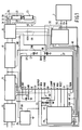
- each of the elements shown in Figure 1 correspond to those of a ballast means disclosed in European Patent Application Serial No. 399.613.
- the ballast means including the following elements of European Patent Application Serial No. 399.613 namely, input rectifier circuit 32, pre-conditioner circuit 28, DC-AC converter circuit 24, output circuit 20, fluorescent lamps 11 and 12, voltage supply 40, control circuit 36, signal applying circuit 112 and dimming interface circuit 110 correspond respectively to input rectifier circuit 13, preconditioner circuit 15, DC-AC converter circuit 17, output circuit 19, fluorescent lamps 21 and 23, voltage supply 25, control circuit 27, signal applying circuit 29 and dimming interface circuit 30 of this application.
- the operation of the ballast means is described in European Patent Application Serial No. 399.613.
- the light output of fluorescent lamps 21 and 23 is controllable by means of the voltage present between terminal 113 and terminal 114 of dimming interface circuit 30.
- Light sensing circuit 2 receives its power for operation from the ballast means shown in Figure 1 from terminals 113 and 114.
- Light sensing circuit 2 comprises a light sensor LS connected between line 114 and one end of a capacitor C. The other end of capacitor C is connected to terminal 113. The one end of capacitor C is also connected to the base of NPN transistor Q1 which acts as a first stage amplifier. The emitter of transistor Q1 is connected to line 114. The base of transistor Q1 is also connected to one end of a variable resistor R whose other end is connected to line 113.
- the collector of transistor Q1 is connected to one end of a resistor R c whose other end is connected to line 113.
- the one end of resistor R c is also connected to the base of PNP transistor Q2.
- Transistor Q2 serves as the second stage amplifier of the disclosed control circuit. It acts as a current sink.
- the emitter of this transistor is connected to line 113 while its collector is connected to line 114.
- a zener diode is also connected across lines 113 and 114 to protect against overvoltages being applied across those lines.
- light sensor LS In controlling the backlighting of a liquid crystal display, light sensor LS is placed in a position where it can only sense light incident on the display, or at least a part thereof. It should be so located that the backlighting does not strike it. In response to the light striking light sensor LS it controls the operation of transistor Q1 in accordance with the bias established by variable resistor R. Transistor Q1 in turn, in conjunction with biasing resistor R c controls the operation of transistor Q2. In operation, the less incident light that strikes light sensor LS the more current transistor Q1 conducts. As a result transistor Q2 sinks more current between terminals 113 and 114. This causes interface circuit 30 to lower the luminescence of lamps 21 and 23. As incident light at the display increases light sensor LS causes transistor Q1 to conduct less current accordingly. This causes transistor Q2 to sink less current between lines 113 and 114 and consequently, interface circuit 30 operates to cause lamps 21 and 23 to increase their luminescence.
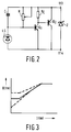
- Figure 3 shows the controlled light output of fluorescent lamps 0, expressed in lumen as a function of the incident light on the light sensor I, also expressed in lumen.
- a curve in solid line is the presently desired method of operating such liquid crystal display backlighting lamps.
- a threshold of light is provided even without light incident on light sensor LS. This remains somewhat constant for an increase in incident light and then increases in accordance with the slope of the solid line curve until it reaches a maximum, whereupon the controlled lamp light output remains constant again regardless of increased light incident on the display.
- the upper dotted line shows a similar method of controlling the lamp light output except it starts at a higher threshold and has a less steep slope from that higher threshold to the maximum light output.
- the lower dotted curve starts at a lower threshold but increases continuously until it gets to the maximum lamp output.
Landscapes
- Circuit Arrangements For Discharge Lamps (AREA)
- Liquid Crystal (AREA)
- Liquid Crystal Display Device Control (AREA)
- Discharge-Lamp Control Circuits And Pulse- Feed Circuits (AREA)
Claims (8)
- Leuchtstofflampenregler zum Betreiben wenigstens einer Leuchtstofflampe (21, 23) mit folgenden Elementen:- einer Lichtsensorschaltung (2) zum Erzeugen eines Signals zur Darstellung des Umgebungslichtstärke, mit- einem Lichtsensor (LS),- einem Erststufenverstärker (Q1), der mit dem Sensor gekoppelt ist,- einem Zweistufenverstärker (Q2), der mit einem Ausgang des Erststufenverstärkers verbunden ist, und- zwei Klemmen (113, 114) in Verbindung mit dem Zweistufenverstärker,- einem Vorschaltgerät mit einer Lichtregelschaltung (30), die mit der Lichtsensorschaltung über die Klemmen verbunden ist, um den Lichtausgang der Leuchtstofflampe zu erhöhen, wenn das Signal eine Erhöhung der Umgebungslichtstärke angibt, wobei das Signal zwischen den Klemmen und der Sensorschaltung vorhanden ist, die Leistung aus dem Vorschaltgerät über die Klemmen empfängt.
- Leuchtstofflampenregler nach Anspruch 1, worin der Erststufenverstärker einen npn-Transistor (Q₁) enthält.
- Leuchtstofflampenregeler nach Anspruch 1, oder 2, worin der Zweistufenverstärker einen pnp-Transistor (Q₂) enthält.
- Leuchtstofflampenregler nach Anspruch 1, 2 oder 3, worin die Lichtsensorschaltung Mittel (R) zum wesentlichen Konstanthalten des Lichtausgangs der Leuchtstofflampe enthält, wenn die Umgebungslichtstärke einen Schwellenpegel unterschreitet.
- Lichtsensorschaltung (2) zum Erzeugen eines Signals zur Darstellung der Umgebungslichtstärke, mit folgenden Elementen- einem Lichtsensor (LS),- einem Erststufenverstärker (Q₁), der mit dem Sensor gekoppelt ist,- einem Zweistufenverstärker (Q₂(, der mit einem Ausgang des Erststufenverstärkers verbunden ist, und- zwei Klemmen (113, 114) in Verbindung mit dem Zweistufenverstärker zum Verbinden eines Vorschaltgeräts zum Betreiben wenigstens einer Leuchtstofflampe, wobei das Vorschaltgerät eine Lichtregelschaltung (30) enthält, und den Lichtausgang der Leuchtstofflampe erhöht, wenn das Signal einen Anstieg in der Umgebungslichtstärke im Betrieb anzeigt, wobei das Signal zwischen den Klemmen und der Lichtsensorschaltung vorhanden ist, die Leistung aus dem Vorschaltgerät über die Klemmen empfängt, wenn die Lichtsensorschaltung mit dem Vorschaltgerät verbunden ist.
- Lichtsensorschaltung nach Anspruch 5, worin der Erststufenverstärker einen npn-Transistor (Q₁) enthält.
- Lichtsensorschaltung nach Anspruch 5 oder 6, worin der Zweistufenverstärker einen pnp-Transistor (Q₂) enthält.
- Lichtsensorschaltung nach Anspruch 5, 6 oder 7, mit Mitteln (R) zum wesentlichen Konstanthalten des Lichtausgangs der Leuchtstofflampe, wenn die Umgebungslichtstärke einen Schwellenpegel unterschreitet.
Applications Claiming Priority (2)
| Application Number | Priority Date | Filing Date | Title |
|---|---|---|---|
| US07/510,508 US5118992A (en) | 1990-04-17 | 1990-04-17 | Fluorescent lamp controlling arrangement |
| US510508 | 1990-04-17 |
Publications (2)
| Publication Number | Publication Date |
|---|---|
| EP0453030A1 EP0453030A1 (de) | 1991-10-23 |
| EP0453030B1 true EP0453030B1 (de) | 1995-09-20 |
Family
ID=24031037
Family Applications (1)
| Application Number | Title | Priority Date | Filing Date |
|---|---|---|---|
| EP91200862A Expired - Lifetime EP0453030B1 (de) | 1990-04-17 | 1991-04-12 | Anordnung zur Regelung von einem Leuchtstoffrohr |
Country Status (8)
| Country | Link |
|---|---|
| US (1) | US5118992A (de) |
| EP (1) | EP0453030B1 (de) |
| JP (1) | JP3179125B2 (de) |
| KR (1) | KR100229559B1 (de) |
| CN (1) | CN1039766C (de) |
| CA (1) | CA2040452A1 (de) |
| DE (1) | DE69113096T2 (de) |
| HK (1) | HK170796A (de) |
Cited By (1)
| Publication number | Priority date | Publication date | Assignee | Title |
|---|---|---|---|---|
| US8212741B2 (en) | 2005-06-01 | 2012-07-03 | Koninklijke Philips Electronics N.V. | Dual display device |
Families Citing this family (7)
| Publication number | Priority date | Publication date | Assignee | Title |
|---|---|---|---|---|
| US5436532A (en) * | 1993-03-26 | 1995-07-25 | Rockwell International Corporation | Fluorescent lamp with improved efficiency |
| GB2312121A (en) * | 1996-04-13 | 1997-10-15 | Thomson Multimedia Sa | LCD television projector with lamp aging compensation |
| US7758234B1 (en) | 2005-10-03 | 2010-07-20 | Pass & Seymour, Inc. | Electrical lighting device |
| US7064492B1 (en) * | 2003-10-10 | 2006-06-20 | National Semiconductor Corporation | Automatic ambient light compensation for display backlighting |
| US6969955B2 (en) * | 2004-01-29 | 2005-11-29 | Axis Technologies, Inc. | Method and apparatus for dimming control of electronic ballasts |
| CN101064983B (zh) * | 2006-04-27 | 2010-12-15 | 马士科技有限公司 | 紧凑型光控荧光灯及其光控电路 |
| US8148915B2 (en) * | 2009-09-01 | 2012-04-03 | Inergy Technology Inc. | Electronic ballast device and operation method thereof |
Citations (1)
| Publication number | Priority date | Publication date | Assignee | Title |
|---|---|---|---|---|
| EP0416697A2 (de) * | 1989-09-05 | 1991-03-13 | Philips Electronics North America Corporation | Steuerschaltung für einen Dimmer |
Family Cites Families (15)
| Publication number | Priority date | Publication date | Assignee | Title |
|---|---|---|---|---|
| GB987077A (en) * | 1962-08-23 | 1965-03-24 | Standard Telephones Cables Ltd | Lamp control |
| US3345536A (en) * | 1964-02-21 | 1967-10-03 | Wagner Electric Corp | Photoelectric control circuit |
| US3659148A (en) * | 1970-12-16 | 1972-04-25 | Nasa | Lamp modulator |
| US3777225A (en) * | 1972-04-24 | 1973-12-04 | L Dixon | Low power light controlled switching device |
| US3904922A (en) * | 1973-11-19 | 1975-09-09 | Xerox Corp | Lamp control and lamp switch circuit |
| DE2426382A1 (de) * | 1974-05-31 | 1975-12-11 | Bbc Brown Boveri & Cie | Verkehrszeichen mit umfeldabhaengiger beleuchtung |
| US3970893A (en) * | 1974-11-27 | 1976-07-20 | Strand Century Incorporated | Apparatus for controlling the intensity of lights |
| US4114366A (en) * | 1976-08-02 | 1978-09-19 | Texas Instruments Incorporated | Digital brightness control system |
| US4210846A (en) * | 1978-12-05 | 1980-07-01 | Lutron Electronics Co., Inc. | Inverter circuit for energizing and dimming gas discharge lamps |
| US4464606A (en) * | 1981-03-25 | 1984-08-07 | Armstrong World Industries, Inc. | Pulse width modulated dimming arrangement for fluorescent lamps |
| JPS57185062A (en) * | 1981-05-08 | 1982-11-15 | Hitachi Ltd | Controller of light volume |
| US4663570A (en) * | 1984-08-17 | 1987-05-05 | Lutron Electronics Co., Inc. | High frequency gas discharge lamp dimming ballast |
| US4712923A (en) * | 1986-06-23 | 1987-12-15 | Martin Victor G | Electronic calendar and method for randomly selecting and displaying messages |
| DE3627134A1 (de) * | 1986-08-09 | 1988-02-11 | Philips Patentverwaltung | Verfahren und schaltungsanordnung zur helligkeits- und temperaturabhaenigen steuerung einer lampe, insbesondere zur beleuchtung einer lcd-anzeige |
| US5003230A (en) * | 1989-05-26 | 1991-03-26 | North American Philips Corporation | Fluorescent lamp controllers with dimming control |
-
1990
- 1990-04-17 US US07/510,508 patent/US5118992A/en not_active Expired - Lifetime
-
1991
- 1991-04-12 DE DE69113096T patent/DE69113096T2/de not_active Expired - Fee Related
- 1991-04-12 EP EP91200862A patent/EP0453030B1/de not_active Expired - Lifetime
- 1991-04-13 CN CN91102944A patent/CN1039766C/zh not_active Expired - Fee Related
- 1991-04-13 KR KR1019910005930A patent/KR100229559B1/ko not_active Expired - Fee Related
- 1991-04-15 CA CA002040452A patent/CA2040452A1/en not_active Abandoned
- 1991-04-15 JP JP10831291A patent/JP3179125B2/ja not_active Expired - Fee Related
-
1996
- 1996-09-12 HK HK170796A patent/HK170796A/en not_active IP Right Cessation
Patent Citations (1)
| Publication number | Priority date | Publication date | Assignee | Title |
|---|---|---|---|---|
| EP0416697A2 (de) * | 1989-09-05 | 1991-03-13 | Philips Electronics North America Corporation | Steuerschaltung für einen Dimmer |
Cited By (1)
| Publication number | Priority date | Publication date | Assignee | Title |
|---|---|---|---|---|
| US8212741B2 (en) | 2005-06-01 | 2012-07-03 | Koninklijke Philips Electronics N.V. | Dual display device |
Also Published As
| Publication number | Publication date |
|---|---|
| JPH04230734A (ja) | 1992-08-19 |
| CN1057750A (zh) | 1992-01-08 |
| KR100229559B1 (ko) | 1999-11-15 |
| HK170796A (en) | 1996-09-20 |
| JP3179125B2 (ja) | 2001-06-25 |
| KR910019480A (ko) | 1991-11-30 |
| DE69113096D1 (de) | 1995-10-26 |
| EP0453030A1 (de) | 1991-10-23 |
| DE69113096T2 (de) | 1996-04-18 |
| CN1039766C (zh) | 1998-09-09 |
| CA2040452A1 (en) | 1991-10-18 |
| US5118992A (en) | 1992-06-02 |
Similar Documents
| Publication | Publication Date | Title |
|---|---|---|
| US4464606A (en) | Pulse width modulated dimming arrangement for fluorescent lamps | |
| CA2024440C (en) | Dimmer control circuit | |
| EP0510751B1 (de) | Beleuchtungseinrichtung mit Leuchtstofflampen in Gebäuden | |
| US5581158A (en) | Lamp brightness control circuit with ambient light compensation | |
| JP2007516687A (ja) | 高効率オフライン線形電源 | |
| KR100210275B1 (ko) | 가스 방전 램프에 전력을 공급하기 위한 회로 | |
| KR101657474B1 (ko) | 주변 밝기에 따라 자동으로 조도가 조절되는 led 장치 | |
| EP0453030B1 (de) | Anordnung zur Regelung von einem Leuchtstoffrohr | |
| JPH04259798A (ja) | けい光ランプ照明装置 | |
| EP0432845B1 (de) | Methode zur Steuerung von Dimmern für Entladungslampen und Schaltung zur Erzeugung solch einer Steuerung | |
| JP2600712Y2 (ja) | ソーラーランプ | |
| EP1387489A1 (de) | Pulsbreitenmodulationsschaltung und Beleuchtungseinrichtung | |
| CN220570702U (zh) | 一种降低led光衰的驱动电路 | |
| JP2020201774A (ja) | 照明用電源およびその保護回路 | |
| US20040183468A1 (en) | Variable frequency half bridge driver | |
| JPH0220110Y2 (de) | ||
| KR970003191Y1 (ko) | 웨이퍼 마킹 장비의 운전램프 구동회로 | |
| CA1228115A (en) | Energizing circuit for fluorescent lamps | |
| JPS641759Y2 (de) | ||
| KR950002416B1 (ko) | 펄스신호제어 조광회로 | |
| KR920003131Y1 (ko) | 전자식 형광등 안정기 | |
| JPH0696891A (ja) | 放電灯点灯装置 | |
| JPH10307557A (ja) | バッテリーインジケーターを兼用したパワーledの駆動回路 | |
| JPH11176589A (ja) | 蛍光管点灯装置 | |
| JPH088078A (ja) | 無電極放電灯点灯装置 |
Legal Events
| Date | Code | Title | Description |
|---|---|---|---|
| PUAI | Public reference made under article 153(3) epc to a published international application that has entered the european phase |
Free format text: ORIGINAL CODE: 0009012 |
|
| AK | Designated contracting states |
Kind code of ref document: A1 Designated state(s): BE DE FR GB IT NL |
|
| 17P | Request for examination filed |
Effective date: 19920422 |
|
| 17Q | First examination report despatched |
Effective date: 19940325 |
|
| GRAA | (expected) grant |
Free format text: ORIGINAL CODE: 0009210 |
|
| AK | Designated contracting states |
Kind code of ref document: B1 Designated state(s): BE DE FR GB IT NL |
|
| REF | Corresponds to: |
Ref document number: 69113096 Country of ref document: DE Date of ref document: 19951026 |
|
| ITF | It: translation for a ep patent filed | ||
| ET | Fr: translation filed | ||
| PG25 | Lapsed in a contracting state [announced via postgrant information from national office to epo] |
Ref country code: BE Effective date: 19960430 |
|
| PLBE | No opposition filed within time limit |
Free format text: ORIGINAL CODE: 0009261 |
|
| STAA | Information on the status of an ep patent application or granted ep patent |
Free format text: STATUS: NO OPPOSITION FILED WITHIN TIME LIMIT |
|
| 26N | No opposition filed | ||
| BERE | Be: lapsed |
Owner name: PHILIPS ELECTRONICS N.V. Effective date: 19960430 |
|
| PG25 | Lapsed in a contracting state [announced via postgrant information from national office to epo] |
Ref country code: NL Effective date: 19961101 |
|
| NLV4 | Nl: lapsed or anulled due to non-payment of the annual fee |
Effective date: 19961101 |
|
| REG | Reference to a national code |
Ref country code: FR Ref legal event code: CD |
|
| REG | Reference to a national code |
Ref country code: GB Ref legal event code: 746 Effective date: 20010529 |
|
| REG | Reference to a national code |
Ref country code: FR Ref legal event code: D6 |
|
| REG | Reference to a national code |
Ref country code: GB Ref legal event code: IF02 |
|
| PGFP | Annual fee paid to national office [announced via postgrant information from national office to epo] |
Ref country code: FR Payment date: 20020426 Year of fee payment: 12 |
|
| PGFP | Annual fee paid to national office [announced via postgrant information from national office to epo] |
Ref country code: GB Payment date: 20020430 Year of fee payment: 12 |
|
| PGFP | Annual fee paid to national office [announced via postgrant information from national office to epo] |
Ref country code: DE Payment date: 20020625 Year of fee payment: 12 |
|
| PG25 | Lapsed in a contracting state [announced via postgrant information from national office to epo] |
Ref country code: GB Free format text: LAPSE BECAUSE OF NON-PAYMENT OF DUE FEES Effective date: 20030412 |
|
| PG25 | Lapsed in a contracting state [announced via postgrant information from national office to epo] |
Ref country code: DE Free format text: LAPSE BECAUSE OF NON-PAYMENT OF DUE FEES Effective date: 20031101 |
|
| GBPC | Gb: european patent ceased through non-payment of renewal fee |
Effective date: 20030412 |
|
| PG25 | Lapsed in a contracting state [announced via postgrant information from national office to epo] |
Ref country code: FR Free format text: LAPSE BECAUSE OF NON-PAYMENT OF DUE FEES Effective date: 20031231 |
|
| REG | Reference to a national code |
Ref country code: FR Ref legal event code: ST |
|
| PG25 | Lapsed in a contracting state [announced via postgrant information from national office to epo] |
Ref country code: IT Free format text: LAPSE BECAUSE OF NON-PAYMENT OF DUE FEES;WARNING: LAPSES OF ITALIAN PATENTS WITH EFFECTIVE DATE BEFORE 2007 MAY HAVE OCCURRED AT ANY TIME BEFORE 2007. THE CORRECT EFFECTIVE DATE MAY BE DIFFERENT FROM THE ONE RECORDED. Effective date: 20050412 |