EP0453039B1 - Elektronenstrahlröhre mit Elektronenstrahlerzeugungssystem - Google Patents
Elektronenstrahlröhre mit Elektronenstrahlerzeugungssystem Download PDFInfo
- Publication number
- EP0453039B1 EP0453039B1 EP91200884A EP91200884A EP0453039B1 EP 0453039 B1 EP0453039 B1 EP 0453039B1 EP 91200884 A EP91200884 A EP 91200884A EP 91200884 A EP91200884 A EP 91200884A EP 0453039 B1 EP0453039 B1 EP 0453039B1
- Authority
- EP
- European Patent Office
- Prior art keywords
- support
- clamping member
- cathode ray
- ray tube
- electrode
- Prior art date
- Legal status (The legal status is an assumption and is not a legal conclusion. Google has not performed a legal analysis and makes no representation as to the accuracy of the status listed.)
- Expired - Lifetime
Links
- 239000000463 material Substances 0.000 claims description 10
- 238000004519 manufacturing process Methods 0.000 claims description 4
- 238000003825 pressing Methods 0.000 claims description 4
- 238000010438 heat treatment Methods 0.000 claims description 2
- 238000000034 method Methods 0.000 claims description 2
- 239000012777 electrically insulating material Substances 0.000 abstract 1
- 238000010894 electron beam technology Methods 0.000 description 8
- OAICVXFJPJFONN-UHFFFAOYSA-N Phosphorus Chemical compound [P] OAICVXFJPJFONN-UHFFFAOYSA-N 0.000 description 6
- 238000010276 construction Methods 0.000 description 3
- 230000036962 time dependent Effects 0.000 description 2
- 208000010392 Bone Fractures Diseases 0.000 description 1
- 206010017076 Fracture Diseases 0.000 description 1
- 230000002411 adverse Effects 0.000 description 1
- 238000001816 cooling Methods 0.000 description 1
- 239000011521 glass Substances 0.000 description 1
- 230000012447 hatching Effects 0.000 description 1
- 230000035945 sensitivity Effects 0.000 description 1
Images

Classifications
-
- H—ELECTRICITY
- H01—ELECTRIC ELEMENTS
- H01J—ELECTRIC DISCHARGE TUBES OR DISCHARGE LAMPS
- H01J9/00—Apparatus or processes specially adapted for the manufacture, installation, removal, maintenance of electric discharge tubes, discharge lamps, or parts thereof; Recovery of material from discharge tubes or lamps
- H01J9/02—Manufacture of electrodes or electrode systems
- H01J9/18—Assembling together the component parts of electrode systems
-
- H—ELECTRICITY
- H01—ELECTRIC ELEMENTS
- H01J—ELECTRIC DISCHARGE TUBES OR DISCHARGE LAMPS
- H01J29/00—Details of cathode-ray tubes or of electron-beam tubes of the types covered by group H01J31/00
- H01J29/46—Arrangements of electrodes and associated parts for generating or controlling the ray or beam, e.g. electron-optical arrangement
- H01J29/82—Mounting, supporting, spacing, or insulating electron-optical or ion-optical arrangements
Definitions
- the invention relates to a cathode ray tube comprising an electron gun having at least one electrode and at least one support of a material which can be softened, the support and the electrode being interconnected.
- a cathode ray tube is known from United States Patent Specification US-A-4,096,408.
- a description is given of a cathode ray tube comprising an electron gun having electrodes and supports. The supports and the electrodes are interconnected.
- Cathode ray tubes are used, inter alia, in display devices such as, for example, colour televisions, oscilloscopes, projection televisions and DGD (Data Graphic Display) apparatuses.
- display devices such as, for example, colour televisions, oscilloscopes, projection televisions and DGD (Data Graphic Display) apparatuses.
- DGD Data Graphic Display
- Vibrations can be caused by external influences, for example by sound vibrations which are transmitted to the electron gun or by conditions inside the electron gun, for example varying electric voltages between the electrodes. Vibrations disturb the mutual positioning of the electrodes, thus causing the position and intensity of the electron beam(s) generated by the electron gun to be subject to time-dependent variations. As a result thereof, images produced by the electron beam(s) on, for example, a display screen of the cathode ray tube are subject to time-dependent variations which adversely affect picture quality.
- One of the objects of the invention is to provide a cathode ray tube of the type mentioned in the opening paragraph, which exhibits an improved microphonic behaviour.
- the cathode ray tube according to the invention is characterized in that the electrode is provided with a serrated clamping member in which the support is held, the serrations in the clamping member clamping said support at the periphery of the support.
- one or more projections are pressed into a support after which the projection(s), which has (have) expanded as a result of the heat, cool(s) down and become(s) clamped in the support.
- the invention relates to changing the electrode such that during the pressing together of the support and the electrode, the support can be pressed into the serrated clamping member.
- Said clamping member encloses a large portion of the circumference of the support and the electrode is fixed at the periphery of the support by means of the serrations in the clamping member.
- connection between the electrode and the support is obtained.
- the connection has a larger stability.
- the stability of the support is larger because the serrations do not penetrate the support as deeply as the known projections.
- the shape of the support preferably corresponds to that of the clamping member.
- the bottom of the clamping member is smaller or equally large as the front side of the clamping member and the serrations are provided between the bottom and the front side of said clamping member.
- a hillock is formed on the bottom of the clamping member, which causes the material of the support to be urged to serrations located close to the bottom of the clamping member during the pressing together of the electrode and the support. This results in an improved connection between the electrodes and the support.
- the serrations are formed such that the distance between the serrations, as a function of the distance to the bottom of the clamping member in a direction transverse to the bottom, exhibits local minima.
- the electron gun comprises more than one electrode and more than one support.
- the invention also relates to a method of manufacturing a cathode ray tube, in which electrodes of an electron gun and supports of softenable material are interconnected in a manufacturing step by heating the supports to the softening temperature of the support material and pressing the supports and the electrodes against each other, such that the support is pressed into a serrated clamping member formed at the electrode, after which the assembly of electrodes and supports is left to cool.
- forces are exerted on the material of the support with a component transverse to the serrations, while the supports and the electrodes are being pressed together.
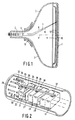
- Fig. 1 is a sectional view of a cathode ray tube comprising an electron gun.
- a colour display tube of the "in-line" type is shown.
- An electron gun 5 is provided in the neck 4 of a glass evacuated envelope 1 which is composed of a display window 2, a cone 3 and a neck 4, said electron gun generating three electron beams 6, 7 and 8 whose axes are located in the plane of the drawing.
- the axis of the central electron beam 7 initially coincides with the tube axis 9.
- a large number of triads of phosphor elements 10 are provided on the inside of the display window 2. Said elements may consist of, for example, lines or dots.
- the display window contains linear elements.
- Each triad contains a line consisting of a phosphor luminescing in green, a line consisting of a phosphor luminescing in blue and a line consisting of a phosphor luminescing in red. Said phosphor lines extend transversely to the plane of the drawing.
- a shadow mask 11 having a large number of apertures 12 for passing the electron beams 6, 7 and 8 which each impinge only on phosphor lines of one colour.
- the three coplanar electron beams are deflected by the deflection coil system 13.
- Fig. 2 is a partly perspective elevational view of an electron gun 20.
- the electron gun comprises a common control electrode 21 in which three cathodes 22, 23 and 24 are secured. Said common control electrode 21 is secured to supports 26 by means of securing members 25.
- the electron gun 20 further comprises a common plate-shaped electrode 27 which is connected to the supports through parts 28.
- the three coplanar electron beams are focused by a common electrode 29, which is provided with securing members 30, and a common electrode 31 which is provided with securing members 32.
- the supports are connected to feed-through pins 35 by means of supporting brackets 33 having securing members 34.
- the electron gun 20 comprises two supports. The construction shown shall not be interpreted limiting the scope of the invention.
- the electron gun may comprise more than two supports.
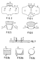
- Fig. 3 is a top view of an electrode suitable for use in a known cathode ray tube.
- Said electrode in the present example a plate-shaped electrode 27, is provided with projections 28 having a dovetailed recess. Said projections are pressed into the supports 26.
- the electrode comprises apertures 36 for passing the electron beams.
- Electrode 40 comprises a clamping member 41 having serrations 42 between the bottom and the front at two facing sides of the clamping member.
- the support 26 is clamped by said serrations.
- an improved connection between the electrodes and the supports is obtained.
- the stability of the connection has increased.
- the stability of the support has increased because the serrations do not penetrate the support as far as the projections. This results in a more stable construction and, hence, an improved microphonic behaviour of the electron gun.
- the electrode 40 is more rigid than the electrode 27 as a result of the shape of the clamping member, which brings about an improved microphonic behaviour.
- the bottom of the clamping member has a length D1
- the front side of the clamping member has a length D2.
- the bottom of the clamping member is smaller than the front side and the serrations are located between the bottom and the front side of the clamping member.
- a hillock 43 is formed on the bottom of the clamping member. This is a means of exerting forces on the support which urge the material of the support to the serrations, while the support and the electrode are being pressed together. By virtue hereof, the effectiveness of the serrations close to the bottom are improved.
- Figs. 5 and 6 are top views of further examples of clamping members 41 of electrodes suitable for use in a cathode ray tube according to the invention.
- clamping member 41 forms an at least substantially U-shaped recess.
- clamping member 41 forms a recess in the form of a half arc.
- Figs. 5 and 6 are also sectional views of supports 26 and 61. The shapes of said supports are adapted to the shape of the clamping member.
- Fig. 7 is a sectional view of a support 26.
- said support 26 there are secured two electrodes, electrode 27 as shown in Fig. 3 having projection 28, and electrode 40 as shown in Fig. 4 having clamping member 41. It has been found that during interconnecting the electrodes and the support, said support exhibits less deformation next to electrode 40 than next to electrode 27.
- Fig. 7 shows how the use of the known electrode causes the support to bulge in the immediate vicinity of the electrode 27, which does not happen, or to a much lesser extent, in the direct vicinity of the electrode 40. As a result thereof, fewer stresses occur in the carrier. The risk of fracture is reduced and the accuracy with which the electrode is positioned is improved. In addition, the charging of the support is reduced.
- Figs. 8a, 8b and 8c illustrate a further advantage of the invention.
- Supports 26 and 81 are shown in section.
- the hatching in Fig. 8a indicates the portion 81 which has to be heated to at least the softening temperature when the support and the electrode 27 are interconnected.
- Fig. 8b shows the portion 81 which has to be heated to the softening temperature when an electrode 40 having a clamping member 41, as shown in Fig. 4, is used.
- This is a smaller portion than portion 81 in figure 8a.
- Fig. 8c shows a support whose shape is adapted to that of the clamping member shown in Fig. 6. In this case, the portion 83 to be heated to the softening temperature is even smaller than in Fig. 8b.
- Fig. 9a is a top view of a clamping member 41 having serrations 42.
- the distance D between the serrations 42 varies as a function of x, in such a manner that for the points 44 the distance D exhibits a local minimum. This is graphically shown in Figs. 9b and 9c. After cooling, the clamping member clamps the support through the points 44 (Fig.9b) or 44′ (Fig. 9c).
- the clamping member may be formed by two plate-shaped elements which are serrated on the inside as shown in Figs. 10a and 10b.
- the connection can be further improved.
- Figs. 10a and 10b are perspective and top views, respectively, of a box-shaped electrode 100.
- the top surface 101 there are provided apertures 102, 103 and 104.
- a bracket 105 is provided at a side wall. Said bracket 105 contains two plate-shaped elements 106 and 107, the facing sides of which are provided with serrations 108.
- the cathode ray tube may be a monochrome display tube, for example a projection cathode ray tube.
- the cathode ray tube may be an oscilloscope cathode ray tube or any other type of cathode ray tube.
- clamping member is to be understood to mean, inter alia, a straight or conical embracing member such as, for example, a recess as shown in Figs. 4, 5, 6 and 9a or, for example, a duct as shown in Figs. 10a and 10b.
- Standard clamping member is to be understood to mean herein an embracing element having two facing sides which are provided with serrations. The support is clamped in the clamping member by means of said serrations.
Landscapes
- Engineering & Computer Science (AREA)
- Manufacturing & Machinery (AREA)
- Electron Sources, Ion Sources (AREA)
- Electrodes For Cathode-Ray Tubes (AREA)
- Lasers (AREA)
- Vessels, Lead-In Wires, Accessory Apparatuses For Cathode-Ray Tubes (AREA)
Claims (9)
- Elektronenstrahlröhre mit einem Elektronenstrahlerzeugungssystem (5, 20) mit wenigstens einer Elektrode (21, 27, 29, 31, 40) und wenigstens einem Träger (26) aus einem erweichbaren Material, wobei der Träger und die Elektrode miteinander verbunden sind, dadurch gekennzeichnet, daß die Elektrode mit einem gezahnten Klemmelement (41) versehen ist, in dem der Träger festgehalten wird, wobei die Zähne (42) im Klemmelement den Träger am Umfang des Trägers einklemmen.
- Elektronenstrahlröhre nach Anspruch 1, dadurch gekennzeichnet, daß die Form des Trägers der Form des Klemmelements entspricht.
- Elektronenstrahlröhre nach Anspruch 1 oder 2, dadurch gekennzeichnet, daß der Boden des Klemmelements kleiner oder gleich groß wie die Vorderseite des Klemmelements ist, und daß die Zähne sich zwischen dem Boden und der Vorderseite des Klemmelements befinden.
- Elektronenstrahlröhre nach Anspruch 1, 2 oder 3, dadurch gekenn zeichnet, daß eine Oberflächenunebenheit (43) am Boden des Klemmelements gebildet wird.
- Elektronenstrahlröhre nach Anspruch 1, 2, 3 oder 4, dadurch gekenn zeichnet, daß die Zähne derart gebildet sind, daß der Abstand zwischen den Zähnen abhängig vom Abstand zum Boden des Klemmelements in einer Richtung quer zum Boden örtliche Mindestwerte (44, 44′) aufweisen.
- Elektronenstrahlröhre nach Anspruch 1, 2, 3, 4 oder 5, dadurch gekenn zeichnet, daß das Klemmelement aus zwei plattenförmigen Elementen (106, 107) besteht, deren einander zugewandte Seiten mit Zähnen (108) versehen sind.
- Elektronenstrahlröhre nach Anspruch 1, 2, 3, 4, 5, 6 oder 7 ?, dadurch gekennzeichnet, daß das Elektronenstrahlerzeugungssystem mehr als eine Elektrode und mehr als einen Träger enthält.
- Verfahren zum Herstellen einer Elektronenstrahlröhre, in dem Elektroden (40) eines Strahlerzeugungssystems (5, 20) und Träger (26) aus erweichbarem Material in einem Herstellungsschritt durch Erwärmen der Träger auf die Erweichungstemperatur des Trägermaterials und durch Andrücken der Träger und der Elektroden nacheinander hin miteinander derart verbunden werden, daß der Träger an seinem Umfang in ein gezahntes an der Elektrode gebildetes Klemmelement angedrückt wird, wonach die Gruppe von Elektroden und Trägern zum Abkühlen belassen wird.
- Verfahren nach Anspruch 8, dadurch gekennzeichnet, daß auf das Material des Träges mit einer Komponente quer zu den Zähnen Kräfte ausgeübt werden, während die Träger und die Elektroden aneinander gedrückt werden.
Applications Claiming Priority (2)
| Application Number | Priority Date | Filing Date | Title |
|---|---|---|---|
| NL9000943A NL9000943A (nl) | 1990-04-20 | 1990-04-20 | Kathodestraalbuis met elektronenkanon. |
| NL9000943 | 1990-04-20 |
Publications (2)
| Publication Number | Publication Date |
|---|---|
| EP0453039A1 EP0453039A1 (de) | 1991-10-23 |
| EP0453039B1 true EP0453039B1 (de) | 1995-11-29 |
Family
ID=19856970
Family Applications (1)
| Application Number | Title | Priority Date | Filing Date |
|---|---|---|---|
| EP91200884A Expired - Lifetime EP0453039B1 (de) | 1990-04-20 | 1991-04-15 | Elektronenstrahlröhre mit Elektronenstrahlerzeugungssystem |
Country Status (6)
| Country | Link |
|---|---|
| US (1) | US5140218A (de) |
| EP (1) | EP0453039B1 (de) |
| JP (1) | JP3152447B2 (de) |
| AT (1) | ATE130961T1 (de) |
| DE (1) | DE69114894T2 (de) |
| NL (1) | NL9000943A (de) |
Families Citing this family (4)
| Publication number | Priority date | Publication date | Assignee | Title |
|---|---|---|---|---|
| BE1007285A3 (nl) * | 1993-07-13 | 1995-05-09 | Philips Electronics Nv | Kathodestraalbuis. |
| CN1096098C (zh) * | 1995-12-22 | 2002-12-11 | 皇家菲利浦电子有限公司 | 包括具有折叠管形部件的电子枪的彩色阴极射线管 |
| JP2001307654A (ja) * | 2000-04-20 | 2001-11-02 | Toshiba Corp | カラー陰極線管 |
| JP2001345696A (ja) | 2000-05-30 | 2001-12-14 | Oki Electric Ind Co Ltd | チューニング回路 |
Family Cites Families (3)
| Publication number | Priority date | Publication date | Assignee | Title |
|---|---|---|---|---|
| US4096408A (en) * | 1976-01-28 | 1978-06-20 | Zenith Radio Corporation | Unitized in-line electron gun having stress-absorbing electrode supports |
| US4649317A (en) * | 1985-08-27 | 1987-03-10 | Rca Corporation | Multibeam electron gun having means for supporting a screen grid electrode relative to a main focusing lens |
| NL8701212A (nl) * | 1987-05-21 | 1988-12-16 | Philips Nv | Werkwijze voor het bevestigen van elektroden van een elektronenkanon aan dragers. |
-
1990
- 1990-04-20 NL NL9000943A patent/NL9000943A/nl not_active Application Discontinuation
-
1991
- 1991-04-08 US US07/682,802 patent/US5140218A/en not_active Expired - Fee Related
- 1991-04-15 EP EP91200884A patent/EP0453039B1/de not_active Expired - Lifetime
- 1991-04-15 AT AT91200884T patent/ATE130961T1/de not_active IP Right Cessation
- 1991-04-15 DE DE69114894T patent/DE69114894T2/de not_active Expired - Fee Related
- 1991-04-18 JP JP11214091A patent/JP3152447B2/ja not_active Expired - Fee Related
Also Published As
| Publication number | Publication date |
|---|---|
| DE69114894D1 (de) | 1996-01-11 |
| JP3152447B2 (ja) | 2001-04-03 |
| DE69114894T2 (de) | 1996-07-04 |
| US5140218A (en) | 1992-08-18 |
| EP0453039A1 (de) | 1991-10-23 |
| JPH04230936A (ja) | 1992-08-19 |
| NL9000943A (nl) | 1991-11-18 |
| ATE130961T1 (de) | 1995-12-15 |
Similar Documents
| Publication | Publication Date | Title |
|---|---|---|
| CA1206513A (en) | Cathode-ray tube | |
| EP0019975B1 (de) | Farbbildröhre | |
| EP0453039B1 (de) | Elektronenstrahlröhre mit Elektronenstrahlerzeugungssystem | |
| EP0295732B1 (de) | Verfahren zum Herstellen einer Elektronenkanone | |
| US5932957A (en) | Cathode-ray tube having detentioning rod assembly for a tension mask frame | |
| EP0889500A1 (de) | Farbbildröhre mit einer in-line Elektronenkanone | |
| US6271624B1 (en) | Cathode ray tube having a fag with spring holder | |
| US4992698A (en) | Color picture tube including an electron gun with an electrode having an optimized attachment means | |
| US6048240A (en) | Method of manufacturing a cathode ray tube | |
| US4082977A (en) | Electron gun for cathode ray tube detachable from base support | |
| JP2991446B2 (ja) | 電子銃部品及びその製造方法 | |
| US6580210B1 (en) | Method of manufacturing an electron gun, electron gun, display device with such an electron gun, and sub-assembly for use in such an electron gun | |
| HK1004029B (en) | Color picture tube including an electron gun with an electrode having an optimized attachment means | |
| US6215238B1 (en) | Cathode ray tube, electron gun for a cathode ray tube, method for manufacturing an electron gun, parts used in method for manufacturing an electron gun | |
| EP0755569B1 (de) | Eine in-line elektronenkanone enthaltende farbkathodenstrahlröhre | |
| EP1046182A1 (de) | Kathodenstrahlröhre mit ablenkeinheit | |
| EP0634773B1 (de) | Kathodenstrahlröhre | |
| KR0177946B1 (ko) | 칼라 음극선관용 전자총 | |
| KR20030035937A (ko) | 음극선관용 텐션 마스크 | |
| KR19990041262U (ko) | 칼라 음극선관용 전자총 | |
| JPS59149632A (ja) | カラ−受像管 | |
| JPH09190778A (ja) | カラー陰極線管 | |
| WO1999065053A1 (en) | Cathode ray tube comprising an electron gun | |
| JPS6199250A (ja) | 電子銃陰極構体 | |
| JPH0689670A (ja) | 陰極線管 |
Legal Events
| Date | Code | Title | Description |
|---|---|---|---|
| PUAI | Public reference made under article 153(3) epc to a published international application that has entered the european phase |
Free format text: ORIGINAL CODE: 0009012 |
|
| AK | Designated contracting states |
Kind code of ref document: A1 Designated state(s): AT DE ES FR GB |
|
| 17P | Request for examination filed |
Effective date: 19920422 |
|
| 17Q | First examination report despatched |
Effective date: 19941222 |
|
| GRAA | (expected) grant |
Free format text: ORIGINAL CODE: 0009210 |
|
| AK | Designated contracting states |
Kind code of ref document: B1 Designated state(s): AT DE ES FR GB |
|
| PG25 | Lapsed in a contracting state [announced via postgrant information from national office to epo] |
Ref country code: ES Free format text: THE PATENT HAS BEEN ANNULLED BY A DECISION OF A NATIONAL AUTHORITY Effective date: 19951129 Ref country code: AT Effective date: 19951129 |
|
| REF | Corresponds to: |
Ref document number: 130961 Country of ref document: AT Date of ref document: 19951215 Kind code of ref document: T |
|
| REF | Corresponds to: |
Ref document number: 69114894 Country of ref document: DE Date of ref document: 19960111 |
|
| ET | Fr: translation filed | ||
| PLBE | No opposition filed within time limit |
Free format text: ORIGINAL CODE: 0009261 |
|
| STAA | Information on the status of an ep patent application or granted ep patent |
Free format text: STATUS: NO OPPOSITION FILED WITHIN TIME LIMIT |
|
| 26N | No opposition filed | ||
| PGFP | Annual fee paid to national office [announced via postgrant information from national office to epo] |
Ref country code: GB Payment date: 19970401 Year of fee payment: 7 |
|
| PGFP | Annual fee paid to national office [announced via postgrant information from national office to epo] |
Ref country code: FR Payment date: 19970422 Year of fee payment: 7 |
|
| PGFP | Annual fee paid to national office [announced via postgrant information from national office to epo] |
Ref country code: DE Payment date: 19970624 Year of fee payment: 7 |
|
| PG25 | Lapsed in a contracting state [announced via postgrant information from national office to epo] |
Ref country code: GB Free format text: LAPSE BECAUSE OF NON-PAYMENT OF DUE FEES Effective date: 19980415 |
|
| PG25 | Lapsed in a contracting state [announced via postgrant information from national office to epo] |
Ref country code: FR Free format text: THE PATENT HAS BEEN ANNULLED BY A DECISION OF A NATIONAL AUTHORITY Effective date: 19980430 |
|
| GBPC | Gb: european patent ceased through non-payment of renewal fee |
Effective date: 19980415 |
|
| PG25 | Lapsed in a contracting state [announced via postgrant information from national office to epo] |
Ref country code: DE Free format text: LAPSE BECAUSE OF NON-PAYMENT OF DUE FEES Effective date: 19990202 |
|
| REG | Reference to a national code |
Ref country code: FR Ref legal event code: ST |