EP0453043A1 - Procédé pour nettoyer les parois d'un échangeur de chaleur et échangeur de chaleur comportant des moyens pour un tel nettoyage - Google Patents
Procédé pour nettoyer les parois d'un échangeur de chaleur et échangeur de chaleur comportant des moyens pour un tel nettoyage Download PDFInfo
- Publication number
- EP0453043A1 EP0453043A1 EP91200909A EP91200909A EP0453043A1 EP 0453043 A1 EP0453043 A1 EP 0453043A1 EP 91200909 A EP91200909 A EP 91200909A EP 91200909 A EP91200909 A EP 91200909A EP 0453043 A1 EP0453043 A1 EP 0453043A1
- Authority
- EP
- European Patent Office
- Prior art keywords
- walls
- heat exchanger
- particles
- fluid
- solid particles
- Prior art date
- Legal status (The legal status is an assumption and is not a legal conclusion. Google has not performed a legal analysis and makes no representation as to the accuracy of the status listed.)
- Granted
Links
- 238000004140 cleaning Methods 0.000 title claims abstract description 29
- 238000000034 method Methods 0.000 title claims description 11
- 239000002245 particle Substances 0.000 claims abstract description 105
- 239000007787 solid Substances 0.000 claims abstract description 65
- 239000012530 fluid Substances 0.000 claims abstract description 44
- 238000004821 distillation Methods 0.000 claims description 8
- 239000002184 metal Substances 0.000 claims description 6
- 239000011521 glass Substances 0.000 claims description 5
- 230000000630 rising effect Effects 0.000 claims description 5
- 238000007599 discharging Methods 0.000 claims description 3
- 238000005192 partition Methods 0.000 claims description 3
- 238000001704 evaporation Methods 0.000 claims description 2
- 238000007654 immersion Methods 0.000 claims description 2
- 239000013013 elastic material Substances 0.000 claims 1
- 239000007788 liquid Substances 0.000 description 6
- 230000001174 ascending effect Effects 0.000 description 3
- 238000009835 boiling Methods 0.000 description 3
- 239000000463 material Substances 0.000 description 3
- 230000003197 catalytic effect Effects 0.000 description 2
- 239000012535 impurity Substances 0.000 description 2
- 239000003208 petroleum Substances 0.000 description 2
- 230000002411 adverse Effects 0.000 description 1
- 239000000956 alloy Substances 0.000 description 1
- 229910045601 alloy Inorganic materials 0.000 description 1
- 230000003190 augmentative effect Effects 0.000 description 1
- 230000003851 biochemical process Effects 0.000 description 1
- 230000001413 cellular effect Effects 0.000 description 1
- 239000000919 ceramic Substances 0.000 description 1
- 238000001311 chemical methods and process Methods 0.000 description 1
- 230000000694 effects Effects 0.000 description 1
- 230000002255 enzymatic effect Effects 0.000 description 1
- 238000002474 experimental method Methods 0.000 description 1
- 238000011081 inoculation Methods 0.000 description 1
- 239000002054 inoculum Substances 0.000 description 1
- 230000002906 microbiologic effect Effects 0.000 description 1
- 230000000737 periodic effect Effects 0.000 description 1
- 230000001681 protective effect Effects 0.000 description 1
- 230000008929 regeneration Effects 0.000 description 1
- 238000011069 regeneration method Methods 0.000 description 1
- 230000000717 retained effect Effects 0.000 description 1
- 239000013535 sea water Substances 0.000 description 1
- 238000000926 separation method Methods 0.000 description 1
- 239000007921 spray Substances 0.000 description 1
Images


Classifications
-
- F—MECHANICAL ENGINEERING; LIGHTING; HEATING; WEAPONS; BLASTING
- F28—HEAT EXCHANGE IN GENERAL
- F28G—CLEANING OF INTERNAL OR EXTERNAL SURFACES OF HEAT-EXCHANGE OR HEAT-TRANSFER CONDUITS, e.g. WATER TUBES OR BOILERS
- F28G1/00—Non-rotary, e.g. reciprocated, appliances
- F28G1/12—Fluid-propelled scrapers, bullets, or like solid bodies
Definitions
- the invention relates to a method for cleaning at least one of the sides of the essentially vertical heat-transmitting walls between two fluids of a heat exchanger conveyed along opposite sides of said walls, and to a heat exchanger with means for said cleaning.
- heat exchangers must be understood in a wide sense, for example also including devices for carrying out under heat exchange all kinds of physical and chemical processes, such as catalytic or enzymatic processes, processes with inoculants or solid inoculation particles for grain growth, microbiological cleaning processes etc.
- a closed flow filling up the space between opposite walls, can run along the walls to be cleaned, or a film as in the case of film evaporators.
- the invention proposes achieving such cleaning by solid particles which clean the walls while moving along them, without interrupting the operation of the heat exchanger.
- the invention is intended for both heat exchangers with ascending and those with descending flow along the walls to be cleaned, the relevant particles in the first case being so large and heavy that, despite the upward medium flow, they can also in this case descend along said walls.
- All kinds of different materials can be used for the particles, for example of metal or glass.
- the metal selected is a metal or alloy which is not corroded by the heat-exchanging medium, and which does not have an adverse effect on the latter.
- a method of the type mentioned in the preamble is according to the invention characterized in that solid particles are introduced into a stream of fluid being essentially the same or being one phase of one of the fluids, which is undergoing heat exchange at that one side of said walls, said particles being smaller than the distance between opposite walls defining the flow of said fluid, in that said fluid with said particles is moved to a zone above said vertical walls into a part of a collection or distribution space for said fluid covering only part of the horizontal transverse plane of said vertical walls, said particles being collected below said vertical walls and discharged from the heat exchanger, which particles are so heavy and large that they move downwards along said walls and after discharge and possible cleaning are fed fully or partially back with said fluid stream to above said vertical walls, the flow of said particles with said fluid in each case being moved periodically to in each case a different part of said collection or distribution space covering a different horizontal transverse plane part above said vertical walls.
- a heat exchanger of the type referred to is according to the invention characterized in that means are fitted for bringing a partial stream of one of the fluids in a collection or distribution space above said walls with solid particles therein, smaller than the distance between opposite walls defining the flow of said fluid and heavy and large enough to move downwards along the side of those walls along which said fluid flows for heat exchange, with means for discharging said fluid with solid particles out of a distribution or collection space at the bottom of said walls and returning it fully or partially to said collection or distribution space, means being provided for taking the stream with solid particles in each case over a part of the total transverse surface of the vertical walls said collection or distribution space, and in which switch means are provided for periodically switching the feed of said particles to the distribution or collection space above said walls, in order to feed another part of said transverse surface with said particles.
- This system requires flow of the balls in the same direction as the fluid taking part in the heat exchange and the heat exchange flow is considerably impeded by these balls.
- the normal operation of the heat exchanger can go on during the cleaning with hardly any lessening of heat exchange or even augmenting thereof and with hardly any pressure loss. It is possible to have the particles move downwards both in a rising and in a downwardly directed stream of fluid.
- the invention makes it possible for a thorough cleaning to introduce a strong concentration (relatively large quantity) of such solid particles, while the heat exchange proceeds virtually unimpeded or is even reinforced.
- a strong concentration relatively large quantity
- said medium stream will become weaker over the part of said horizontal transverse plane where the particles are falling, but said stream, seeking the route of least resistance, is not impeded in the part of the heat exchanger not taking part in the cleaning at the time and, depending on the circumstances, may even become stronger, while no additional pump or fan capacity for the main stream of the medium is necessary.
- the heat exchanger of Figs. 1 and 2 has in a housing 1 a bottom tube plate 2 and a top tube plate 3, between which a number of vertical tubes 4 extend. Below the bottom plate 2 a distribution space 5 is formed, into which medium is fed through a pipe 6, which medium must flow upwards through the tubes 4 for heat exchange with a medium which is fed through the housing 1 between the tube plates around the tubes through inlets and outlets (not shown), and which moves, for example, in a zigzag path between inlet and outlet through horizontal partitions which grip round the tubes, but do not take up the whole horizontal surface of the housing 1, as known.
- the inlet of pipe 6 into space 5 is covered by a cap 7, in order to ensure better distribution of the inflowing medium and to prevent solid particles, to be described below, from entering said pipe 6.
- a collection space 8 Situated above the tube plate 3 is a collection space 8, from which the medium is discharged from the tubes through a pipe 9.
- tube plate 3 On top of the tube plate 3 is a set of plates which are combined to a star-shaped member 10, and which divide the horizontal cross-section of the housing, which in this case is of circular design, into, for example, six sectors 11.
- a discharge pipe 12 leading to a collector 13 for solid particles, and from there a pipe 14 leads to a distributor 15.
- the latter has a switch valve, for example rotating about a vertical axis (vide Fig. 6), which admits the incoming stream flowing through the pipe 14 to only one of the pipes 16 at any moment.
- Each of the six pipes 16 connects to a different sector 11 above tube plate 3.
- the pipes 16 are shown individually in Fig. 1, but not all drawn through to a sector, and are shown with their horizontal top ends above one another, although said top ends can lie in the same plane in the manner shown in Fig. 2.
- a pipe 17 branches off from discharge pipe 9 and leads to a pump, fan or compressor 18, which forces medium from said feed or discharge pipe to the collector 13.
- the feed pipe 6 can, of course, also contain a pump or compressor, but where there is an upward flow through the tubes produced by thermosiphon action this can be superfluous.
- the pipes 16 preferably open radially inward into the sectors 11, so that the solid particles are distributed as uniformly as possible in and over each sector.
- the pump 18 can also act in a pulsating manner, or a flow variator can be fitted in the distributor 15, for example a linearly moving or rotating slide with an opening which can be moved in front of each of the pipes 16, and which, for example, first admits the pressure from pipe 14 virtually unthrottled into the pipe 16 concerned and on further movement gradually throttles it to a greater degree, or vice versa.
- the solid particles are thus distributed as well as possible over the sector 11 concerned, due to the fact that they are first in particular conveyed far towards the centre of the star-shaped member 10 and thereafter gradually more towards the outer zones of the sector, or vice versa.
- the medium flowing through the tubes 4 can be a gas or a liquid.
- the solid particles are preferably lighter than in the case of a liquid, so that they never fall too fast through the tubes 4 and, in the case of a gas, the compressor or fan 18 need not generate too strong a flow through the parts 13, 14, 15 and 16 in order to carry the solid particles along and up, and thus does not needlessly require a large amount of energy.
- a suction fan could be fitted in the discharge pipe 9.
- the flow in the tubes can also be directed downwards, contrary to what is shown in the drawing.
- lighter and/or smaller solid particles than those in an upward flow are then used.
- a cyclone 19 with tangential inlet 20 is provided for this purpose, through which inlet the medium has to pass in order to reach the discharge pipe 9.
- this is a gas or a liquid cyclone.
- the solid particles trapped in it are returned through pipe 21 to the collector 13.
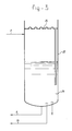
- Fig. 3 shows schematically the bottom end 22 of a distillation column for petroleum.
- the viscous residue 23 in the bottom of it can be conveyed for re-evaporation through pipe 6 to a re-evaporator which is in principle of the same design as the heat exchanger of Fig. 1.
- the discharge line 9 of this re-evaporator leads back to the top of the space 22 below the bottom bubble plate 24.
- the re-evaporator can operate with natural circulation.
- the medium used to feed in to the re-evaporator the solid particles for cleaning it can here be derived from the bottom of the distillation column through pipe 25, so that the pipe 17 of Fig. 1 is not necessary. Thus no cyclone 19 or similar separator in the top of the re-evaporator is necessary either. Any solid particles carried along out of the top of the re-evaporator pass through pipe 9 into the distillation column, which if the material of the solid particles is selected well is no problem because they can collect in the bottom of said column and can flow back again to the re-evaporator through pipe 6.
- the natural circulation means that no pump is needed in pipe 6.
- Pipe 25, which leads to pump 18 (Fig. 1) does, however, have to be placed and shielded in such a way that the solid particles cannot enter into it.
- Fig. 4 shows an evaporator which is equipped according to the invention. Apart from the same parts as those shown in Fig. 1, it has a central downpipe 26 and a cap 28 above it, so that a vapour/liquid separation which is known in principle is obtained in the top collection space 8, in which solid particles carried up are also sufficiently retained and will not be able to leave the evaporator through the outlet 9 with the vapour.
- the liquid feed through pipe 6 can take place above a protective edge 29, below which a pipe 30 can drain off, in order to convey a part of the liquid to pump 18 and from there to collector 13, from where it carries along the solid particles coming out of pipe 12 to pipe 14 and distributor 15 etc., as in the case of Fig. 1. So here again there is a star-shaped element 10 for forming sectors 11 to which the pipes 16 connect.
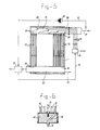
- Fig. 5 shows a plate heat exchanger of a type which is known per se.
- a heat exchanger has essentially vertical plates along which one medium flows at one side and the other medium at the other side, between which media heat exchange has to take place.
- the plates and the housing are in this case essentially rectangular with rounded edges and near each corner there is a common feed or discharge pipe for one or the other medium.
- One medium in this case flows from a common feed pipe into a left corner at the top or bottom to a common discharge pipe in a right corner at the bottom or top, and the other medium then flows from a common feed pipe, for example in the other left corner, to a common discharge pipe in the other right corner, but it can also flow from right to left.
- a countercurrent is thus produced, in which each flow is a combination of a transverse flow and a vertical flow, and in which one flow can run in the transverse direction and/or in the vertical direction in the same direction as or in counterflow to the other flow.
- Fig. 5 shows such a heat exchanger, in which the walls of the plates to be cleaned are in contact with the medium going down. If the invention is applied here to a rising flow, then it becomes more difficult to remove the descending solid cleaning particles from the bottom distribution space, which can then be carried out by, for example, draining off a part of the medium at 31 from the bottom collection space 32 during the cleaning and conveying that stream to collector 13.
- Fig. 5 the vertical section is staggered, in other words, it is shown for the same medium through the feed and discharge space (distribution or collection space), although they do not normally lie directly above one another, but one is at the top left and the other is at the bottom right in the heat exchanger.
- They can be spray heads with openings large enough to allow through the solid particles, and with a flow pattern so that there is no risk of blockage, thus for example with a delivery nozzle with a single opening, slightly larger than the feed pipe 16 itself.
- the solid particles are distributed in the medium flow in distribution space 34 by being carried along by it, in such a way that they reach a number of openings 35 very regularly distributed.
- a different group of openings 35 can in each case be provided with said solid particles by switching the distributor 15 over.
- the same system can be used for the other walls of the plates, through allowing solid particles into the distribution space on top for the other medium.
- the invention can be used in widely differing cases of heat exchange and types of heat exchangers, with forced circulation or thermosiphon flow, with falling or rising flows, and with cleaning of one or both walls of tubes or plates between the heat-exchanging media.
- the solid particles with a little medium in the sector 11 into which they are fed will fully or partially suppress boiling in the corresponding tubes 4, but that is no problem for the continued normal operation of the heat exchanger during cleaning, since in the other sectors boiling continues normally.
- particles with dimensions of 1 to 5 mm.
- chopped metal wire with a diameter of approx. 5 mm and a particle length of approx. 5 mm can, for example, be used.
- Hard, non-elastic particles are strongly preferred.
- gas it is preferable to use smaller particles.
- glass balls for example, having a diameter of 1 to 2 mm can often be considered.
- each particle should be smaller than the distance between the opposite walls of the spaces to be cleaned, so, in the case of circular tubes, smaller than the inner diameter thereof, which makes the particles freely movable therethrough without interrupting the heat exchange in the spaces, in which they are present for cleaning.
- Tubes 4 which are approximately 50 mm in diameter can be fed with solid particles in a quantity of up to several hundred kg per hour, both in the case of chopped wire and in the case of glass or other ceramic balls.
- the collector 13 for the solid particles coming out of the bottom of the heat exchanger can interact or be combined with a storage tank for the particles and with a separator for impurities carried along out of the heat exchanger.
- the impurities will generally leave the heat exchanger with the main flow of medium, and in the case of upward flow thereof will not go along with the solid cleaning particles.
- the collector 13 can also have an inlet for feeding in (new) solid particles and an outlet for discharging the solid particles from the system, for example for cleaning or replacement.
- a possible design of the collector 13 is one in which a rotating lock at the side of pipe 12 prevents short-circuiting. The pressure of pump or fan 18 is then fully utilized in the transportation of the particles from collector 13 to distributor 15.
- the collector 13 can be a tank in which the solid particles collect at the bottom, and in which the medium coming in from pipe 17 of pump or fan 18 flows downwards to an immersion pipe opening into the bottom of said tank and then upwards through said pipe to pipe 14 carrying solid particles with it.
- the distributor 15 can comprise a linearly moving slide with a single passage, locking means for locking the slide with said passage in position with each one of the pipes 16 as desired and a movement device for said slide which can be moved manually or with, for example, a linear motor.
- the distributor 15 can also be, and preferably is, a rotary slide with rotary drive means, with the connections to the pipes 16 not being disposed in line with each other, but in a circle.
- Many embodiments of this type of distributor are known. For example, such a distributor as shown in Fig.
- An inlet for solid particles can be fitted at any desired point in the system, for example in collector 13, in order to begin the process and to replenish the quantity of solid particles, while a drain for said particles can also be provided at said collector 13 or elsewhere.
- the drain-off flow of medium for circulation of the solid particles can be drained off from the infeed or from the discharge of the main stream, depending on the circumstances.
Landscapes
- Engineering & Computer Science (AREA)
- Chemical & Material Sciences (AREA)
- Combustion & Propulsion (AREA)
- Mechanical Engineering (AREA)
- General Engineering & Computer Science (AREA)
- Heat-Exchange Devices With Radiators And Conduit Assemblies (AREA)
- Manufacture Of Macromolecular Shaped Articles (AREA)
- Medicines That Contain Protein Lipid Enzymes And Other Medicines (AREA)
Applications Claiming Priority (2)
| Application Number | Priority Date | Filing Date | Title |
|---|---|---|---|
| NL9000919 | 1990-04-18 | ||
| NL9000919A NL9000919A (nl) | 1990-04-18 | 1990-04-18 | Werkwijze voor het reinigen van de wanden van warmtewisselaars en warmtewisselaar met middelen voor deze reiniging. |
Publications (2)
| Publication Number | Publication Date |
|---|---|
| EP0453043A1 true EP0453043A1 (fr) | 1991-10-23 |
| EP0453043B1 EP0453043B1 (fr) | 1995-01-11 |
Family
ID=19856955
Family Applications (1)
| Application Number | Title | Priority Date | Filing Date |
|---|---|---|---|
| EP91200909A Expired - Lifetime EP0453043B1 (fr) | 1990-04-18 | 1991-04-16 | Procédé pour nettoyer les parois d'un échangeur de chaleur et échangeur de chaleur comportant des moyens pour un tel nettoyage |
Country Status (10)
| Country | Link |
|---|---|
| US (1) | US5137081A (fr) |
| EP (1) | EP0453043B1 (fr) |
| JP (1) | JPH04227486A (fr) |
| AT (1) | ATE117071T1 (fr) |
| CA (1) | CA2040450A1 (fr) |
| DE (1) | DE69106565T2 (fr) |
| DK (1) | DK0453043T3 (fr) |
| ES (1) | ES2067137T3 (fr) |
| FI (1) | FI96065C (fr) |
| NL (1) | NL9000919A (fr) |
Cited By (6)
| Publication number | Priority date | Publication date | Assignee | Title |
|---|---|---|---|---|
| WO2000004333A1 (fr) | 1998-07-16 | 2000-01-27 | Hrs Spiratube S.L. | Ameliorations d'echangeurs de chaleur |
| RU2217376C2 (ru) * | 2002-02-08 | 2003-11-27 | Открытое акционерное общество "Сибирско-Уральская алюминиевая компания" | Способ очистки теплообменного аппарата от осадка бокситовой пульпы |
| RU2217375C2 (ru) * | 2002-01-11 | 2003-11-27 | Открытое акционерное общество "Сибирско-Уральская алюминиевая компания" | Способ выщелачивания боксита |
| FR2863697A1 (fr) * | 2003-12-12 | 2005-06-17 | Technos Et Cie | Echangeur de chaleur muni de moyens de nettoyage. |
| WO2007006293A1 (fr) * | 2005-07-12 | 2007-01-18 | Bruendermann Georg | Procede de nettoyage de chaudieres de centrale electrique |
| WO2010095110A3 (fr) * | 2009-02-23 | 2010-12-02 | Tube Tech International Ltd. | Echangeur de chaleur autonettoyant |
Families Citing this family (8)
| Publication number | Priority date | Publication date | Assignee | Title |
|---|---|---|---|---|
| US5512140A (en) * | 1994-01-11 | 1996-04-30 | Occidental Chemical Corporation | In-service cleaning of columns |
| FR2716530B1 (fr) * | 1994-02-24 | 1996-07-12 | Beaudrey & Cie | Dispositif d'interception pour éléments solides circulant dans un échangeur de chaleur pour le nettoyage de celui-ci. |
| DE19629641A1 (de) * | 1996-07-23 | 1998-01-29 | Metallgesellschaft Ag | Verfahren zum Entfernen von Verkrustungen in Eindampfanlagen |
| US6604577B2 (en) * | 2000-12-05 | 2003-08-12 | Eric P. Mulder | Geothermal heat pump cleaning control system and method |
| CN101010557B (zh) * | 2004-07-29 | 2011-06-08 | 缠绕机公司 | 具有用来再循环清洁颗粒的装置的换热器容器 |
| ITPD20120300A1 (it) | 2012-10-16 | 2014-04-17 | Fare S R L | Procedimento di pulizia di forni fusori a bacino per la produzione di articoli in vetro |
| GB2544288B (en) * | 2015-11-10 | 2018-05-02 | Ide Technologies Ltd | Cleaning a multi-effect evaporator |
| US10502510B2 (en) * | 2016-02-09 | 2019-12-10 | Babcock Power Services, Inc. | Cleaning tubesheets of heat exchangers |
Citations (2)
| Publication number | Priority date | Publication date | Assignee | Title |
|---|---|---|---|---|
| US2801824A (en) * | 1953-02-02 | 1957-08-06 | Taprogge Josef | Self-cleaning heat exchanger |
| DE2818006B1 (de) * | 1978-04-25 | 1979-08-09 | Taprogge Reinigungsanlagen | Roehrenwaermetauscher mit einer Reinigungseinrichtung |
Family Cites Families (7)
| Publication number | Priority date | Publication date | Assignee | Title |
|---|---|---|---|---|
| GB1509204A (en) * | 1974-11-14 | 1978-05-04 | Leslie Co | Self-cleaning heat exchanger circuit |
| US4237962A (en) * | 1978-08-11 | 1980-12-09 | Vandenhoeck J Paul | Self-cleaning heat exchanger |
| JPS5714193A (en) * | 1980-06-30 | 1982-01-25 | Hitachi Ltd | Distributing and controlling method of cleaning balls |
| US4366855A (en) * | 1981-02-27 | 1983-01-04 | Milpat Corporation | Self-cleaning recuperator |
| CA1216572A (fr) * | 1982-11-26 | 1987-01-13 | Hubertus W.A.A. Dries | Methode et dispositif de decrassage continu d'un echangeur de chaleur en cours d'exploitation |
| US4562885A (en) * | 1983-08-29 | 1986-01-07 | General Resource Corporation | Plate heat exchanger and pressure blast cleaner |
| US4569097A (en) * | 1983-11-23 | 1986-02-11 | Superior I.D. Tube Cleaners Incorporated | Tube cleaners |
-
1990
- 1990-04-18 NL NL9000919A patent/NL9000919A/nl not_active Application Discontinuation
-
1991
- 1991-04-15 CA CA002040450A patent/CA2040450A1/fr not_active Abandoned
- 1991-04-16 ES ES91200909T patent/ES2067137T3/es not_active Expired - Lifetime
- 1991-04-16 AT AT91200909T patent/ATE117071T1/de not_active IP Right Cessation
- 1991-04-16 EP EP91200909A patent/EP0453043B1/fr not_active Expired - Lifetime
- 1991-04-16 DE DE69106565T patent/DE69106565T2/de not_active Expired - Fee Related
- 1991-04-16 DK DK91200909.9T patent/DK0453043T3/da active
- 1991-04-17 US US07/686,826 patent/US5137081A/en not_active Expired - Fee Related
- 1991-04-17 FI FI911864A patent/FI96065C/fi not_active IP Right Cessation
- 1991-04-18 JP JP3112137A patent/JPH04227486A/ja active Pending
Patent Citations (2)
| Publication number | Priority date | Publication date | Assignee | Title |
|---|---|---|---|---|
| US2801824A (en) * | 1953-02-02 | 1957-08-06 | Taprogge Josef | Self-cleaning heat exchanger |
| DE2818006B1 (de) * | 1978-04-25 | 1979-08-09 | Taprogge Reinigungsanlagen | Roehrenwaermetauscher mit einer Reinigungseinrichtung |
Cited By (8)
| Publication number | Priority date | Publication date | Assignee | Title |
|---|---|---|---|---|
| WO2000004333A1 (fr) | 1998-07-16 | 2000-01-27 | Hrs Spiratube S.L. | Ameliorations d'echangeurs de chaleur |
| US6408936B2 (en) | 1998-07-16 | 2002-06-25 | Hrs Spiratube S.L. | To heat exchangers |
| RU2217375C2 (ru) * | 2002-01-11 | 2003-11-27 | Открытое акционерное общество "Сибирско-Уральская алюминиевая компания" | Способ выщелачивания боксита |
| RU2217376C2 (ru) * | 2002-02-08 | 2003-11-27 | Открытое акционерное общество "Сибирско-Уральская алюминиевая компания" | Способ очистки теплообменного аппарата от осадка бокситовой пульпы |
| FR2863697A1 (fr) * | 2003-12-12 | 2005-06-17 | Technos Et Cie | Echangeur de chaleur muni de moyens de nettoyage. |
| WO2005066573A1 (fr) * | 2003-12-12 | 2005-07-21 | Technos Et Compagnie | Echangeur de chaleur muni de moyens de nettoyage |
| WO2007006293A1 (fr) * | 2005-07-12 | 2007-01-18 | Bruendermann Georg | Procede de nettoyage de chaudieres de centrale electrique |
| WO2010095110A3 (fr) * | 2009-02-23 | 2010-12-02 | Tube Tech International Ltd. | Echangeur de chaleur autonettoyant |
Also Published As
| Publication number | Publication date |
|---|---|
| DE69106565T2 (de) | 1995-05-11 |
| DE69106565D1 (de) | 1995-02-23 |
| FI96065B (fi) | 1996-01-15 |
| CA2040450A1 (fr) | 1991-10-19 |
| ATE117071T1 (de) | 1995-01-15 |
| FI911864A0 (fi) | 1991-04-17 |
| EP0453043B1 (fr) | 1995-01-11 |
| JPH04227486A (ja) | 1992-08-17 |
| US5137081A (en) | 1992-08-11 |
| FI911864A7 (fi) | 1991-10-19 |
| NL9000919A (nl) | 1991-11-18 |
| FI96065C (fi) | 1996-04-25 |
| ES2067137T3 (es) | 1995-03-16 |
| DK0453043T3 (da) | 1995-03-20 |
Similar Documents
| Publication | Publication Date | Title |
|---|---|---|
| US5137081A (en) | Method for cleaning the walls of heat exchangers, and heat exchanger with means for said cleaning | |
| EP1580511B1 (fr) | Dispositif pour maintenir la température de matière en vrac | |
| EP2232167A1 (fr) | Échangeur thermique | |
| EP2921458B1 (fr) | Dispositif de séparation de solides d'eaux usées | |
| CN107281881A (zh) | 一种尾气处理装置及方法 | |
| US5575889A (en) | Rotating falling film evaporator | |
| EP0063834A1 (fr) | Echangeur de chaleur pour l'échange de chaleur entre liquides | |
| EP2896921B1 (fr) | Collecteur d'effluent d'échangeur de chaleur | |
| CN201567276U (zh) | 船用油污水分离处理装置 | |
| CN212282936U (zh) | 一种超重力旋转床及溶剂精馏系统 | |
| JPH0262290B2 (fr) | ||
| CN114712927A (zh) | 一种海水淡化系统换热器反洗过滤装置及其反洗方法 | |
| CN1822899A (zh) | 热交换器及具有这样的热交换器的反应器 | |
| CN113018959A (zh) | 一种低温多效海水淡化系统自动反洗过滤装置及其反洗方法 | |
| CN115773673B (zh) | 换热器、换热系统以及换热器的换热管的除垢方法 | |
| CN107137951B (zh) | 一种连续凝华结晶机 | |
| US4413673A (en) | Devices for supplying tube exchangers with cleaning bodies and for recovering these bodies | |
| SU1567117A3 (ru) | Сгуститель | |
| CN115138136A (zh) | 一种共沉淀反应系统及其过滤浓缩装置 | |
| EP0212011B1 (fr) | Evaporateur à multiples étages | |
| SU1699548A1 (ru) | Установка дл улавливани летучих веществ из газовых выбросов | |
| RU2819141C2 (ru) | Способ и кристаллизационный резервуар и соответствующее устройство для кристаллизации нитрата кальция из нитрофосфатного процесса | |
| WO1996007467A9 (fr) | Procede et appareil pour eliminer des contaminants organiques | |
| CN119280897B (zh) | 一种螺带式斜管沉降模块和螺带式斜管分区沉降模块 | |
| CN120020482A (zh) | 热交换器模块及其方法 |
Legal Events
| Date | Code | Title | Description |
|---|---|---|---|
| PUAI | Public reference made under article 153(3) epc to a published international application that has entered the european phase |
Free format text: ORIGINAL CODE: 0009012 |
|
| AK | Designated contracting states |
Kind code of ref document: A1 Designated state(s): AT BE CH DE DK ES FR GB IT LI NL SE |
|
| 17P | Request for examination filed |
Effective date: 19920617 |
|
| 17Q | First examination report despatched |
Effective date: 19921030 |
|
| GRAA | (expected) grant |
Free format text: ORIGINAL CODE: 0009210 |
|
| AK | Designated contracting states |
Kind code of ref document: B1 Designated state(s): AT BE CH DE DK ES FR GB IT LI NL SE |
|
| REF | Corresponds to: |
Ref document number: 117071 Country of ref document: AT Date of ref document: 19950115 Kind code of ref document: T |
|
| ITF | It: translation for a ep patent filed | ||
| EAL | Se: european patent in force in sweden |
Ref document number: 91200909.9 |
|
| REF | Corresponds to: |
Ref document number: 69106565 Country of ref document: DE Date of ref document: 19950223 |
|
| REG | Reference to a national code |
Ref country code: ES Ref legal event code: FG2A Ref document number: 2067137 Country of ref document: ES Kind code of ref document: T3 |
|
| REG | Reference to a national code |
Ref country code: DK Ref legal event code: T3 |
|
| ET | Fr: translation filed | ||
| PLBE | No opposition filed within time limit |
Free format text: ORIGINAL CODE: 0009261 |
|
| STAA | Information on the status of an ep patent application or granted ep patent |
Free format text: STATUS: NO OPPOSITION FILED WITHIN TIME LIMIT |
|
| 26N | No opposition filed | ||
| PGFP | Annual fee paid to national office [announced via postgrant information from national office to epo] |
Ref country code: SE Payment date: 19970326 Year of fee payment: 7 |
|
| PGFP | Annual fee paid to national office [announced via postgrant information from national office to epo] |
Ref country code: FR Payment date: 19970328 Year of fee payment: 7 |
|
| PGFP | Annual fee paid to national office [announced via postgrant information from national office to epo] |
Ref country code: AT Payment date: 19970407 Year of fee payment: 7 |
|
| PGFP | Annual fee paid to national office [announced via postgrant information from national office to epo] |
Ref country code: GB Payment date: 19970409 Year of fee payment: 7 |
|
| PGFP | Annual fee paid to national office [announced via postgrant information from national office to epo] |
Ref country code: CH Payment date: 19970411 Year of fee payment: 7 |
|
| PGFP | Annual fee paid to national office [announced via postgrant information from national office to epo] |
Ref country code: ES Payment date: 19970415 Year of fee payment: 7 |
|
| PGFP | Annual fee paid to national office [announced via postgrant information from national office to epo] |
Ref country code: BE Payment date: 19970416 Year of fee payment: 7 |
|
| PGFP | Annual fee paid to national office [announced via postgrant information from national office to epo] |
Ref country code: DK Payment date: 19970418 Year of fee payment: 7 |
|
| PGFP | Annual fee paid to national office [announced via postgrant information from national office to epo] |
Ref country code: NL Payment date: 19970430 Year of fee payment: 7 Ref country code: DE Payment date: 19970430 Year of fee payment: 7 |
|
| PG25 | Lapsed in a contracting state [announced via postgrant information from national office to epo] |
Ref country code: GB Free format text: LAPSE BECAUSE OF NON-PAYMENT OF DUE FEES Effective date: 19980416 Ref country code: AT Free format text: LAPSE BECAUSE OF NON-PAYMENT OF DUE FEES Effective date: 19980416 |
|
| PG25 | Lapsed in a contracting state [announced via postgrant information from national office to epo] |
Ref country code: SE Free format text: LAPSE BECAUSE OF NON-PAYMENT OF DUE FEES Effective date: 19980417 Ref country code: ES Free format text: LAPSE BECAUSE OF NON-PAYMENT OF DUE FEES Effective date: 19980417 |
|
| PG25 | Lapsed in a contracting state [announced via postgrant information from national office to epo] |
Ref country code: LI Free format text: LAPSE BECAUSE OF NON-PAYMENT OF DUE FEES Effective date: 19980430 Ref country code: FR Free format text: THE PATENT HAS BEEN ANNULLED BY A DECISION OF A NATIONAL AUTHORITY Effective date: 19980430 Ref country code: DK Free format text: LAPSE BECAUSE OF NON-PAYMENT OF DUE FEES Effective date: 19980430 Ref country code: CH Free format text: LAPSE BECAUSE OF NON-PAYMENT OF DUE FEES Effective date: 19980430 Ref country code: BE Free format text: LAPSE BECAUSE OF NON-PAYMENT OF DUE FEES Effective date: 19980430 |
|
| BERE | Be: lapsed |
Owner name: ESKLA B.V. Effective date: 19980430 |
|
| PG25 | Lapsed in a contracting state [announced via postgrant information from national office to epo] |
Ref country code: NL Free format text: LAPSE BECAUSE OF NON-PAYMENT OF DUE FEES Effective date: 19981101 |
|
| GBPC | Gb: european patent ceased through non-payment of renewal fee |
Effective date: 19980416 |
|
| REG | Reference to a national code |
Ref country code: CH Ref legal event code: PL |
|
| NLV4 | Nl: lapsed or anulled due to non-payment of the annual fee |
Effective date: 19981101 |
|
| EUG | Se: european patent has lapsed |
Ref document number: 91200909.9 |
|
| PG25 | Lapsed in a contracting state [announced via postgrant information from national office to epo] |
Ref country code: DE Free format text: LAPSE BECAUSE OF NON-PAYMENT OF DUE FEES Effective date: 19990202 |
|
| REG | Reference to a national code |
Ref country code: FR Ref legal event code: ST |
|
| REG | Reference to a national code |
Ref country code: DK Ref legal event code: EBP |
|
| REG | Reference to a national code |
Ref country code: ES Ref legal event code: FD2A Effective date: 20000503 |
|
| PG25 | Lapsed in a contracting state [announced via postgrant information from national office to epo] |
Ref country code: IT Free format text: LAPSE BECAUSE OF NON-PAYMENT OF DUE FEES;WARNING: LAPSES OF ITALIAN PATENTS WITH EFFECTIVE DATE BEFORE 2007 MAY HAVE OCCURRED AT ANY TIME BEFORE 2007. THE CORRECT EFFECTIVE DATE MAY BE DIFFERENT FROM THE ONE RECORDED. Effective date: 20050416 |