EP0453092B1 - Eclairage uniforme de surfaces étendues et minces, adapté en particulier aux automobiles - Google Patents
Eclairage uniforme de surfaces étendues et minces, adapté en particulier aux automobiles Download PDFInfo
- Publication number
- EP0453092B1 EP0453092B1 EP91302247A EP91302247A EP0453092B1 EP 0453092 B1 EP0453092 B1 EP 0453092B1 EP 91302247 A EP91302247 A EP 91302247A EP 91302247 A EP91302247 A EP 91302247A EP 0453092 B1 EP0453092 B1 EP 0453092B1
- Authority
- EP
- European Patent Office
- Prior art keywords
- wedge
- light
- illuminator
- recited
- edge
- Prior art date
- Legal status (The legal status is an assumption and is not a legal conclusion. Google has not performed a legal analysis and makes no representation as to the accuracy of the status listed.)
- Expired - Lifetime
Links
Images


Classifications
-
- G—PHYSICS
- G02—OPTICS
- G02B—OPTICAL ELEMENTS, SYSTEMS OR APPARATUS
- G02B6/00—Light guides; Structural details of arrangements comprising light guides and other optical elements, e.g. couplings
- G02B6/0001—Light guides; Structural details of arrangements comprising light guides and other optical elements, e.g. couplings specially adapted for lighting devices or systems
- G02B6/0011—Light guides; Structural details of arrangements comprising light guides and other optical elements, e.g. couplings specially adapted for lighting devices or systems the light guides being planar or of plate-like form
- G02B6/0013—Means for improving the coupling-in of light from the light source into the light guide
- G02B6/0023—Means for improving the coupling-in of light from the light source into the light guide provided by one optical element, or plurality thereof, placed between the light guide and the light source, or around the light source
- G02B6/0028—Light guide, e.g. taper
-
- F—MECHANICAL ENGINEERING; LIGHTING; HEATING; WEAPONS; BLASTING
- F21—LIGHTING
- F21S—NON-PORTABLE LIGHTING DEVICES; SYSTEMS THEREOF; VEHICLE LIGHTING DEVICES SPECIALLY ADAPTED FOR VEHICLE EXTERIORS
- F21S43/00—Signalling devices specially adapted for vehicle exteriors, e.g. brake lamps, direction indicator lights or reversing lights
- F21S43/20—Signalling devices specially adapted for vehicle exteriors, e.g. brake lamps, direction indicator lights or reversing lights characterised by refractors, transparent cover plates, light guides or filters
- F21S43/235—Light guides
- F21S43/236—Light guides characterised by the shape of the light guide
- F21S43/239—Light guides characterised by the shape of the light guide plate-shaped
-
- F—MECHANICAL ENGINEERING; LIGHTING; HEATING; WEAPONS; BLASTING
- F21—LIGHTING
- F21S—NON-PORTABLE LIGHTING DEVICES; SYSTEMS THEREOF; VEHICLE LIGHTING DEVICES SPECIALLY ADAPTED FOR VEHICLE EXTERIORS
- F21S43/00—Signalling devices specially adapted for vehicle exteriors, e.g. brake lamps, direction indicator lights or reversing lights
- F21S43/20—Signalling devices specially adapted for vehicle exteriors, e.g. brake lamps, direction indicator lights or reversing lights characterised by refractors, transparent cover plates, light guides or filters
- F21S43/235—Light guides
- F21S43/242—Light guides characterised by the emission area
- F21S43/245—Light guides characterised by the emission area emitting light from one or more of its major surfaces
-
- F—MECHANICAL ENGINEERING; LIGHTING; HEATING; WEAPONS; BLASTING
- F21—LIGHTING
- F21S—NON-PORTABLE LIGHTING DEVICES; SYSTEMS THEREOF; VEHICLE LIGHTING DEVICES SPECIALLY ADAPTED FOR VEHICLE EXTERIORS
- F21S43/00—Signalling devices specially adapted for vehicle exteriors, e.g. brake lamps, direction indicator lights or reversing lights
- F21S43/20—Signalling devices specially adapted for vehicle exteriors, e.g. brake lamps, direction indicator lights or reversing lights characterised by refractors, transparent cover plates, light guides or filters
- F21S43/235—Light guides
- F21S43/247—Light guides with a single light source being coupled into the light guide
-
- F—MECHANICAL ENGINEERING; LIGHTING; HEATING; WEAPONS; BLASTING
- F21—LIGHTING
- F21S—NON-PORTABLE LIGHTING DEVICES; SYSTEMS THEREOF; VEHICLE LIGHTING DEVICES SPECIALLY ADAPTED FOR VEHICLE EXTERIORS
- F21S43/00—Signalling devices specially adapted for vehicle exteriors, e.g. brake lamps, direction indicator lights or reversing lights
- F21S43/20—Signalling devices specially adapted for vehicle exteriors, e.g. brake lamps, direction indicator lights or reversing lights characterised by refractors, transparent cover plates, light guides or filters
- F21S43/235—Light guides
- F21S43/249—Light guides with two or more light sources being coupled into the light guide
-
- F—MECHANICAL ENGINEERING; LIGHTING; HEATING; WEAPONS; BLASTING
- F21—LIGHTING
- F21S—NON-PORTABLE LIGHTING DEVICES; SYSTEMS THEREOF; VEHICLE LIGHTING DEVICES SPECIALLY ADAPTED FOR VEHICLE EXTERIORS
- F21S43/00—Signalling devices specially adapted for vehicle exteriors, e.g. brake lamps, direction indicator lights or reversing lights
- F21S43/20—Signalling devices specially adapted for vehicle exteriors, e.g. brake lamps, direction indicator lights or reversing lights characterised by refractors, transparent cover plates, light guides or filters
- F21S43/235—Light guides
- F21S43/251—Light guides the light guides being used to transmit light from remote light sources
-
- F—MECHANICAL ENGINEERING; LIGHTING; HEATING; WEAPONS; BLASTING
- F21—LIGHTING
- F21S—NON-PORTABLE LIGHTING DEVICES; SYSTEMS THEREOF; VEHICLE LIGHTING DEVICES SPECIALLY ADAPTED FOR VEHICLE EXTERIORS
- F21S43/00—Signalling devices specially adapted for vehicle exteriors, e.g. brake lamps, direction indicator lights or reversing lights
- F21S43/20—Signalling devices specially adapted for vehicle exteriors, e.g. brake lamps, direction indicator lights or reversing lights characterised by refractors, transparent cover plates, light guides or filters
- F21S43/281—Materials thereof; Structures thereof; Properties thereof; Coatings thereof
- F21S43/2811—Heterogeneous materials
-
- G—PHYSICS
- G02—OPTICS
- G02B—OPTICAL ELEMENTS, SYSTEMS OR APPARATUS
- G02B6/00—Light guides; Structural details of arrangements comprising light guides and other optical elements, e.g. couplings
- G02B6/0001—Light guides; Structural details of arrangements comprising light guides and other optical elements, e.g. couplings specially adapted for lighting devices or systems
- G02B6/0005—Light guides; Structural details of arrangements comprising light guides and other optical elements, e.g. couplings specially adapted for lighting devices or systems the light guides being of the fibre type
- G02B6/0008—Light guides; Structural details of arrangements comprising light guides and other optical elements, e.g. couplings specially adapted for lighting devices or systems the light guides being of the fibre type the light being emitted at the end of the fibre
-
- G—PHYSICS
- G02—OPTICS
- G02B—OPTICAL ELEMENTS, SYSTEMS OR APPARATUS
- G02B6/00—Light guides; Structural details of arrangements comprising light guides and other optical elements, e.g. couplings
- G02B6/0001—Light guides; Structural details of arrangements comprising light guides and other optical elements, e.g. couplings specially adapted for lighting devices or systems
- G02B6/0011—Light guides; Structural details of arrangements comprising light guides and other optical elements, e.g. couplings specially adapted for lighting devices or systems the light guides being planar or of plate-like form
- G02B6/0033—Means for improving the coupling-out of light from the light guide
- G02B6/0035—Means for improving the coupling-out of light from the light guide provided on the surface of the light guide or in the bulk of it
- G02B6/004—Scattering dots or dot-like elements, e.g. microbeads, scattering particles, nanoparticles
-
- G—PHYSICS
- G02—OPTICS
- G02B—OPTICAL ELEMENTS, SYSTEMS OR APPARATUS
- G02B6/00—Light guides; Structural details of arrangements comprising light guides and other optical elements, e.g. couplings
- G02B6/0001—Light guides; Structural details of arrangements comprising light guides and other optical elements, e.g. couplings specially adapted for lighting devices or systems
- G02B6/0011—Light guides; Structural details of arrangements comprising light guides and other optical elements, e.g. couplings specially adapted for lighting devices or systems the light guides being planar or of plate-like form
- G02B6/0033—Means for improving the coupling-out of light from the light guide
- G02B6/0035—Means for improving the coupling-out of light from the light guide provided on the surface of the light guide or in the bulk of it
- G02B6/0045—Means for improving the coupling-out of light from the light guide provided on the surface of the light guide or in the bulk of it by shaping at least a portion of the light guide
- G02B6/0046—Tapered light guide, e.g. wedge-shaped light guide
-
- G—PHYSICS
- G02—OPTICS
- G02B—OPTICAL ELEMENTS, SYSTEMS OR APPARATUS
- G02B6/00—Light guides; Structural details of arrangements comprising light guides and other optical elements, e.g. couplings
- G02B6/0001—Light guides; Structural details of arrangements comprising light guides and other optical elements, e.g. couplings specially adapted for lighting devices or systems
- G02B6/0011—Light guides; Structural details of arrangements comprising light guides and other optical elements, e.g. couplings specially adapted for lighting devices or systems the light guides being planar or of plate-like form
- G02B6/0065—Manufacturing aspects; Material aspects
Definitions
- the present invention generally relates to the illumination of large surfaces and, more particularly, to providing uniform illumination over large areas at a shallow depth which is particularly suited for automobiles.
- LCDs liquid crystal displays
- Current illuminators for LCDs use fluorescent lamps of high efficiency and light box cavities to provide uniform illumination.
- the LCDs are now generally provided with a source of back lighting. In order to retain the advantage of LCDs being used as a thin flat panel display, this back lighting source must also be thin. This type of design must be of a certain minimum thickness due to the lamp size and light box cavity size to achieve a uniform backlighting of the display.
- Lumitex, Inc Another type of illuminator which achieves uniform illumination over a large area and yet is thin is manufactured by Lumitex, Inc.
- the Lumitex device uses a high efficiency light source and collects and concentrates this light by focusing it into an optical fiber bundle.
- the fibers of the bundle are fanned out and woven into a flat panel. Light is made to leak from the woven panel by sharp bending of the fibers in the weave pattern.
- the disadvantages of this device are its cost of construction and the lack of directionality of the leaked light and efficiency when designed to achieve a high degree of uniformity.
- US-A-4 466 697 proposes an optical fibre which is doped in the core region with refractive and/or reflective light scattering particles so that the fibre emits light along its length.
- US-A-4 528 617 discloses an illuminator for large surface areas comprising: a transparent wedge having back and front surfaces and a generally rectangular shaped edge between said surfaces, said front surface being co-extensive with an area to be illuminated; a light source; and at least one light guide optically coupling light from said light source to said rectangular shaped edge so that light entering the wedge is internally reflected from the back surface and emitted from said front surface.
- two such wedges are adjoined along a common edge.
- an illuminator for large surface areas comprising: a transparent wedge having back and front surfaces and a generally rectangular shaped edge between said surfaces, said front surface being co-extensive with an area to be illuminated; a high efficiency light source; at least one light guide optically coupling light from said light source to said rectangular shaped edge so that light entering the wedge is internally reflected from the back surface and emitted from said front surface; characterized by said wedge being provided with scattering centers throughout its volume and said scattering centers being encapsulated liquid crystals and further comprising means for applying an electric field across said front and back surfaces of said wedge.
- an illuminator for large surface areas comprising: a transparent wedge having back and front surfaces and a generally rectangularly shaped edge between said surfaces, said front surface being co-extensive with an area to be illuminated; a high efficiency light source; at least one light guide optically coupling light from said light source to said rectangular shaped edge so that light entering the wedge is internally reflected from the back surface and emitted from said front surface, characterized by said transparent wedge being provided with scattering centers in its volume, and the number of scattering centers increasing along a distance moving away from said rectangular shaped edge.
- an illuminator for large surface areas comprising: at least first and second transparent wedges each having back and front surfaces and a generally rectangular shaped edge between said surfaces, said front surface being co-extensive with an area to be illuminated; said wedges being joined along a common edge; a high efficiency light source; at least one light guide optically coupling light from said light source to at least one of said rectangular shaped edges so that light entering at least one of the wedges is internally reflected from the back surface and emitted from said front surface; and characterized by each of said transparent wedges being provided with scattering centers throughout its volume, the number of scattering centers increasing toward the said common edge.
- the illuminating device includes a transparent plastic wedge 12.
- the wedge may be made of a moldable thermoplastic such as, for example, acrylics, polycarbonates or polystyrenes.
- a high efficiency source 16 which may be, for example, an arc lamp centrally located in a reflector preferably having a spherical shape.
- the coupling between the ends of the fibers 14 and the wedge 12 may be made by melting them together or mated in some other way so as to reduce any reflection losses and which provides for the light from the fibers to spread out in a direction perpendicular to the direction of the beam so as to provide uniform illumination over the front or light emitting surface 18.
- the front surface 18 is arranged to be co-extensive with the area to be illuminated.
- the back surface 20, shown in more detail in Figure 2, of the wedge is coated with a reflecting coating.
- this reflecting coating is a diffuse reflector such as Barium Sulfate, BaS04, as manufactured by Kodak of Rochester, New York, for this purpose.
- the reflecting coating may be a specular reflector, such as sputtered aluminum, but this generally does not produce as good a result as a diffuse reflector.
- Figure 2 illustrates the reflections of light from one of the optical fibers 14 located at the rectangular edge 13 within the volume of the wedge 12.
- Figure 2 illustrates the back surface 20 in a different manner than it was shown in Figure 1 in that back surface 20 now converges relative to the light emitting surface 18.
- the challenge in illuminating a large area represented by illuminating device 18 is to make the illumination fairly uniform.
- the wedge 12 increases the angle of the reflections per unit distance as the wedge gets thinner and the back or reflecting surface 20 intercepts more of the light beam, shown as rays 19a,...19n emitted from fiber 14 located at surface 13, as such a beam travels toward the apex of the wedge.
- the scattering effect increases in the direction away from the source 14.
- the reflector or reflective coating on the back surface 20 ensures that all of the light not absorbed by the reflector is reflected by the reflector and comes out through the front surface 18. Either principle by itself provides some improvement in uniformity so that in some applications, only one or the other might be used.
- the scattering sources may be formed on the front surface 18, by scratching or grooving or coating the surface 18, where the density of scattering sources is low near the source 14 of the light and increases as the distance from the source increases.
- the scattering sources are illustrated in Figures 3A and 3B which show, respectively, grooves 17A and pits 17B as scattering sources which preferably increase in frequency of occurrence or density over the surface as their location moves away from the source of illumination 14 located at rectangular edge 13.
- the scattering sources may be formed within the volume of the material, again with the guideline that the related density increases as the distance from the source increases.
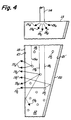
- Figure 4 which shows scattering particles 17c within the volume of the wedge 12.
- the scattered light rays are shown as groups 19a...19c which are composed of individual rays 19a...19n that are emitted from optical fiber 14 at rectangular edge 13.
- These particles may be passive or inert types mixed with the thermoplastic material and allowed to gradually settle toward the apex end of the wedge before curing the plastic thereby producing the increasing density of such light scattering centers as generally illustrated.
- the particles could be encapsulated liquid crystals such as those described in U.S. Patents No. 4,435,047 and No. 4,616,903 to Fergason and produced by Taliq Corp. of Sunnyvale, California.
- Transparent electrodes 21 and 21′ are applied over the front and back surfaces 18 and 20, respectively, of the wedge 12 for the purpose of applying an electric field.
- the application of an electric field has the effect of aligning the liquid crystals parallel to the direction of the field, in contrast to its normally structurally distorted shape in the absence of a field.
- the liquid crystals become more transparent, as their transparency is a function of the strength of the electric field. If the liquid crystals are nonuniformly distributed through the volume of the wedge, the application of a uniform electric field across the volume controls the light scattering effect desired.
- the use of encapsulated liquid crystals allows for some flexibility of manufacture.
- the encapsulated liquid crystals may be uniformly distributed within the volume of the wedge 12 and a nonuniform electric field applied across the wedge to produce the effect of an increasing density of light scattering centers.
- the electric field applied across the envelope the illuminating light emitted from the front surface 18 of the wedge 12 may be made more or less uniform as desired by the application.
- the applique When the illuminating device according to the invention is used to illuminate, for example, an applique (cutout decoration fastened to a larger piece of material) on the rear deck of a car, the applique may be formed by molding plastic such that the back surface forms a series of wedges relative to the front surface and such that each wedge may be illuminated by means of fiber optics at the thick end or edge of the wedge.
- the back surface is roughened and coated with the previously discussed diffuse reflector so that all of the light not absorbed by the back surface is reflected by the back surface and comes through the front surface 18 of the applique.
- the purpose of the wedge shape is to provide illumination through the front surface 18 which is as uniform as possible.
- the applique be reflective it may be made in two layers, the outer layer of which is provided with the usual corner cube reflective surface on the back, while the second layer has the wedge construction as generally shown in Figure 1.
- the source of light into the fibers may be a discharge lamp light source centrally located with the reflector or a similar high efficiency light source.
- a discharge lamp may be mounted on the deck lid without fear of high acceleration, since there is no filament to fail.
- the light beam introduced into the plastic wedge 12 is the nature of the light beam introduced into the plastic wedge 12. Generally, it is preferred that the light beam be collimated, or nearly so, to achieve the best uniformity of illuminating light emitted from the front surface 18 of the wedge. Secondly, the thickness and the angle of the wedge should be determined for the specific application. And finally, when used, a decision must be made on the location and distribution of light scattering centers, either over the emitting surface 18 or within the volume of the wedge 12.
- FIGS 5 and 6 A practical example of the invention is shown in Figures 5 and 6 which illustrate a double wedge illuminating device 22 fabricated to illuminate an automobile speedometer.
- the speedometer itself was fabricated using LCD technology, and the double wedge structure was used to backlight the LCD.
- light is collected and concentrated from a high efficiency light source (not shown) as before.
- the concentrated light is focused as an input to a pair of light guides 24 which transmit light, shown in Figure 5 as rays 25a...25n, into edges 28 and 30 of the double wedge 26.
- the edge 28 is comprised of portions 28A, 28B, 28C and 28D
- edge 30 is comprised of portions 30A, 30B, 30C and 30D.
- the double wedge shape is best seen in Figure 6 in which the two wedge portions 26 are joined at a common edge 33.
- the illuminator 22 having the back (32) and front (34) surfaces of each wedge 26 converge and the front surfaces 34 of the two wedges 26 forming a common illuminating surface conforming to a surface that is to be illuminated.
- the expanding beams of light 25a...25n are intercepted by serrated edge portions 28A...30D which reflect the light rays toward the thinner central part of the double wedge 26.
- the surfaces of the serrated edges 28 and 30 are coated with a specular reflector, such as sputtered aluminum.
- the serrations are designed such that the light beams 25a...25n are divided into seven parts of roughly equal lumens.
- the seven distributed light beams of the serrated edges 28 and 30 are reflected by the back surface 32 ( Figure 5) of the double wedge and are emitted from the front surface 34 ( Figure 6) in the same manner as the generalized structure shown in Figure 1.
- Figure 7 shows in more detail the back surface 32 of the double wedge 26 shown in Figure 6.
- the back surface may be grooved by means of grooves 17A, discussed with regards to Figure 3A, perpendicular to the direction from which the light (shown by rays 25a and 25n) is propagated from so am to form a surface that is stepped with 45° risers 36.
- the risers 36 intercept light rays 25a and 25n and redirect the light through the front surface 34 into groups of light rays 27.
- An alternative to grooving (17A) the back surface 32 is to texture the front surface 34 by simple rough sanding. The purpose of the sanding is to defeat total internal reflection and scatter the light striking this surface thereby allowing the light to escape.
- the entire plastic form of wedge 22 is coated with a diffuse reflective coating 38 to assure that any light which is not totally internally reflected is returned to the plastic cavity of wedge 22 and contributes to the output of wedge 22.
Landscapes
- Engineering & Computer Science (AREA)
- General Engineering & Computer Science (AREA)
- Physics & Mathematics (AREA)
- General Physics & Mathematics (AREA)
- Optics & Photonics (AREA)
- Planar Illumination Modules (AREA)
- Light Guides In General And Applications Therefor (AREA)
- Optical Elements Other Than Lenses (AREA)
- Lighting Device Outwards From Vehicle And Optical Signal (AREA)
- Non-Portable Lighting Devices Or Systems Thereof (AREA)
Claims (15)
- Dispositif d'éclairage pour des zones de surface étendue comprenant; :
un coin transparent (12) comportant des surfaces arrière (20) et avant (18) et un bord (13) de forme rectangulaire dans son ensemble entre lesdites surfaces, ladite surface avant ayant la même étendue qu'une zone à éclairer;
une source lumineuse (16) de haut rendement;
au moins un guide (14) de lumière couplant optiquement la lumière en provenance de ladite source lumineuse audit bord de forme rectangulaire, de telle sorte que la lumière entrant dans le coin soit réfléchie intérieurement par la surface arrière (20) et émise par ladite surface avant (18), caractérisé en ce que ledit coin est pourvu de centres de diffusion (17c) dans la totalité de son volume et lesdits centres de diffusion sont des cristaux liquides encapsulés et en ce qu'en outre il comprend des moyens (21, 21′) pour appliquer un champ électrique en travers desdites surfaces avant et arrière dudit coin. - Dispositif d'éclairage selon la revendication 1, dans lequel ledit coin (12) est en matière plastique.
- Dispositif d'éclairage selon la revendication 2, dans lequel ladite matière plastique est une matière thermoplastique et ledit guide (14) de lumière fusionne avec ledit coin (12) de manière à réduire toutes pertes par réflexion et amener la lumière en provenance dudit guide à se disperser à l'intérieur dudit coin en matière plastique;
- Dispositif d'éclairage selon les revendications 1, 2 ou 3, dans lequel ladite surface avant (18) fait partie intégrante de la zone superficielle à éclairer.
- Dispositif d'éclairage pour des zones de surface étendue, comprenant:
un coin transparent (12) comportant des surfaces arrière (20) et avant (18) et un bord (13) de forme rectangulaire dans son ensemble entre lesdites surfaces, ladite surface avant (18) ayant la même étendue que la zone à éclairer;
une source lumineuse (16) de haut rendement;
au moins un guide (14) de lumière couplant optiquement la lumire en provenance de ladite source lumineuse audit bord (13) de forme rectangulaire, de telle sorte que la lumière entrant dans le coin soit réfléchie intérieurement par la surface arrière et soit émise depuis la surface avant, caractérisé en ce que
ledit coin transparent est pourvu de centres de diffusion (17abc) dans son volume, et
le nombre de centres de diffusion augmente à mesure que l'on s'éloigne dudit bord (13) de forme rectangulaire. - Dispositif d'éclairage selon la revendication 5, dans lequel lesdits centres de diffusion sont des rainures (17a) formées dans ledit volume, perpendiculairement à la direction de propagation de la lumièreà l'intérieur dudit coin et présentant une fréquence d'occurence qui augmente à mesure que l'on s'éloigne dudit bord de forme rectangulaire.
- Dispositif d'éclairage selon la revendication 5, dans lequel lesdits centres de diffusion sont des microcuvettes (17b) formées dans ledit volume et présentant une densité qui augmente à mesure que l'on s'éloigne dudit bord de forme rectangulaire;
- Dispositif d'éclairage selon la revendication 5, dans lequel les centres de diffusion (17) sont présents dans tout le volume du coin (12).
- Dispositif d'éclairage selon la revendication 5, dans lequel ledit guide de lumière (24) au nombre d'au moins un est couplé audit coin au voisinage immédiat dudit bord rectangulaire et parallèlement à ce bord et ledit bord rectangulaire est strié (28a-d, 30a-d) pour réfléchir la lumière en provenance dudit guide de lumière en direction desdites surfaces arrière et avant;
- Dispositif d'éclairage selon la revendication 5, dans lequel ladite surface arrière est rainurée (17a) pour former des surfaces (36) perpendiculaires à la direction de la lumière (25) se propageant à l'intérieur dudit coin, grâce à quoi la lumière (27) est réfléchie par lesdites surfaces (36) en direction de ladite surface avant.
- Dispositif d'éclairage (22) pour des zones de surface étendue, comprenant :
au moins des premier et second coins transparents (26) comportant chacun des surfaces avant et arrière et un bord de forme rectangulaire dans son ensemble entre lesdites surfaces, la surface avant ayant la même étendue que la zone à éclairer,
lesdits coins étant réunis le long d'un bord commun;
une source lumineuse (16) de haut rendement;
au moins un guide de lumière (24) couplant optiquement la lumière en provenance de ladite source de lumière à au moins un desdits bords (28) de forme rectangulaire, de telle sorte que la lumière entrant dans au moins un des coins soit réfléchie intérieurement par la surface arrière et soit émise à partir de la surface avant; et caractérisé en ce que chacun desdits coins transparents est pourvu de centres de diffusion (17c) dans tout son volume, le nombre de centres de diffusion (17c) augmentant en direction du bord commun; - Dispositif d'éclairage selon la revendication 11, dans lequel le nombre de coins est d'au moins deux et lesdits coins sont réunis le long d'un bord commun où lesdites surfaces arrière et avant de chaque coin convergent et les surfaces avant desdits coins forment une surface d'éclairage commune épousant la forme de la zone de surface à éclairer;
- Dispositif d'éclairage selon la revendication 11, dans lequel au moins un guide de lumière (24) est prévu pour chacun desdits coins, et chaque guide de lumière est couplé à un coin correspondant en matière plastique de façon immédiatement adjacente et parallèle au bord rectangulaire de ce coin, et ledit bord rectangulaire est strié (28, 30) pour réfléchir la lumière en provenance dudit guide de lumière en direction desdites surfaces arrière et avant;
- Dispositif d'éclairage selon l'une quelconque des revendications 1 à 13, comprenant en outre un revêtement réflecteur (38) appliqué à ladites ou auxdites surfaces arrière convergentes
- Dispositif d'éclairage selon la revendication 14, dans lequel ledit revêtement réflecteur (38) est du typeà diffusion.
Applications Claiming Priority (2)
| Application Number | Priority Date | Filing Date | Title |
|---|---|---|---|
| US07/496,485 US5101325A (en) | 1990-03-20 | 1990-03-20 | Uniform illumination of large, thin surfaces particularly suited for automotive applications |
| US496485 | 1990-03-20 |
Publications (2)
| Publication Number | Publication Date |
|---|---|
| EP0453092A1 EP0453092A1 (fr) | 1991-10-23 |
| EP0453092B1 true EP0453092B1 (fr) | 1994-08-17 |
Family
ID=23972848
Family Applications (1)
| Application Number | Title | Priority Date | Filing Date |
|---|---|---|---|
| EP91302247A Expired - Lifetime EP0453092B1 (fr) | 1990-03-20 | 1991-03-15 | Eclairage uniforme de surfaces étendues et minces, adapté en particulier aux automobiles |
Country Status (5)
| Country | Link |
|---|---|
| US (1) | US5101325A (fr) |
| EP (1) | EP0453092B1 (fr) |
| JP (1) | JPH07120485B2 (fr) |
| CA (1) | CA2034378C (fr) |
| DE (1) | DE69103456T2 (fr) |
Cited By (7)
| Publication number | Priority date | Publication date | Assignee | Title |
|---|---|---|---|---|
| US7357548B2 (en) | 2003-09-08 | 2008-04-15 | Koninklijke Philips Electronics, N.V. | Light-guiding system comprising a number of light transmission rods |
| CN103153702A (zh) * | 2010-07-30 | 2013-06-12 | 汽车照明后灯法国有限公司 | 用于机动车辆的信号灯 |
| US10434846B2 (en) | 2015-09-07 | 2019-10-08 | Sabic Global Technologies B.V. | Surfaces of plastic glazing of tailgates |
| US10597097B2 (en) | 2015-09-07 | 2020-03-24 | Sabic Global Technologies B.V. | Aerodynamic features of plastic glazing of tailgates |
| US10690314B2 (en) | 2015-09-07 | 2020-06-23 | Sabic Global Technologies B.V. | Lighting systems of tailgates with plastic glazing |
| US11267173B2 (en) | 2015-09-07 | 2022-03-08 | Sabic Global Technologies B.V. | Molding of plastic glazing of tailgates |
| US11466834B2 (en) | 2015-11-23 | 2022-10-11 | Sabic Global Technologies B.V. | Lighting systems for windows having plastic glazing |
Families Citing this family (97)
| Publication number | Priority date | Publication date | Assignee | Title |
|---|---|---|---|---|
| US5186530A (en) * | 1991-11-22 | 1993-02-16 | Tir Systems, Ltd. | Lighting structure having variable transmissivity internal light guide illumination |
| US5249077A (en) * | 1991-12-12 | 1993-09-28 | Microvideo Instruments, Inc. | Darkfield illuminator for a microscope slide |
| US5203625A (en) * | 1992-01-06 | 1993-04-20 | Daniel Naum | Diffusion system |
| US6002829A (en) | 1992-03-23 | 1999-12-14 | Minnesota Mining And Manufacturing Company | Luminaire device |
| US5303322A (en) * | 1992-03-23 | 1994-04-12 | Nioptics Corporation | Tapered multilayer luminaire devices |
| US5528720A (en) * | 1992-03-23 | 1996-06-18 | Minnesota Mining And Manufacturing Co. | Tapered multilayer luminaire devices |
| US5237641A (en) * | 1992-03-23 | 1993-08-17 | Nioptics Corporation | Tapered multilayer luminaire devices |
| CA2127361C (fr) * | 1992-06-12 | 1999-05-25 | Daniel R. Doiron | Extremites de diffusion cylindriques pour fibres optiques et leur methode de fabrication |
| FR2694069B1 (fr) * | 1992-07-27 | 1994-11-04 | Francois Parmentier | Dispositif d'éclairage réparti. |
| JPH06130385A (ja) * | 1992-10-16 | 1994-05-13 | Mitsubishi Electric Corp | 面発光装置 |
| US5257168A (en) * | 1992-11-30 | 1993-10-26 | General Electric Company | Projection headlamp lighting system using a light conductor having stepped termination |
| US5988826A (en) * | 1993-03-25 | 1999-11-23 | Enplas Corporation | Surface light source device |
| AU4263793A (en) * | 1993-04-22 | 1994-11-08 | Francois Parmentier | Distributed lighting device |
| US5465193A (en) * | 1993-06-28 | 1995-11-07 | Motorola, Inc. | Front light guide for liquid crystal device with stairstep element which emits light |
| JP3781441B2 (ja) * | 1993-07-23 | 2006-05-31 | 康博 小池 | 光散乱導光光源装置及び液晶表示装置 |
| FR2716954B1 (fr) * | 1994-03-07 | 1996-04-19 | Claude Goumy | Dispositif d'éclairage par fibre optique de volumes transparents ou translucides. |
| US6104452A (en) * | 1994-07-01 | 2000-08-15 | Adaptive Optics Associates, Inc. | Optical illuminator for liquid crystal displays |
| US5682213A (en) * | 1994-07-01 | 1997-10-28 | Adaptive Optics Associates, Inc. | Optical illuminator for liquid crystal displays |
| JP3334833B2 (ja) * | 1995-08-24 | 2002-10-15 | 松下電器産業株式会社 | 線状照明装置 |
| EP0703405A1 (fr) * | 1994-09-21 | 1996-03-27 | Siemens Aktiengesellschaft | Dispositif d'éclairage à fibres optiques |
| JP3187280B2 (ja) * | 1995-05-23 | 2001-07-11 | シャープ株式会社 | 面照明装置 |
| DE29508596U1 (de) * | 1995-05-30 | 1995-08-17 | Sauernheimer Helmut | Beleuchtungsanordnung für einen lichtdurchlässigen Motiv- oder Informationsträger |
| US7108414B2 (en) | 1995-06-27 | 2006-09-19 | Solid State Opto Limited | Light emitting panel assemblies |
| US6712481B2 (en) | 1995-06-27 | 2004-03-30 | Solid State Opto Limited | Light emitting panel assemblies |
| US5613751A (en) | 1995-06-27 | 1997-03-25 | Lumitex, Inc. | Light emitting panel assemblies |
| DE19547861A1 (de) * | 1995-12-21 | 1997-06-26 | Reitter & Schefenacker Gmbh | Rückleuchte für Fahrzeuge, vorzugsweise Kraftfahrzeuge |
| US5895115A (en) | 1996-01-16 | 1999-04-20 | Lumitex, Inc. | Light emitting panel assemblies for use in automotive applications and the like |
| US5839813A (en) * | 1996-10-02 | 1998-11-24 | Delco Electronics Corporation | Thin rear combination lamp system |
| JP3151830B2 (ja) | 1996-10-25 | 2001-04-03 | オムロン株式会社 | 面光源装置ならびに面光源装置を用いた液晶表示装置,携帯電話機および情報端末機 |
| CA2280085C (fr) * | 1997-01-13 | 2006-06-06 | Minnesota Mining And Manufacturing Company | Dispositif d'eclairage |
| JPH10208528A (ja) * | 1997-01-28 | 1998-08-07 | Hitachi Chem Co Ltd | 照明装置 |
| US5791757A (en) * | 1997-04-01 | 1998-08-11 | Ford Global Technologies, Inc. | Vehicle lighting system utilizing a uniform thickness thin sheet optical element |
| US6031958A (en) * | 1997-05-21 | 2000-02-29 | Mcgaffigan; Thomas H. | Optical light pipes with laser light appearance |
| EP0998647A4 (fr) * | 1997-05-21 | 2000-05-10 | Thomas H Mcgaffigan | Fibres optiques donnant l'apparence d'une lumiere laser |
| JP3545237B2 (ja) * | 1998-02-19 | 2004-07-21 | 三洋電機株式会社 | 集光機構付液晶表示装置 |
| JPH11283408A (ja) * | 1998-03-27 | 1999-10-15 | Hitachi Chem Co Ltd | 照明装置 |
| US6621520B1 (en) * | 1998-06-09 | 2003-09-16 | Pentax Corporation | Display unit of digital camera |
| US6241919B1 (en) * | 1998-08-07 | 2001-06-05 | Chin-Piao Kuo | Casting polymerization for producing light guide of LCD |
| DE69942499D1 (de) * | 1998-10-05 | 2010-07-29 | Semiconductor Energy Lab | Reflektierende Halbleitervorrichtung |
| DE60026689T2 (de) * | 1999-01-14 | 2006-11-23 | Federal-Mogul Corp., Southfield | Beleuchtungsanlagen für kraftfahrzeuge |
| US7364341B2 (en) | 1999-02-23 | 2008-04-29 | Solid State Opto Limited | Light redirecting films including non-interlockable optical elements |
| US6827456B2 (en) | 1999-02-23 | 2004-12-07 | Solid State Opto Limited | Transreflectors, transreflector systems and displays and methods of making transreflectors |
| US6752505B2 (en) | 1999-02-23 | 2004-06-22 | Solid State Opto Limited | Light redirecting films and film systems |
| US6305813B1 (en) | 1999-08-11 | 2001-10-23 | North American Lighting, Inc. | Display device using a light guide for exterior automotive lighting |
| TW461533U (en) * | 2000-05-11 | 2001-10-21 | Asustek Comp Inc | Status display device of notebook computer |
| US20050007515A1 (en) * | 2000-06-26 | 2005-01-13 | Faris Sadeg M. | Backlight for a liquid crystal display having high light-recycling efficiency |
| DE10123263B4 (de) * | 2001-05-12 | 2005-12-08 | Daimlerchrysler Ag | Lichtleitsystem für den Innenraum eines Kraftfahrzeugs |
| KR100394170B1 (ko) * | 2001-06-23 | 2003-08-09 | 송영윤 | 광 케이블을 이용한 조명장치 |
| JP2003086016A (ja) * | 2001-09-07 | 2003-03-20 | Rohm Co Ltd | 照明装置、液晶表示装置および導光板 |
| GB0123815D0 (en) * | 2001-10-03 | 2001-11-21 | 3M Innovative Properties Co | Light-guide lights providing a substantially monochromatic beam |
| US6690349B2 (en) * | 2001-11-09 | 2004-02-10 | Koninklijke Philips Electronics N.V. | Scrolling backlight system for LCD TV |
| US20050083673A1 (en) * | 2001-11-19 | 2005-04-21 | Braun Uwe P. | Optical glare limiter |
| EP2244005A1 (fr) * | 2001-12-05 | 2010-10-27 | Rambus International Ltd | Dispositif transréflectif |
| US6874922B2 (en) * | 2001-12-13 | 2005-04-05 | Toyoda Gosei Co., Ltd. | Illumination device |
| US6908204B2 (en) * | 2002-02-02 | 2005-06-21 | Edward Robert Kraft | Flat panel luminaire having embedded light guides |
| US6796700B2 (en) * | 2002-02-02 | 2004-09-28 | Edward Robert Kraft | Flat panel luminaire with remote light source and hollow light pipe for back lit signage applications |
| SE522171C2 (sv) * | 2002-05-17 | 2004-01-20 | Aron Losonczi | Byggnadsblock innefattande ljusgenomsläppliga fibrer och metod för framställning av detsamma |
| GB2392488B (en) * | 2002-08-29 | 2006-09-20 | Telectra Ltd | Illumination device |
| KR100542058B1 (ko) * | 2002-12-06 | 2006-01-11 | 주식회사 에스엘 엘씨디 | 차량용 램프 |
| WO2005011878A2 (fr) * | 2003-07-24 | 2005-02-10 | Eisenmann Maschinenbau Gmbh & Co. Kg | Dispositif de durcissement d'un revetement d'un objet, ce revetement etant constitue d'un materiau durcissant sous l'action d'un rayonnement electromagnetique, notamment d'une peinture uv ou d'une peinture a durcissement thermique |
| JP2007505447A (ja) * | 2003-09-08 | 2007-03-08 | コニンクリユケ フィリップス エレクトロニクス エヌ.ブイ. | 板状の発光素子を有する導光系 |
| US20060285808A1 (en) * | 2003-09-08 | 2006-12-21 | Koninklijke Philips Electronics N.V. | Light-guiding system comprising a plate-like triangular guiding member |
| US7140763B1 (en) * | 2004-02-06 | 2006-11-28 | Keith-Wolfe Carol I | Light distribution system |
| TWI270721B (en) * | 2004-12-03 | 2007-01-11 | Innolux Display Corp | Light guide plate and method of manufacturing the same |
| WO2006079947A1 (fr) * | 2005-01-28 | 2006-08-03 | Philips Intellectual Property & Standards Gmbh | Phare pour vehicules |
| AT502243B1 (de) * | 2005-03-11 | 2007-08-15 | Schoenberg Elumic Gmbh | Selbstleuchtende anzeigetafel |
| DE102005036869A1 (de) * | 2005-08-02 | 2007-02-08 | Tilmann Krieg | Verbundstruktur zur Verkleidung der Innen- und Außenseite von Gebäuden oder Gebäudeteilen und zur Herstellung von beweglichen Gegenständen |
| US7284886B2 (en) * | 2005-11-23 | 2007-10-23 | Volkswagen Ag | Moonroof for a motor vehicle |
| WO2007083805A1 (fr) * | 2006-01-23 | 2007-07-26 | Fujifilm Corporation | Dispositif d’illumination plan |
| EP1832902A1 (fr) * | 2006-03-10 | 2007-09-12 | Delphi Technologies, Inc. | Dispositif de lampe plate |
| CN101529155B (zh) * | 2006-05-25 | 2013-12-04 | I2Ic公司 | 表面形光源的节能照明 |
| US7575342B2 (en) * | 2006-05-25 | 2009-08-18 | Chunghwa Picture Tubes, Ltd. | Liquid crystal display and backlight module including tilted lamp tubes |
| TWI341934B (en) * | 2006-06-28 | 2011-05-11 | Lg Display Co Ltd | Backlight unit using optical fibers |
| JP2011503771A (ja) * | 2007-07-05 | 2011-01-27 | カナデ,ウダヤン | 変動する厚さを持つ光源 |
| JP4975136B2 (ja) * | 2010-04-13 | 2012-07-11 | シャープ株式会社 | 照明装置 |
| FR2978395B1 (fr) * | 2011-07-27 | 2013-08-09 | Automotive Lighting Rear Lamps France | Feu de signalisation pour vehicule automobile |
| FR2963292B1 (fr) * | 2010-07-30 | 2013-04-12 | Automotive Lighting Rear Lamps France | Feu pour porte de coffre ou hayon de vehicule automobile |
| EP2466349A1 (fr) * | 2010-12-17 | 2012-06-20 | 3M Innovative Properties Company | Guide d'onde d'éclairage avec diffuseur fibreuse |
| US8787717B2 (en) | 2011-04-26 | 2014-07-22 | Corning Incorporated | Systems and methods for coupling light into a transparent sheet |
| US8724942B2 (en) | 2011-04-26 | 2014-05-13 | Corning Incorporated | Light-coupling optical systems and methods employing light-diffusing optical fiber |
| KR101393346B1 (ko) * | 2012-03-19 | 2014-05-09 | 현대모비스 주식회사 | 자동차의 조명 장치 |
| USD711585S1 (en) | 2012-05-23 | 2014-08-19 | Paul Jabra | LED strip with flexible support |
| JP6203519B2 (ja) * | 2012-09-13 | 2017-09-27 | 株式会社小糸製作所 | 車両用灯具 |
| US8840294B2 (en) * | 2012-11-12 | 2014-09-23 | Shenzhen China Star Optoelectronics Technology Co., Ltd | Sidelight backlight module with assisting solar light source and liquid crystal display device |
| EP2787276A1 (fr) * | 2013-04-05 | 2014-10-08 | Flextronics Automotive GmbH & Co. KG | Agencement de conducteurs de lumière doté de deux éléments conducteurs de lumière |
| TW201441073A (zh) * | 2013-04-26 | 2014-11-01 | Hon Hai Prec Ind Co Ltd | 發光二極體車燈 |
| CN104570194A (zh) * | 2014-12-31 | 2015-04-29 | 深圳市华星光电技术有限公司 | 一种导光板及显示模组 |
| EP3440401B1 (fr) * | 2016-04-07 | 2019-08-07 | Signify Holding B.V. | Une lentille avec des fentes |
| JP6933901B2 (ja) * | 2017-01-23 | 2021-09-08 | スタンレー電気株式会社 | 車両用灯具 |
| US11119263B2 (en) * | 2017-06-22 | 2021-09-14 | Xerox Corporation | System and method for image specific illumination of image printed on optical waveguide |
| EP3869090B1 (fr) * | 2020-02-19 | 2026-04-01 | ZKW Group GmbH | Module de représentation éclairée d'un emblème pour un véhicule automobile |
| FR3119878B1 (fr) * | 2021-02-12 | 2023-06-30 | Valeo Vision | Dispositif lumineux pour véhicule comprenant un écran avec une pluralité de guide de lumière |
| US11772546B2 (en) | 2021-11-18 | 2023-10-03 | Valeo North America, Inc. | Edge lighting for a continuous illumination appearance |
| DE102022210250B4 (de) * | 2022-09-28 | 2024-04-25 | Magna Exteriors Gmbh | Beleuchtungssystem für ein Außenverkleidungsteil eines Kraftfahrzeugs |
| US12129986B1 (en) | 2023-10-06 | 2024-10-29 | Valeo Vision | Closeout with flexible light guide for gap lighting |
| US12078316B1 (en) | 2023-10-06 | 2024-09-03 | Valeo Vision | Window for gap lighting |
| WO2026049671A1 (fr) * | 2024-08-28 | 2026-03-05 | Razer (Asia-Pacific) Pte. Ltd. | Dispositif d'affichage |
Family Cites Families (19)
| Publication number | Priority date | Publication date | Assignee | Title |
|---|---|---|---|---|
| US2347665A (en) * | 1941-03-04 | 1944-05-02 | Christensen Geneva Bandy | Internal reflection lighting means |
| GB664193A (en) * | 1949-02-26 | 1952-01-02 | Ilford Ltd | Photographic dark-room lamp |
| US2712593A (en) * | 1951-04-21 | 1955-07-05 | Bendix Aviat Corp | Edge illuminated dial |
| US3040168A (en) * | 1957-09-25 | 1962-06-19 | Kollsman Instr Corp | Instrument lighting device |
| DE2827573C2 (de) * | 1978-06-23 | 1983-02-03 | Blaupunkt-Werke Gmbh, 3200 Hildesheim | Großflächige Lichtquelle |
| US4435047A (en) * | 1981-09-16 | 1984-03-06 | Manchester R & D Partnership | Encapsulated liquid crystal and method |
| US4466697A (en) * | 1981-11-12 | 1984-08-21 | Maurice Daniel | Light dispersive optical lightpipes and method of making the same |
| US4528617A (en) * | 1982-02-08 | 1985-07-09 | Sheltered Workshop For The Disabled, Inc. | Light distribution apparatus |
| US4516834A (en) * | 1983-04-08 | 1985-05-14 | Rockwell International Corporation | Contrast enhanced liquid crystal display |
| US4637687A (en) * | 1984-06-14 | 1987-01-20 | General Electric Company | Cascaded, dual cell transflective liquid crystal display |
| ATE69114T1 (de) * | 1986-01-24 | 1991-11-15 | Vinther Franz Johnsen | Lichtplatte. |
| JPS62161203U (fr) * | 1986-04-01 | 1987-10-14 | ||
| US4830899A (en) * | 1986-07-04 | 1989-05-16 | Nissen Chemical Industry Co., Ltd. | Light reflection material, its manufacture and application |
| US4693560A (en) * | 1986-09-25 | 1987-09-15 | Taliq Corporation | Double layer display |
| JPS6380593U (fr) * | 1986-11-13 | 1988-05-27 | ||
| US4924612A (en) * | 1987-04-14 | 1990-05-15 | Kopelman Robert Z | Fiber optic sign |
| JP2749012B2 (ja) * | 1987-08-28 | 1998-05-13 | 株式会社日立製作所 | 液晶表示装置 |
| JPH0521205Y2 (fr) * | 1988-07-14 | 1993-05-31 | ||
| JPH0239404U (fr) * | 1988-09-07 | 1990-03-16 |
-
1990
- 1990-03-20 US US07/496,485 patent/US5101325A/en not_active Expired - Lifetime
-
1991
- 1991-01-17 CA CA002034378A patent/CA2034378C/fr not_active Expired - Lifetime
- 1991-03-15 DE DE69103456T patent/DE69103456T2/de not_active Expired - Lifetime
- 1991-03-15 EP EP91302247A patent/EP0453092B1/fr not_active Expired - Lifetime
- 1991-03-19 JP JP3078274A patent/JPH07120485B2/ja not_active Expired - Fee Related
Cited By (15)
| Publication number | Priority date | Publication date | Assignee | Title |
|---|---|---|---|---|
| US7357548B2 (en) | 2003-09-08 | 2008-04-15 | Koninklijke Philips Electronics, N.V. | Light-guiding system comprising a number of light transmission rods |
| CN103153702A (zh) * | 2010-07-30 | 2013-06-12 | 汽车照明后灯法国有限公司 | 用于机动车辆的信号灯 |
| US10948152B2 (en) | 2015-09-07 | 2021-03-16 | Sabic Global Technologies B.V. | Lighting systems of tailgates with plastic glazing |
| US10597097B2 (en) | 2015-09-07 | 2020-03-24 | Sabic Global Technologies B.V. | Aerodynamic features of plastic glazing of tailgates |
| US10690314B2 (en) | 2015-09-07 | 2020-06-23 | Sabic Global Technologies B.V. | Lighting systems of tailgates with plastic glazing |
| US10717348B2 (en) | 2015-09-07 | 2020-07-21 | Sabic Global Technologies B.V. | Surfaces of plastic glazing of tailgates |
| US10434846B2 (en) | 2015-09-07 | 2019-10-08 | Sabic Global Technologies B.V. | Surfaces of plastic glazing of tailgates |
| US11267173B2 (en) | 2015-09-07 | 2022-03-08 | Sabic Global Technologies B.V. | Molding of plastic glazing of tailgates |
| US11458709B2 (en) | 2015-09-07 | 2022-10-04 | Sabic Global Technologies B.V. | Three shot plastic tailgate |
| US11845240B2 (en) | 2015-09-07 | 2023-12-19 | Sabic Global Technologies B.V. | Three shot plastic tailgate |
| US12330397B2 (en) | 2015-09-07 | 2025-06-17 | Sabic Global Technologies B.V. | Three shot plastic tailgate |
| US12390967B2 (en) | 2015-09-07 | 2025-08-19 | Sabic Global Technologies B.V. | Molding of plastic glazing of tailgates |
| US11466834B2 (en) | 2015-11-23 | 2022-10-11 | Sabic Global Technologies B.V. | Lighting systems for windows having plastic glazing |
| US11766965B2 (en) | 2015-11-23 | 2023-09-26 | Sabic Global Technologies B.V. | Illuminated graphic in an automotive plastic glazing |
| US12145498B2 (en) | 2015-11-23 | 2024-11-19 | Sabic Global Technologies B.V. | Illuminated graphic in an automotive plastic glazing |
Also Published As
| Publication number | Publication date |
|---|---|
| JPH04221236A (ja) | 1992-08-11 |
| DE69103456T2 (de) | 1995-03-23 |
| EP0453092A1 (fr) | 1991-10-23 |
| US5101325A (en) | 1992-03-31 |
| DE69103456D1 (de) | 1994-09-22 |
| CA2034378A1 (fr) | 1991-09-21 |
| CA2034378C (fr) | 1999-04-20 |
| JPH07120485B2 (ja) | 1995-12-20 |
Similar Documents
| Publication | Publication Date | Title |
|---|---|---|
| EP0453092B1 (fr) | Eclairage uniforme de surfaces étendues et minces, adapté en particulier aux automobiles | |
| US5926601A (en) | Stacked backlighting system using microprisms | |
| JP3379043B2 (ja) | 面状照明装置 | |
| KR101575877B1 (ko) | 도광판 및 이를 포함하는 백라이트 유닛 | |
| JP2692025B2 (ja) | 面状発光体装置 | |
| US7052168B2 (en) | Illumination device | |
| US5485291A (en) | Uniformly thin, high efficiency large area lighting panel with two facet grooves that are spaced apart and have light source facing facets with smaller slopes than the facets facing away from the light source | |
| KR100587247B1 (ko) | 사이드라이트형면광원장치 | |
| US7614775B2 (en) | Light guide member, planar lighting device using the same, and rod-type lighting device | |
| EP1461564B1 (fr) | Lumieres de guide d'ondes optique pouvant etre utilisees dans des presentoirs lumineux | |
| US20080055931A1 (en) | Method and Systems for Illuminating | |
| US7868970B2 (en) | Light guide plate, as well as a planar lighting device and liquid crystal display apparatus using the same | |
| JP3549087B2 (ja) | 導光体、サイドライト型面光源装置及び液晶表示装置 | |
| WO1994023244A1 (fr) | Source de lumiere plate, mince, de grande surface et d'epaisseur homogene | |
| JP2001035230A (ja) | 面状照明装置 | |
| WO2005067570A2 (fr) | Panneau lumineux a eclairage interieur comportant des modules del a dispositifs de reorientation de la lumiere | |
| JP2003132724A (ja) | 面発光装置及び液晶表示装置 | |
| EP1336877A1 (fr) | Dispositif d'émission par la surface et dispositif à cristaux liquides | |
| TW454100B (en) | Light-source element with inclined light-coupling in side | |
| US20060268581A1 (en) | Method and apparatus for light guide unit and backlight module using the same | |
| KR20200138758A (ko) | 쐐기형 도광체 | |
| KR20010051854A (ko) | 도광판, 면광원 장치 및 액정 표시장치 | |
| US7048399B2 (en) | Light guide plate and surface light source | |
| JP2003066238A (ja) | 導光体及びこれを用いた面光源装置とフロントライト装置並びに液晶ディスプレイ装置 | |
| JP3023026B2 (ja) | 面照明装置 |
Legal Events
| Date | Code | Title | Description |
|---|---|---|---|
| PUAI | Public reference made under article 153(3) epc to a published international application that has entered the european phase |
Free format text: ORIGINAL CODE: 0009012 |
|
| AK | Designated contracting states |
Kind code of ref document: A1 Designated state(s): DE FR GB NL |
|
| 17P | Request for examination filed |
Effective date: 19911220 |
|
| 17Q | First examination report despatched |
Effective date: 19930505 |
|
| GRAA | (expected) grant |
Free format text: ORIGINAL CODE: 0009210 |
|
| AK | Designated contracting states |
Kind code of ref document: B1 Designated state(s): DE FR GB NL |
|
| REF | Corresponds to: |
Ref document number: 69103456 Country of ref document: DE Date of ref document: 19940922 |
|
| ET | Fr: translation filed | ||
| PLBE | No opposition filed within time limit |
Free format text: ORIGINAL CODE: 0009261 |
|
| STAA | Information on the status of an ep patent application or granted ep patent |
Free format text: STATUS: NO OPPOSITION FILED WITHIN TIME LIMIT |
|
| 26N | No opposition filed | ||
| REG | Reference to a national code |
Ref country code: GB Ref legal event code: IF02 |
|
| PGFP | Annual fee paid to national office [announced via postgrant information from national office to epo] |
Ref country code: NL Payment date: 20030221 Year of fee payment: 13 |
|
| PG25 | Lapsed in a contracting state [announced via postgrant information from national office to epo] |
Ref country code: NL Free format text: LAPSE BECAUSE OF NON-PAYMENT OF DUE FEES Effective date: 20041001 |
|
| NLV4 | Nl: lapsed or anulled due to non-payment of the annual fee |
Effective date: 20041001 |
|
| PGFP | Annual fee paid to national office [announced via postgrant information from national office to epo] |
Ref country code: FR Payment date: 20100406 Year of fee payment: 20 |
|
| PGFP | Annual fee paid to national office [announced via postgrant information from national office to epo] |
Ref country code: GB Payment date: 20100326 Year of fee payment: 20 |
|
| PGFP | Annual fee paid to national office [announced via postgrant information from national office to epo] |
Ref country code: DE Payment date: 20100329 Year of fee payment: 20 |
|
| REG | Reference to a national code |
Ref country code: DE Ref legal event code: R071 Ref document number: 69103456 Country of ref document: DE |
|
| REG | Reference to a national code |
Ref country code: GB Ref legal event code: PE20 Expiry date: 20110314 |
|
| PG25 | Lapsed in a contracting state [announced via postgrant information from national office to epo] |
Ref country code: GB Free format text: LAPSE BECAUSE OF EXPIRATION OF PROTECTION Effective date: 20110314 |
|
| PG25 | Lapsed in a contracting state [announced via postgrant information from national office to epo] |
Ref country code: DE Free format text: LAPSE BECAUSE OF EXPIRATION OF PROTECTION Effective date: 20110315 |