EP0453270A2 - Seltenerd-basierte magnetische Materialien, Herstellungsverfahren und Anwendung - Google Patents
Seltenerd-basierte magnetische Materialien, Herstellungsverfahren und Anwendung Download PDFInfo
- Publication number
- EP0453270A2 EP0453270A2 EP91303442A EP91303442A EP0453270A2 EP 0453270 A2 EP0453270 A2 EP 0453270A2 EP 91303442 A EP91303442 A EP 91303442A EP 91303442 A EP91303442 A EP 91303442A EP 0453270 A2 EP0453270 A2 EP 0453270A2
- Authority
- EP
- European Patent Office
- Prior art keywords
- magnetic material
- intermetallic compound
- crystal structure
- derived
- group
- Prior art date
- Legal status (The legal status is an assumption and is not a legal conclusion. Google has not performed a legal analysis and makes no representation as to the accuracy of the status listed.)
- Granted
Links
Images









Classifications
-
- H—ELECTRICITY
- H01—ELECTRIC ELEMENTS
- H01F—MAGNETS; INDUCTANCES; TRANSFORMERS; SELECTION OF MATERIALS FOR THEIR MAGNETIC PROPERTIES
- H01F1/00—Magnets or magnetic bodies characterised by the magnetic materials therefor; Selection of materials for their magnetic properties
- H01F1/01—Magnets or magnetic bodies characterised by the magnetic materials therefor; Selection of materials for their magnetic properties of inorganic materials
- H01F1/03—Magnets or magnetic bodies characterised by the magnetic materials therefor; Selection of materials for their magnetic properties of inorganic materials characterised by their coercivity
- H01F1/032—Magnets or magnetic bodies characterised by the magnetic materials therefor; Selection of materials for their magnetic properties of inorganic materials characterised by their coercivity of hard-magnetic materials
- H01F1/04—Magnets or magnetic bodies characterised by the magnetic materials therefor; Selection of materials for their magnetic properties of inorganic materials characterised by their coercivity of hard-magnetic materials metals or alloys
- H01F1/047—Alloys characterised by their composition
- H01F1/053—Alloys characterised by their composition containing rare earth metals
- H01F1/055—Alloys characterised by their composition containing rare earth metals and magnetic transition metals, e.g. SmCo5
-
- H—ELECTRICITY
- H01—ELECTRIC ELEMENTS
- H01F—MAGNETS; INDUCTANCES; TRANSFORMERS; SELECTION OF MATERIALS FOR THEIR MAGNETIC PROPERTIES
- H01F1/00—Magnets or magnetic bodies characterised by the magnetic materials therefor; Selection of materials for their magnetic properties
- H01F1/01—Magnets or magnetic bodies characterised by the magnetic materials therefor; Selection of materials for their magnetic properties of inorganic materials
- H01F1/03—Magnets or magnetic bodies characterised by the magnetic materials therefor; Selection of materials for their magnetic properties of inorganic materials characterised by their coercivity
- H01F1/032—Magnets or magnetic bodies characterised by the magnetic materials therefor; Selection of materials for their magnetic properties of inorganic materials characterised by their coercivity of hard-magnetic materials
- H01F1/04—Magnets or magnetic bodies characterised by the magnetic materials therefor; Selection of materials for their magnetic properties of inorganic materials characterised by their coercivity of hard-magnetic materials metals or alloys
- H01F1/047—Alloys characterised by their composition
- H01F1/053—Alloys characterised by their composition containing rare earth metals
- H01F1/055—Alloys characterised by their composition containing rare earth metals and magnetic transition metals, e.g. SmCo5
- H01F1/057—Alloys characterised by their composition containing rare earth metals and magnetic transition metals, e.g. SmCo5 and IIIa elements, e.g. Nd2Fe14B
-
- H—ELECTRICITY
- H01—ELECTRIC ELEMENTS
- H01F—MAGNETS; INDUCTANCES; TRANSFORMERS; SELECTION OF MATERIALS FOR THEIR MAGNETIC PROPERTIES
- H01F1/00—Magnets or magnetic bodies characterised by the magnetic materials therefor; Selection of materials for their magnetic properties
- H01F1/01—Magnets or magnetic bodies characterised by the magnetic materials therefor; Selection of materials for their magnetic properties of inorganic materials
- H01F1/03—Magnets or magnetic bodies characterised by the magnetic materials therefor; Selection of materials for their magnetic properties of inorganic materials characterised by their coercivity
- H01F1/032—Magnets or magnetic bodies characterised by the magnetic materials therefor; Selection of materials for their magnetic properties of inorganic materials characterised by their coercivity of hard-magnetic materials
- H01F1/04—Magnets or magnetic bodies characterised by the magnetic materials therefor; Selection of materials for their magnetic properties of inorganic materials characterised by their coercivity of hard-magnetic materials metals or alloys
- H01F1/047—Alloys characterised by their composition
- H01F1/053—Alloys characterised by their composition containing rare earth metals
- H01F1/055—Alloys characterised by their composition containing rare earth metals and magnetic transition metals, e.g. SmCo5
- H01F1/058—Alloys characterised by their composition containing rare earth metals and magnetic transition metals, e.g. SmCo5 and IVa elements, e.g. Gd2Fe14C
-
- H—ELECTRICITY
- H01—ELECTRIC ELEMENTS
- H01F—MAGNETS; INDUCTANCES; TRANSFORMERS; SELECTION OF MATERIALS FOR THEIR MAGNETIC PROPERTIES
- H01F1/00—Magnets or magnetic bodies characterised by the magnetic materials therefor; Selection of materials for their magnetic properties
- H01F1/01—Magnets or magnetic bodies characterised by the magnetic materials therefor; Selection of materials for their magnetic properties of inorganic materials
- H01F1/03—Magnets or magnetic bodies characterised by the magnetic materials therefor; Selection of materials for their magnetic properties of inorganic materials characterised by their coercivity
- H01F1/032—Magnets or magnetic bodies characterised by the magnetic materials therefor; Selection of materials for their magnetic properties of inorganic materials characterised by their coercivity of hard-magnetic materials
- H01F1/04—Magnets or magnetic bodies characterised by the magnetic materials therefor; Selection of materials for their magnetic properties of inorganic materials characterised by their coercivity of hard-magnetic materials metals or alloys
- H01F1/047—Alloys characterised by their composition
- H01F1/053—Alloys characterised by their composition containing rare earth metals
- H01F1/055—Alloys characterised by their composition containing rare earth metals and magnetic transition metals, e.g. SmCo5
- H01F1/059—Alloys characterised by their composition containing rare earth metals and magnetic transition metals, e.g. SmCo5 and Va elements, e.g. Sm2Fe17N2
Definitions
- the invention relates to new magnetic materials having improved magnetic properties, to processes for their production and to the use of the new materials to make permanent magnets.
- Magnets have many applications in engineering and science as components of apparatus such as electric motors, electric generators, focussing elements, lifting mechanisms, locks, levitation devices, anti-friction mounts and so on.
- three intrinsic properties are of critical importance. These are the Curie temperature (Tc) i.e. the temperature at which a permanent magnet loses its magnetism, the spontaneous magnetic moment per unit volume (M s ) and the easy uniaxial anisotropy conventionally represented by an anisotropy field B a .
- Tc Curie temperature
- M s spontaneous magnetic moment per unit volume
- B a easy uniaxial anisotropy
- the Curie temperature is of particular significance because it dictates the temperature below which apparatus containing the magnet must be operated.
- Nd-Fe-B magnetic materials can have a Curie temperature of up to 320 o C and are particularly described in three European applications, EP-A-0101552, EP-A-0106948 and EP-A-0108474. Derivatives of these boride materials represent the state of the art to date in magnet technology. However they are somewhat unstable in air and change chemically, gradually losing their magnetic properties so that despite Curie temperatures in excess of 300 o C in practice they are not suitable for operating at temperatures greater than 150 o C.
- Higano et al In 1987 Higano et al (IEEE Transactions on Magnetics, vol, Mag-23 , No. 5 Sept 1987) reported an attempt to carry out a nitriding reaction by exposure of powders of Sm2Fe17 alloy to gaseous nitrogen at temperatures of 500 and 1100 o C. The experiment was intended to produce a compound of the formula Sm2Fe17-N which it was hoped would have improved magnetic properties. However Higano et al found no evidence that such a material was produced by this process but instead found that the nitriding process simply decomposed the rare-earth iron alloy starting material to produce iron and nitrides of the rare earth elements.
- the present inventors have now produced a new magnetic material of improved properties which includes at least a rare earth element, iron and a group VA element with optionally one or more other elements.
- the successful production of these materials is unexpected having regard to the teaching of Higano et al.
- a magnetic material of the general formula: R x Fe y X′ a Z b which is derived from an intermetallic compound of rhombohedral, hexagonal or tetragonal crystal structure wherein R is one or more rare earth elements, X′ is an element of groups IIIA, IIIB, IVA or IVB of the periodic table, Z is one or more elements of group VA of the periodic table, x is a value from 0.5 to 2, y is a value from 9 to 19, a is a value from 0 to 3, b is a value from 0.3 to 3 and wherein when the magnetic material of said general formula is derived from an intermetallic compound of rhombohedral or hexagonal crystal structure Fe is unsubstituted or partially substituted by another element and when the magnetic material of said general formula is derived from an intermetallic compound of tetragonal crystal structure Fe is partially substituted by any element of group IIIA or IVA of the periodic table or a transition
- rare earth element includes the elements yttrium and thorium, and that the groups IIIA, IIIB, IVA, IVB and V of the periodic table are those defined by the CAS version of that table.
- hexagonal, rhombohedral and tetragonal crystal structure is meant intermetallic compounds having a crystal structure analogous to Th2Ni17, Th2Zn17 and ThMn12 respectively.
- the element R may be samarium alone or a combination of samarium with one or more other rare earth elements selected from lanthanum, cerium, neodymium, praseodymium, erbium, thulium, yttrium, and mischmetal.
- R may also be yttrium, cerium, neodymium, gadolinium, terbium, dysprosium, holmium, erbium, thulium, ytterbium, lutetium, or a mixture of two or more thereof.
- R may be any rare earth element but preferred elements for R are cerium, praseodymium, neodymium, terbium, dysprosium, holmium or a mixture of two or more thereof. Particularly preferred are neodymium or praseodymium alone or in combination with other elements.
- the iron may be substituted by up to 50%, most preferably up to 33% with another element or elements.
- the element is preferably a magnetic transition metal, most preferably cobalt.
- the iron is substituted with any element of group IIIA or IVA of the periodic table or with a transition metal not already included in those groups.
- Preferred substituents are silicon or aluminium or any of the transition metals titanium, vandium, molydenum or chromium.
- an element X′ is included in the materials it is preferably carbon, boron, silicon or zirconium and the value of "a" may be as low as 0.1 with a maximum of 3.
- the value of a+b is ⁇ 3.
- the component Z may be nitrogen, phosphorus arsenic, antimony or bismuth or mixtures thereof and of these the particularly preferred element is nitrogen.
- three materials in accordance with this aspect of the invention which demonstrate the requisite improved magnetic properties are Sm2Fe17N 2.3 , Sm2Fe17C 1.1 N 1.1 and NdFe11TiN 0.8 .
- the magnetic materials of the invention display considerably improved magnetic properties over materials hitherto known. Firstly they have Curie temperatures in excess of 400 o C. Secondly, they have improved easy uniaxial anisotropy as demonstrated by X-ray diffraction patterns of the material after a magnetic field has been applied. Thirdly, the magnetic moment is increased and finally the magnetic moment is subject to little variation with time or temperature around ambient temperature. These increased intrinsic magnetic properties are all very favourable for permanent magnet applications.
- a process for modifying the magnetic properties of an intermetallic compound comprising at least one or more rare earth elements and the element iron in which the iron is optionally substituted with another element which process comprises heating said intermetallic compound with a gas containing at least one group VA element Z in the substantial absence of oxygen to incorporate the said at least one element Z interstitially into the crystal lattice of the intermetallic compound by a gas-solid reaction.
- the iron may be substituted by an element of group IIIA or group IVA of the periodic table or by a transition metal not already included in those groups.
- the sample material is preferably placed in a sealed container from which the oxygen can be pumped and the reactive gas added and heated from the outside. Its temperature is raised to a maximum not exceeding about 600 o C.
- the intermetallic starting material is ground from, for example, an ingot to a particle size of from 0.5 to 50 microns diameter before heating in a suitable gas. The preferred range is 0.5 to 20 microns. Specific additives such as niobium or vanadium may be added to reduce or eliminate free iron present in the ingot faciliating the development of coercivity in the resulting modified metallic material.
- the starting material may be prepared into thin flakes or ribbons by melt spinning or into powder by mechanical alloying or spray casting. The heating may proceed for a period not exceeding 8 hours, but the exact time will depend upon the gas and the solid geometry of the starting material. The precise heating time for any starting material is therefore readily calculable.
- Suitable gases to be used in the process include those which produce radicals containing single atoms of a group VA element on contact with hot surfaces such as metal or quartz or by exposure to high frequency radiation, for example gaseous hydrides of the group VA elements.
- the preferred magnetic materials of the invention in which the group VA component Z interstitially inserted into the crystal lattice is nitrogen, may be made from the appropriate intermetallic starting material using gaseous nitrogen, ammonia or hydrazine.
- an intermetallic compound of the formula R2Fe17, or RFe11Ti for example is heated with nitrogen and the gas pressure monitored, a decrease in pressure occurs which begins at about 350°C and continues until the temperature reaches 650 o C.
- the initial decrease in pressure is attributed to the reaction of nitrogen with the exemplified intermetallic compound and its incorporation into the R2Fe17 or R(FeTi)12 crystal lattice.
- the process of producing the new preferred materials may also be carried out using ammonia instead of nitrogen.
- ammonia instead of nitrogen.
- the rise in pressure is explained by the fact that at 350 o C the ammonia decomposes to nitrogen and hydrogen.
- the nitrogen is taken up by the intermetallic sample as evidenced by a weight gain and increased crystal lattice parameters. It appears that once the temperature exceeds about 650 o C the newly formed material decomposes to alpha-Fe and nitrides of the rare earth element or elements.
- the new magnetic material produced as described herein is used for fabricating permanent magnets.
- a preferred process by which this may be achieved comprises milling the magnetic material with a metal such as aluminium, copper or zinc or a solder or an organic powder or resin, magnetically aligning the material by applying a magnetic field and then heating to a temperature not sufficient to decompose the material.
- a metal such as aluminium, copper or zinc or a solder or an organic powder or resin
- magnetically aligning the material by applying a magnetic field and then heating to a temperature not sufficient to decompose the material.
- the magnetic material is milled with zinc.
- the lattice parameters are determined by X-ray diffraction.
- R is represented by 12 different rare earth elements.
- the spontaneous magnetization per unit mass (6 s ) is converted to spontaneous magnetization per unit volume (M s ) by multiplying the value 6 s by the density of the magnetic material.
- the data presented in this table demonstrate the improved easy uniaxial anisotropy with, as an example, compounds where R is samarium.
- the value for easy uniaxial anisotropy represented by the anisotropy field B a in Tesla was obtained by aligning the rhombohedral c-axis in the direction of an applied magnetic field. From magnetization curves on oriented powders with the field applied parallel and perpendicular to the alignment direction the values for B a shown in this table were obtained.
- the data presented in the table demonstrate the effect of incorporating nitrogen interstitially into the crystal lattice of compounds of the formula RFe11Ti with respect to crystal lattice parameters, (a and c), Curie temperature (Tc), average hypefine field B hf , in Tesla, and anisotropy.
- the starting materials were prepared by heating in a nitrogen-containing gas in accordance with the process of the invention. The particular process conditions in each case are given in the table.
- Figure 1 is a thermopiezic curve for absorption of nitrogen gas by Y2Fe17 showing the drop in pressure of gas in the chamber as nitrogen is taken up by the sample. The pressure values on cooling demonstrate that the nitrogen remains absorbed by the Y2Fe17 sample;
- Figure 2 shows the isothermal reaction of nitrogen with Y2Fe17 powder, having an average grain size of approximately 2 microns diameter at 400 o C, 450 o C and 500 o C, the value y being the number of moles of nitrogen atoms incorporated into a mole of the sample.
- the data indicate that the optimum temperature range for the operations of the process of the invention is between about 450 o C and 600 o C;
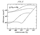
- Figure 3 is a thermopiezic curve for absorption of ammonia gas by Y2Fe17 at an atmosphere of approximately 1 bar.
- the curves of heating demonstrate an increase in pressure due to uptake of nitrogen from the ammonia. There is an increase in weight after heating the sample to 550 o C which is attributed to nitrogen absorption.
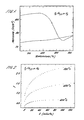
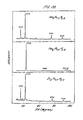
- Figure 4 shows 57Fe Mössbauer spectra at room temperature of Y2Fe17 before (a) and after (b) heating to 500 o C in 1 bar ammonia.
- the changes in Curie temperature and magnetic moment are reflected in the 57Fe Mossbauer spectra in which the average hyperfine field at 20 o C, ⁇ B hf > increases from 10 Tesla for Y2Fe17 to 30 Tesla for Y2Fe17N 2.6 ;
- Figure 5 shows the X-ray diffraction patterns of Y2Fe17 powder heated in a thermopiezic analyser in nitrogen at 10 o C/minute up to the temperatures of 500 o C, 550 o C, 600 o C, 700 o C and 850 o C. Powders of the formula R2Fe17 where R is another rare earth element behave similarly.
- the figure shows the appearance of a phase with expanded lattice parameters which co-exists with the unexpanded phase after treatment up to 550 o C.
- the Y2Fe17N 2.6 phase forms clearly at 600 o C and on heating up to 700 o C or above the alloy decomposes to YN and ⁇ Fe;
- Figure 6 shows X-ray diffraction patterns of Y2Fe17 powder after heating in nitrogen gas isothermally at 500 o C for two hours.
- the extended heat treatment produces the Y2Fe17N 2.6 compound at a lower temperature than shown in the previous figure but further heat treatment to 850 o C results in decomposition to YN and ⁇ Fe.
- Figure 7 is a thermopiezic curve for Y2Fe17C 1.0 heated from room temperature in an atmosphere of approximately 1 bar ammonia. Again an increase in pressure at about 370 o C is observed;
- Figure 8 shows the dependence of the Curie temperature (a) Tc( o C) and the unit cell volume of the lattice (b) V( ⁇ 3) on the maximum heating temperature Tm for Y2Fe17C.
- Figure 9 shows Mossbauer spectra at room temperature of Y2Fe17C 1.0 before (a) and after (b) heating in 1 bar ammonia at 550 o C.
- the average hyperfine field at 18 o C ⁇ B hf > increases from 25.3 Tesla to 30.8 Tesla after the ammonia treatment;
- Figure 10 is a thermopiezic curve for Sm2Fe17C 1.1 heated from room temperature in an atmosphere of approximately 1 bar ammonia. Again an increase in pressure is shown at about 350 o C. Analysis of the sample after heating to 600 o C reveals that the material retains the rhombohedral (Th2Zn17-type) structure with increased lattice parameters. From the increase in mass the nitrogen content is estimated to be 1.1 nitrogen atoms per Sm2Fe17C 1.1 formula unit;
- Figure 11 is an X-ray diffraction pattern of Sm2Fe17C 1.1 N 1.1 powder before (a) and after (b) orientation in an applied field of 1.2 Tesla for one hour.
- the figure demonstrates the strong uniaxial anisotropy possessed in particular where R is samarium;
- Figure 12 shows magnetization curves at 18 o C of oriented samples of Sm2Fe17C 1.1 before (a) and after (b) treatment in 1 bar ammonia up to 600 o C. Curves are shown for the field applied parallel ( ⁇ ) and perpendicular ( ⁇ ) to the axis of orientation. From these magnetization curves the values for ⁇ o M s shown in Table 2 and B a shown in Table 3 are obtained;
- Figure 13 shows the X-ray diffraction patterns of a) Sm2Fe17 powder with an average particle size of 1 ⁇ m and b) the same powder heated at 500 o C in nitrogen gas for two hours to form Sm2Fe17N 2.4 ;
- Figures 14a and b show the radial distribution functions deduced from extended X-ray absorption fine structure data on the same samples as Figure 13.
- the peak appearing at 2.5 ⁇ shows the presence of approximately three nitrogen atoms at a distance 2.5 A from a samarium atom in the nitride;
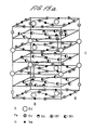
- Figures 15a and b show the crystal structure of the rhombohedral and hexagonal 2:17 structure, indicating the sites occupied by nitrogen;
- Figure 15a is the rhombohedral crystal structure and
- Figure 15b is the hexagonal crystal structure.
- Large circles represent rare earths, small shaded circles represent iron and small black circles represent nitrogen sites 9e or 6h.
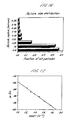
- Figure 16 is a histogram of the particle size distribution of a typical Sm2Fe17 powder used for nitrogen absorption
- Figure 17 shows the variation of the diffusion coefficient for nitrogen in the Sm2Fe17 powder as a function of inverse temperature.
- Figure 18 shows magnetization curves at 18°C for an oriented sample of Sm2Fe17N 2.3 after treatment with ammonia. Again curves are shown for the field applied parallel ( ⁇ ) and perpendicular ( ⁇ ) to the axis of orientation. From these the values of the anisotropy field B a are obtained as shown in Table 3. The value of B a for Sm2Fe17N 2.3 is given as >12.0 Tesla but in fact the curves shown in the figure indicate it may be as high as 20 Tesla;
- Figure 19(a) is a thermopiezic curve for a powder made from a cast ingot of Sm2Fe17 heated in nitrogen.
- Figure 19(b) is a thermopiezic curve for a powder made from an ingot and annealed for 100 hours at 950 o C and heated in nitrogen. The differences in the two sets of curves clearly demonstrate that the treatment temperature required to form the R2Fe17N b phase varies depending on the metallurgical composition of the ingot used to make the powder;
- Figure 20 shows X-ray diffraction patterns of the compounds Nd2Fe17N 2.3 , Sm2Fe17N 2.3 and Er2Fe17N 2.7 after an applied field of 1.2 Tesla.
- Sm2Fe17N 2.3 the c-axis is aligned parallel to the applied field indicating strong uniaxial anisotropy.
- R is Nd or Er there is a tendency for the c-axis to be aligned perpendicular to the direction of the applied magnetic field;
- Figure 21 shows the crystal structure of the tetragonal 1:12 compound showing sites occupied by nitrogen.
- the coding of the circles is as described for Figures 15a and 15b;
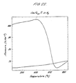
- Figure 22 shows a thermopiezic trace for absorption of nitrogen gas by Sm(Fe11Ti). The material was heated at a rate of 10 o C/minute at approximately 1 bar nitrogen. The figure demonstrates that the optimum temperature range for operation of the process is similar to that of the R2Fe17 compounds;
- Figure 23 shows room temperature 57 Mössbauer spectra of Sm(Fe11Ti) before (a) and after (b) heating in a nitrogen containing gas in accordance with the invention.
- the average hypefine field increases from 25.5 Tesla in (a) to 29.1 Tesla in (b), reflecting the changes in Curie temperature and iron magnetic moment.
- Figure 24 shows X-ray diffraction patterns of powders of Sm(Fe11Ti) (a) and Sm(Fe11Ti)N 0.8 (b) oriented in a magnetic field of 1.2 Tesla.
- the strong uniaxial anisotropy of Sm(Fe11Ti) is transformed to easy-plane anisotropy in the interstitial nitride SmFe11TiN 0.8 demonstrating a change in sign of the second-order crystal field coefficient A20 from negative to positive.
- Figure 25 is an illustration of interstitial nitrogen atoms around the rare earth in the rhombohedral or hexagonal 2.17 structure (a) and in the tetragonal 1.12 structure (b).
- the electric field gradient experienced by the rare-earth, quantified in the parameter A20, is mainly produced by surrounding interstitial atoms in the materials of the invention. It is negative for the configuration of the 2.17 compounds and positive for configuration of the 1.12 compounds;
- Figure 26 illustrates some of the effects of cobalt substitution for iron in materials of the invention having the rhombohedral or hexagonal crystal structure.
- Figure 26(a) indicates the nitrogen content achieved by treating finely-ground powders of the R2(Fe 17-c Co c )N b type formula where c is the number of cobalt atoms in nitrogen gas at temperatures ranging from 400-600 o C.
- Figure 26(c) shows that the transition metal substituents make a positive contribution to the anisotropy when c is >0.1;
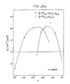
- Figure 27 is an illustration of the development of hysteresis in a powder of Sm2Fe17N 2.3 comprising first and second quadrant demagnetizing curves of samples aligned and magnetized in a pulsed field of 8 Tesla.
- the data represented are as follows:-
- Figure 27 indicates the magnetic properties of permanent magnets produced from the magnetic materials of the invention and methods by which the coercivity and hysteresis may be developed.
- the material is milled with 15 wt % Zn and heated to 400 o C to produce a magnet having a coercivity of 0.5 Tesla and a maximum energy product of 86KJm ⁇ 3.
- thin films of materials of the invention may be exploited for magnetic or magneto-optic recording.
Landscapes
- Chemical & Material Sciences (AREA)
- Crystallography & Structural Chemistry (AREA)
- Inorganic Chemistry (AREA)
- Engineering & Computer Science (AREA)
- Power Engineering (AREA)
- Hard Magnetic Materials (AREA)
- Powder Metallurgy (AREA)
Applications Claiming Priority (6)
| Application Number | Priority Date | Filing Date | Title |
|---|---|---|---|
| IE135990 | 1990-04-18 | ||
| IE320190 | 1990-09-04 | ||
| IE320190 | 1990-09-04 | ||
| IE67191 | 1991-02-28 | ||
| IE67191 | 1991-02-28 | ||
| IE135990A IE76721B1 (en) | 1990-09-04 | 1991-04-18 | Rare-earth based magnetic materials production process and use |
Publications (3)
| Publication Number | Publication Date |
|---|---|
| EP0453270A2 true EP0453270A2 (de) | 1991-10-23 |
| EP0453270A3 EP0453270A3 (de) | 1991-11-27 |
| EP0453270B1 EP0453270B1 (de) | 1996-04-10 |
Family
ID=27270319
Family Applications (1)
| Application Number | Title | Priority Date | Filing Date |
|---|---|---|---|
| EP91303442A Expired - Lifetime EP0453270B1 (de) | 1990-04-18 | 1991-04-17 | Seltenerd-basierte magnetische Materialien, Herstellungsverfahren und Anwendung |
Country Status (7)
| Country | Link |
|---|---|
| EP (1) | EP0453270B1 (de) |
| JP (1) | JPH06349612A (de) |
| AT (1) | ATE136680T1 (de) |
| CA (1) | CA2040686A1 (de) |
| DE (1) | DE69118577T2 (de) |
| IE (1) | IE76721B1 (de) |
| PT (1) | PT97411A (de) |
Cited By (13)
| Publication number | Priority date | Publication date | Assignee | Title |
|---|---|---|---|---|
| DE4116857A1 (de) * | 1991-05-23 | 1992-11-26 | Siemens Ag | Magnetmaterial mit thmn(pfeil abwaerts)1(pfeil abwaerts)(pfeil abwaerts)2(pfeil abwaerts)-kristallstruktur und verfahren zu dessen herstellung |
| EP0468317A3 (en) * | 1990-07-25 | 1992-12-09 | Siemens Aktiengesellschaft | Method for the preparation of magnetic material based an the sm-fe-n substance system |
| EP0538643A1 (de) * | 1991-10-24 | 1993-04-28 | Vacuumschmelze GmbH | Verfahren zur Herstellung eines N-haltigen Dauermagneten, wie Sm2Fe17N durch Zusatz einer festen, N-haltigen Verbindung |
| EP0532701A4 (en) * | 1990-06-08 | 1993-07-14 | Sps Technologies, Inc. | Improved magnetic materials and process for producing the same |
| DE4237346C1 (de) * | 1992-11-05 | 1993-12-02 | Goldschmidt Ag Th | Verfahren zur Herstellung von Legierungen der Seltenen Erden des Typs SE¶2¶Fe¶1¶¶7¶¶-¶¶x¶M¶x¶N¶y¶ |
| US5288339A (en) * | 1990-07-25 | 1994-02-22 | Siemens Aktiengesellschaft | Process for the production of magnetic material based on the Sm-Fe-N system of elements |
| WO1994005021A1 (en) * | 1992-08-21 | 1994-03-03 | Martinex R&D Inc. | Permanent magnet material containing a rare-earth element, iron, nitrogen and carbon |
| US5403407A (en) * | 1993-04-08 | 1995-04-04 | University Of Delaware | Permanent magnets made from iron alloys |
| US5769969A (en) * | 1995-11-28 | 1998-06-23 | Sumitomo Metal Mining Co., Ltd. | Rare earth-iron-nitrogen magnet alloy |
| US20110133112A1 (en) * | 2009-11-30 | 2011-06-09 | Hitachi, Ltd. | Ferromagnetic compound magnet |
| US7998283B2 (en) | 2006-09-19 | 2011-08-16 | Yingchang Yang | Rare earth anisotropic hard magnetic material and processes for producing magnetic powder and magnet using the same |
| US8793387B2 (en) | 2007-08-08 | 2014-07-29 | Blackberry Limited | Method for pre-fetching data chunks of an email attachment on a portable electronic device |
| JP2015156436A (ja) * | 2014-02-20 | 2015-08-27 | 日立金属株式会社 | 強磁性合金およびその製造方法 |
Families Citing this family (1)
| Publication number | Priority date | Publication date | Assignee | Title |
|---|---|---|---|---|
| US10062482B2 (en) | 2015-08-25 | 2018-08-28 | GM Global Technology Operations LLC | Rapid consolidation method for preparing bulk metastable iron-rich materials |
Family Cites Families (3)
| Publication number | Priority date | Publication date | Assignee | Title |
|---|---|---|---|---|
| US4402770A (en) * | 1981-10-23 | 1983-09-06 | The United States Of America As Represented By The Secretary Of The Navy | Hard magnetic alloys of a transition metal and lanthanide |
| JPS60131949A (ja) * | 1983-12-19 | 1985-07-13 | Hitachi Metals Ltd | 鉄−希土類−窒素系永久磁石 |
| DE4025277A1 (de) * | 1990-08-09 | 1992-02-13 | Siemens Ag | Verfahren zur herstellung eines anisotropen magnetmaterials auf basis des stoffsystems sm-fe-n |
-
1991
- 1991-04-17 DE DE69118577T patent/DE69118577T2/de not_active Expired - Fee Related
- 1991-04-17 AT AT91303442T patent/ATE136680T1/de active
- 1991-04-17 EP EP91303442A patent/EP0453270B1/de not_active Expired - Lifetime
- 1991-04-17 CA CA002040686A patent/CA2040686A1/en not_active Abandoned
- 1991-04-18 JP JP3086632A patent/JPH06349612A/ja active Pending
- 1991-04-18 IE IE135990A patent/IE76721B1/en not_active IP Right Cessation
- 1991-04-18 PT PT97411A patent/PT97411A/pt not_active Application Discontinuation
Cited By (17)
| Publication number | Priority date | Publication date | Assignee | Title |
|---|---|---|---|---|
| EP0532701A4 (en) * | 1990-06-08 | 1993-07-14 | Sps Technologies, Inc. | Improved magnetic materials and process for producing the same |
| EP0468317A3 (en) * | 1990-07-25 | 1992-12-09 | Siemens Aktiengesellschaft | Method for the preparation of magnetic material based an the sm-fe-n substance system |
| US5288339A (en) * | 1990-07-25 | 1994-02-22 | Siemens Aktiengesellschaft | Process for the production of magnetic material based on the Sm-Fe-N system of elements |
| DE4116857A1 (de) * | 1991-05-23 | 1992-11-26 | Siemens Ag | Magnetmaterial mit thmn(pfeil abwaerts)1(pfeil abwaerts)(pfeil abwaerts)2(pfeil abwaerts)-kristallstruktur und verfahren zu dessen herstellung |
| EP0538643A1 (de) * | 1991-10-24 | 1993-04-28 | Vacuumschmelze GmbH | Verfahren zur Herstellung eines N-haltigen Dauermagneten, wie Sm2Fe17N durch Zusatz einer festen, N-haltigen Verbindung |
| US5720828A (en) * | 1992-08-21 | 1998-02-24 | Martinex R&D Inc. | Permanent magnet material containing a rare-earth element, iron, nitrogen and carbon |
| WO1994005021A1 (en) * | 1992-08-21 | 1994-03-03 | Martinex R&D Inc. | Permanent magnet material containing a rare-earth element, iron, nitrogen and carbon |
| DE4237346C1 (de) * | 1992-11-05 | 1993-12-02 | Goldschmidt Ag Th | Verfahren zur Herstellung von Legierungen der Seltenen Erden des Typs SE¶2¶Fe¶1¶¶7¶¶-¶¶x¶M¶x¶N¶y¶ |
| EP0596385A1 (de) * | 1992-11-05 | 1994-05-11 | Th. Goldschmidt AG | Verfahren zur Herstellung von Legierungen der Seltenen Erden des Typs SE2Fe17-xTMxNy |
| US5482572A (en) * | 1992-11-05 | 1996-01-09 | Th. Goldschmidt Ag | Method for the preparation of alloys of the rare earth metals of the SE.sub. Fe17-x TMx Ny type |
| US5403407A (en) * | 1993-04-08 | 1995-04-04 | University Of Delaware | Permanent magnets made from iron alloys |
| US5769969A (en) * | 1995-11-28 | 1998-06-23 | Sumitomo Metal Mining Co., Ltd. | Rare earth-iron-nitrogen magnet alloy |
| US7998283B2 (en) | 2006-09-19 | 2011-08-16 | Yingchang Yang | Rare earth anisotropic hard magnetic material and processes for producing magnetic powder and magnet using the same |
| US8793387B2 (en) | 2007-08-08 | 2014-07-29 | Blackberry Limited | Method for pre-fetching data chunks of an email attachment on a portable electronic device |
| US20110133112A1 (en) * | 2009-11-30 | 2011-06-09 | Hitachi, Ltd. | Ferromagnetic compound magnet |
| US8764917B2 (en) * | 2009-11-30 | 2014-07-01 | Hitachi, Ltd. | Ferromagnetic compound magnet |
| JP2015156436A (ja) * | 2014-02-20 | 2015-08-27 | 日立金属株式会社 | 強磁性合金およびその製造方法 |
Also Published As
| Publication number | Publication date |
|---|---|
| DE69118577D1 (de) | 1996-05-15 |
| PT97411A (pt) | 1992-01-31 |
| EP0453270A3 (de) | 1991-11-27 |
| EP0453270B1 (de) | 1996-04-10 |
| CA2040686A1 (en) | 1991-10-19 |
| IE76721B1 (en) | 1997-11-05 |
| ATE136680T1 (de) | 1996-04-15 |
| IE901359A1 (en) | 1991-11-06 |
| DE69118577T2 (de) | 1996-11-14 |
| JPH06349612A (ja) | 1994-12-22 |
Similar Documents
| Publication | Publication Date | Title |
|---|---|---|
| Katter et al. | Structural and hard magnetic properties of rapidly solidified Sm–Fe–N | |
| Kumar | RETM5 and RE2TM17 permanent magnets development | |
| EP0453270B1 (de) | Seltenerd-basierte magnetische Materialien, Herstellungsverfahren und Anwendung | |
| US6120620A (en) | Praseodymium-rich iron-boron-rare earth composition, permanent magnet produced therefrom, and method of making | |
| US5800728A (en) | Permanent magnetic material made of iron-rare earth metal alloy | |
| US5720828A (en) | Permanent magnet material containing a rare-earth element, iron, nitrogen and carbon | |
| EP0493019B1 (de) | Verfahren zur Modifizierung von Magnetmaterialien und Magnetmaterialien daraus | |
| US5478411A (en) | Magnetic materials and processes for their production | |
| US4854979A (en) | Method for the manufacture of an anisotropic magnet material on the basis of Fe, B and a rare-earth metal | |
| JP3073807B2 (ja) | 鉄−希土類系永久磁石材料およびその製造方法 | |
| Cheng et al. | Structure and magnetic anisotropy of Sm2Fe17− x Al x C (x= 2–8) compounds prepared by arc melting | |
| WO2000048209A1 (en) | Praseodymium-rich iron-boron-rare earth composition, permanent magnet produced therefrom, and method of making | |
| US5403407A (en) | Permanent magnets made from iron alloys | |
| JP2966169B2 (ja) | 希土類磁石並びに希土類磁石用合金粉末とその製造方法 | |
| JP2999648B2 (ja) | 希土類磁石並びに希土類磁石合金粉末とその製造方法 | |
| JPH0644526B2 (ja) | 希土類磁石の製造方法 | |
| JPH04260302A (ja) | 磁石粉末およびその製造方法ならびにボンディッド磁石 | |
| JP2951006B2 (ja) | 永久磁石材料およびその製造方法ならびにボンディッド磁石 | |
| JPH04254304A (ja) | Sm−Fe−N系磁石材料の製造方法 | |
| Pan et al. | Study of the coercivity of Pr (Mo, Fe) 12N x | |
| JPH04346607A (ja) | 永久磁石粉末の製造方法 | |
| JPH05247600A (ja) | 磁石材料とその製造方法 | |
| JPH04318152A (ja) | 希土類磁石材料およびその製造方法 | |
| JPH0142338B2 (de) | ||
| JPH0467325B2 (de) |
Legal Events
| Date | Code | Title | Description |
|---|---|---|---|
| PUAI | Public reference made under article 153(3) epc to a published international application that has entered the european phase |
Free format text: ORIGINAL CODE: 0009012 |
|
| PUAL | Search report despatched |
Free format text: ORIGINAL CODE: 0009013 |
|
| AK | Designated contracting states |
Kind code of ref document: A2 Designated state(s): AT BE CH DE DK ES FR GB GR IT LI LU NL SE |
|
| AK | Designated contracting states |
Kind code of ref document: A3 Designated state(s): AT BE CH DE DK ES FR GB GR IT LI LU NL SE |
|
| 17P | Request for examination filed |
Effective date: 19920311 |
|
| 17Q | First examination report despatched |
Effective date: 19920619 |
|
| GRAH | Despatch of communication of intention to grant a patent |
Free format text: ORIGINAL CODE: EPIDOS IGRA |
|
| GRAA | (expected) grant |
Free format text: ORIGINAL CODE: 0009210 |
|
| AK | Designated contracting states |
Kind code of ref document: B1 Designated state(s): AT BE CH DE DK ES FR GB GR IT LI LU NL SE |
|
| PG25 | Lapsed in a contracting state [announced via postgrant information from national office to epo] |
Ref country code: IT Free format text: LAPSE BECAUSE OF FAILURE TO SUBMIT A TRANSLATION OF THE DESCRIPTION OR TO PAY THE FEE WITHIN THE PRESCRIBED TIME-LIMIT;WARNING: LAPSES OF ITALIAN PATENTS WITH EFFECTIVE DATE BEFORE 2007 MAY HAVE OCCURRED AT ANY TIME BEFORE 2007. THE CORRECT EFFECTIVE DATE MAY BE DIFFERENT FROM THE ONE RECORDED. Effective date: 19960410 Ref country code: BE Effective date: 19960410 Ref country code: DK Effective date: 19960410 Ref country code: CH Free format text: LAPSE BECAUSE OF FAILURE TO SUBMIT A TRANSLATION OF THE DESCRIPTION OR TO PAY THE FEE WITHIN THE PRESCRIBED TIME-LIMIT Effective date: 19960410 Ref country code: ES Free format text: THE PATENT HAS BEEN ANNULLED BY A DECISION OF A NATIONAL AUTHORITY Effective date: 19960410 Ref country code: NL Free format text: LAPSE BECAUSE OF FAILURE TO SUBMIT A TRANSLATION OF THE DESCRIPTION OR TO PAY THE FEE WITHIN THE PRESCRIBED TIME-LIMIT Effective date: 19960410 Ref country code: AT Effective date: 19960410 Ref country code: LI Free format text: LAPSE BECAUSE OF FAILURE TO SUBMIT A TRANSLATION OF THE DESCRIPTION OR TO PAY THE FEE WITHIN THE PRESCRIBED TIME-LIMIT Effective date: 19960410 Ref country code: GR Free format text: LAPSE BECAUSE OF FAILURE TO SUBMIT A TRANSLATION OF THE DESCRIPTION OR TO PAY THE FEE WITHIN THE PRESCRIBED TIME-LIMIT Effective date: 19960410 |
|
| REF | Corresponds to: |
Ref document number: 136680 Country of ref document: AT Date of ref document: 19960415 Kind code of ref document: T |
|
| PG25 | Lapsed in a contracting state [announced via postgrant information from national office to epo] |
Ref country code: LU Free format text: LAPSE BECAUSE OF NON-PAYMENT OF DUE FEES Effective date: 19960430 |
|
| ET | Fr: translation filed | ||
| REF | Corresponds to: |
Ref document number: 69118577 Country of ref document: DE Date of ref document: 19960515 |
|
| PG25 | Lapsed in a contracting state [announced via postgrant information from national office to epo] |
Ref country code: SE Effective date: 19960710 |
|
| NLV1 | Nl: lapsed or annulled due to failure to fulfill the requirements of art. 29p and 29m of the patents act | ||
| REG | Reference to a national code |
Ref country code: CH Ref legal event code: PL |
|
| PLBE | No opposition filed within time limit |
Free format text: ORIGINAL CODE: 0009261 |
|
| STAA | Information on the status of an ep patent application or granted ep patent |
Free format text: STATUS: NO OPPOSITION FILED WITHIN TIME LIMIT |
|
| 26N | No opposition filed | ||
| PGFP | Annual fee paid to national office [announced via postgrant information from national office to epo] |
Ref country code: GB Payment date: 19980130 Year of fee payment: 8 |
|
| PGFP | Annual fee paid to national office [announced via postgrant information from national office to epo] |
Ref country code: FR Payment date: 19980210 Year of fee payment: 8 |
|
| PGFP | Annual fee paid to national office [announced via postgrant information from national office to epo] |
Ref country code: DE Payment date: 19980430 Year of fee payment: 8 |
|
| PG25 | Lapsed in a contracting state [announced via postgrant information from national office to epo] |
Ref country code: GB Free format text: LAPSE BECAUSE OF NON-PAYMENT OF DUE FEES Effective date: 19990417 |
|
| GBPC | Gb: european patent ceased through non-payment of renewal fee |
Effective date: 19990417 |
|
| PG25 | Lapsed in a contracting state [announced via postgrant information from national office to epo] |
Ref country code: FR Free format text: LAPSE BECAUSE OF NON-PAYMENT OF DUE FEES Effective date: 19991231 |
|
| REG | Reference to a national code |
Ref country code: FR Ref legal event code: ST |
|
| PG25 | Lapsed in a contracting state [announced via postgrant information from national office to epo] |
Ref country code: DE Free format text: LAPSE BECAUSE OF NON-PAYMENT OF DUE FEES Effective date: 20000201 |