EP0453501B1 - Coupleurs en etoile moules par injection et procedes de fabrication - Google Patents
Coupleurs en etoile moules par injection et procedes de fabrication Download PDFInfo
- Publication number
- EP0453501B1 EP0453501B1 EP90902528A EP90902528A EP0453501B1 EP 0453501 B1 EP0453501 B1 EP 0453501B1 EP 90902528 A EP90902528 A EP 90902528A EP 90902528 A EP90902528 A EP 90902528A EP 0453501 B1 EP0453501 B1 EP 0453501B1
- Authority
- EP
- European Patent Office
- Prior art keywords
- channels
- coupler
- injection molded
- star
- channel
- Prior art date
- Legal status (The legal status is an assumption and is not a legal conclusion. Google has not performed a legal analysis and makes no representation as to the accuracy of the status listed.)
- Expired - Lifetime
Links
- 238000002347 injection Methods 0.000 title claims abstract description 36
- 239000007924 injection Substances 0.000 title claims abstract description 36
- 238000000034 method Methods 0.000 title claims abstract description 10
- 239000011162 core material Substances 0.000 claims abstract description 39
- 239000000463 material Substances 0.000 claims abstract description 22
- 238000005253 cladding Methods 0.000 claims abstract description 21
- 239000000835 fiber Substances 0.000 claims abstract description 17
- 230000003287 optical effect Effects 0.000 claims abstract description 16
- 238000001746 injection moulding Methods 0.000 claims abstract description 8
- 230000013011 mating Effects 0.000 claims abstract description 6
- 229920003229 poly(methyl methacrylate) Polymers 0.000 claims description 14
- 239000004926 polymethyl methacrylate Substances 0.000 claims description 14
- 238000004891 communication Methods 0.000 claims description 6
- 238000005516 engineering process Methods 0.000 abstract description 3
- 239000013307 optical fiber Substances 0.000 description 9
- 230000008878 coupling Effects 0.000 description 3
- 238000010168 coupling process Methods 0.000 description 3
- 238000005859 coupling reaction Methods 0.000 description 3
- 239000004033 plastic Substances 0.000 description 3
- 229920003023 plastic Polymers 0.000 description 3
- 230000005540 biological transmission Effects 0.000 description 2
- 238000009826 distribution Methods 0.000 description 2
- 239000011521 glass Substances 0.000 description 2
- 238000000465 moulding Methods 0.000 description 2
- 239000004020 conductor Substances 0.000 description 1
- 230000036039 immunity Effects 0.000 description 1
- 238000003780 insertion Methods 0.000 description 1
- 230000037431 insertion Effects 0.000 description 1
- 238000005342 ion exchange Methods 0.000 description 1
- 238000002955 isolation Methods 0.000 description 1
- 230000007774 longterm Effects 0.000 description 1
- 238000003754 machining Methods 0.000 description 1
- 238000004519 manufacturing process Methods 0.000 description 1
- 238000012986 modification Methods 0.000 description 1
- 230000004048 modification Effects 0.000 description 1
- 230000000644 propagated effect Effects 0.000 description 1
- 230000009467 reduction Effects 0.000 description 1
- 238000010079 rubber tapping Methods 0.000 description 1
- 239000007787 solid Substances 0.000 description 1
Images

Classifications
-
- G—PHYSICS
- G02—OPTICS
- G02B—OPTICAL ELEMENTS, SYSTEMS OR APPARATUS
- G02B6/00—Light guides; Structural details of arrangements comprising light guides and other optical elements, e.g. couplings
- G02B6/24—Coupling light guides
- G02B6/26—Optical coupling means
- G02B6/28—Optical coupling means having data bus means, i.e. plural waveguides interconnected and providing an inherently bidirectional system by mixing and splitting signals
- G02B6/2804—Optical coupling means having data bus means, i.e. plural waveguides interconnected and providing an inherently bidirectional system by mixing and splitting signals forming multipart couplers without wavelength selective elements, e.g. "T" couplers, star couplers
-
- B—PERFORMING OPERATIONS; TRANSPORTING
- B29—WORKING OF PLASTICS; WORKING OF SUBSTANCES IN A PLASTIC STATE IN GENERAL
- B29D—PRODUCING PARTICULAR ARTICLES FROM PLASTICS OR FROM SUBSTANCES IN A PLASTIC STATE
- B29D11/00—Producing optical elements, e.g. lenses or prisms
- B29D11/0074—Production of other optical elements not provided for in B29D11/00009- B29D11/0073
- B29D11/0075—Connectors for light guides
Definitions
- the present invention is directed to star-couplers in which a plurality of optical fibers are connected together.
- the invention is also directed to methods for making the couplers.
- optical fibers offer many significant advantages compared with metallic conductors, including: long distance transmission without the need for repeaters, immunity from electromagnetic interference, cross-talk and ground loop, high bandwidth capabilities, small size and weight, high degree of intercept security and dielectric isolation, and long term cost reduction. These desirable features of optical fibers have strongly stimulated efforts both in fiber optics and in supporting technologies such as fiber optic coupling.
- Fiber optic couplers provide for feeding and tapping of optical energy.
- Fiber optic couplers are widely used in multi-terminal communication systems and data buses. In these applications, a common optical path provides communication among a plurality of terminals. Typically, each terminal communicates to every other terminal and provides information on a time shared basis. The effectiveness of such systems depends on characteristics of the optical fibers themselves as well as on the coupling devices employed to share and distribute information.
- a star-coupler is a device which distributes the power on any one of several incoming channels to every one of its outgoing channels. Star-couplers are intended to have minimal insertion losses and a substantially uniform power distribution over the outgoing channels. Thus, a system employing a star-coupler and a plurality of terminals represents a parallel distribution system.
- Star couplers are particularly useful in the field of optical communications for coupling together a plurality of optic fibers to form a network.
- the couplers have a plurality of incoming channels, a plurality of outgoing channels and a mixing zone which couples optical signals from any one of the incoming channels to all of the outgoing channels.
- the mixing zone may comprise optic fibers which are tapered and fused together or wave guides in solid blocks of glass. These glass blocks usually have wave guides specially prepared by ion exchange processes or otherwise, and the fibers are aligned with the wave guides.
- the incoming and outgoing channels are typically bundles of optical fibers. Information in the form of light pulses as signals from any single optical fiber of the input fiber optic bundle is transmitted via the coupler to each of the optical fibers in the output fiber optic bundle.
- the coupler comprises a block of plastic or other suitable material that is injection molded to form input and output connectors.
- the core is made of a material having an index of refraction that is higher than that of the block.
- the core is made of pure polymethylmethacrylate (PMMA) and the cladding is made of fluorinated PMMA. Because the coupler is made by molding techniques, fabrication costs are relatively low compared to those of conventional star-couplers.
- the input and output connectors are defined in the injection molding process to have a shape which facilitates their connection to conventional optic fibers and connectors. As a result, the star-coupler can readily be connected to the fibers which it is to couple.
- the coupler is injection molded following any one of a number of techniques.
- the coupler can be formed by injection molding a bottom half and a top half with a material that has a refractive index similar to that of the cladding. Channels are defined in the bottom and/or top halves for receiving the core material, the two halves are fitted together with the channels forming a cavity therebetween and then the core material is injection molded into the cavity defined between the cladding halves.
- an illustrative embodiment of the invention comprises four input ports 12, 14, 16, 18, a mixing channel or zone 20 and four output ports 22, 24, 26, 28.
- Input ports 12, 14, 16, 18 are connected to mixing zone 20 by channels 13, 15, 17, 19, respectively.
- Mixing zone 20 is connected to ports 22, 24, 26, 28 by channels 23, 25, 27, 29, respectively.
- channels and the mixing zone propagate optical signals.
- light input to any of the input ports will be transmitted to mixing element 20 where it is then distributed to all of the output ports.
- light input at input port 12 is transmitted by channel 13 to mixing zone 20.
- Mixing zone 20 then distributes the light from port 12 to each of output ports 22, 24, 26, 28 along channels 23, 25, 27, 29, respectively.
- ports 12, 22 are corresponding input and output ports, i.e., they are each connected to the same terminal or data communications device.
- ports 14, 24, ports, 16, 26 and ports 18, 28 are each connected to the same device.
- the channels are schematically depicted and are not drawn to scale.
- FIG. 2 there is schematically depicted a further embodiment of a 4 x 4 star-coupler.
- This particular embodiment comprises input ports 35, 40, 45, 50 and output ports 39, 44, 49, 54 which are located opposite ports 35, 40, 45, 50, respectively.
- Input port 35 and output port 39 are preferably connected to the same terminal or device.
- ports 40, 44, ports 45, 49 and ports 50, 54 are each connected to the same terminal or device.
- Each of the input ports is provided with a separate channel to each of the output ports, except the corresponding output port connected to the same device, illustratively, the output port directly opposite that input port.
- input port 35 is provided with channel 36 to output port 44, channel 37 to output port 49 and channel 38 to output port 54.
- input port 35 is not provided with a channel to its opposite corresponding output port, namely, port 39.
- Fig. 3 is a schematic illustration of another embodiment of the invention comprising input ports 60, 65, 70, 75 and output ports 80, 85, 90, 95.
- a binary tree network connects all input ports to a mixing channel and a second binary tree network connects the mixing channel to all output ports.
- light from input port 60 enters channel 61, then channel 63 and then channel 100. From channel 100, the light is distributed to channels 83 and 93. From channel 83, the light is distributed to channels 81, 82 which are coupled to ports 80, 85, respectively. Similarly, from channel 93, the light is distributed to channels 91, 92 which are coupled to ports 90, 95, respectively.
- Light input to any of input ports 65, 70, 75 is similarly provided to all of the output ports 80, 85, 90, 95.
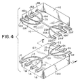
- FIG. 4 there is depicted a perspective view of the device schematically illustrated in Fig. 1.
- This 4 x 4 star-coupler comprises a first section 110 and a mating second section 120.
- these sections are mirror images of each other and each forms one half of the star-coupler.
- Each of sections 110 and 120 is fabricated by injection molding and comprises a block-like structure having a planar face 112, 122, respectively.
- a network of channels preferably semicircular in shape, is formed in each of these faces 112, 122. The configuration of this network has been described in conjunction with Fig. 1.
- Attachment of section 110 to section 120 thus provides a network of circular channels in which each input port is connected to all of the output ports.
- Each input port and each output port is formed by two port portions, for example 12 and 12A.
- Sections 110, 120 are each constructed from a suitable plastic optic cladding material. Further, the entire network of channels is filled with a suitable fiber optic core material prior to attachment of section 110 to section 120. Application of force (by means not shown) to the sections will cause excess core material to be expelled from between the sections. Alternatively, sections 110, 120 may first be joined together and then core material injected into the ports to entirely fill the channels. The cladding material has a lower index of refraction than the core material. Thus, light is propagated in the core material and guided and confined therein by the cladding material.
- a suitable material for the cladding is fluorinated polymethylmethacrylate (PMMA) while a suitable material for the core is pure PMMA.
- the input and output ports are formed during injection molding and are appropriately aligned with respect to the channel(s) to which they are attached. These ports are adapted to be easily connected to known connectors and preferably do not require further machining. The particular shape and configuration of the ports depend on the nature of the connector to which it is to be connected.
- sections 110, 120 are constructed from practically any material which can be injection molded.
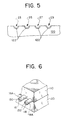
- Fig. 5 illustrates such an embodiment in the form of a modified cross-sectional view of Fig. 4.
- a suitable cladding material 122 is applied to the surfaces of section 120 defining channels 23, 25, 27, 29 therein. Core material is then placed within the channels as discussed in conjunction with the description of Fig. 4.
- Fig. 6 illustrates a portion of a star-coupler assembled in accordance with the invention. Specifically, a first input port comprises halves 16, 16A and core 130 while a second input port comprises halves 18, 18A and core 132.
- a one-piece structure having a suitable network of channels can be formed by injection molding.
- the two mating halves which form a star-coupler need not be mirror images of each other, for example, one may contain a channel of more than half of the cross-sectional area of the resultant channel and the other may contain less than half of the cross-sectional area or none of the resultant channel.
- the channel may be non-circular.
- the channel can be a rectangular or square-walled channel with a slight taper for mold release and so on.
- the invention is not limited to the disclosed 4 x 4 star-couplers, but may be practiced with star-couplers having any practical number of ports.
- injection molded fiber optic connectors may be provided to simply connect together two optical fibers and not interconnect various ports and channels as in a conventional star-coupler.
Landscapes
- Physics & Mathematics (AREA)
- Engineering & Computer Science (AREA)
- General Physics & Mathematics (AREA)
- Optics & Photonics (AREA)
- Health & Medical Sciences (AREA)
- Manufacturing & Machinery (AREA)
- Ophthalmology & Optometry (AREA)
- Mechanical Engineering (AREA)
- Optical Integrated Circuits (AREA)
- Injection Moulding Of Plastics Or The Like (AREA)
- Moulds For Moulding Plastics Or The Like (AREA)
Claims (24)
- Coupleur en étoile moulé par injection, comprenant:un bloc moulé par injection (10) ayant plusieurs canaux (13, 15, 17, 19, 23, 25, 27, 29) dans celui-ci, lesdits canaux se terminant aux faces avant et arrière du bloc,un matériau d'âme pour transmettre des signaux optiques, ledit matériau d'âme ayant un indice de réfraction supérieur à celui du matériau formant le bloc, ledit matériau d'âme remplissant lesdits canaux dans ledit bloc, de façon que la lumière soit guidée et confinée dans ceux-ci.caractérisé en ce que lesdits canaux forment un coupleur en étoile NxN,en ce qu'il est prévu plusieurs connecteurs d'entrée moulés par injection (12, 14, 16, 18) destinés à introduire des signaux optiques. lesdits connecteurs d'entrée étant formés par de saillies d'une pièce partant de la face avant du bloc et entourant chacune une partie terminale d'un canal, eten ce qu'il est prévu plusieurs connecteurs de sortie moulés par injection (22, 24, 26, 28) destinés à fournir des signaux optiques, lesdits connecteurs de sortie étant formés de saillies d'une pièce partant de la face arrière du bloc et entourant chacune une partie terminale d'un canal.
- Coupleur en étoile moulé par injection selon la revendication 1, dans lequel ledit matériau d'âme est le polyméthacrylate de méthyle (PMMA) et le matériau de recouvrement est le PMMA fluoré.
- Coupleur en étoile moulé par injection selon la revendication 1 dans lequel une couche de matériau de recouvrement ayant un indice de réfraction inférieur à l'indice de réfraction dudit matériau d'âme est disposé sur les surfaces dudit bloc formant lesdits canaux dans ledit bloc, de manière à former une structure de recouvrement entourant ledit matériau d'âme.
- Coupleur en étoile moulé par injection selon la revendication 3, dans lequel ledit matériau d'âme est du polyméthacrylate de méthyle (PMMA) et ledit matériau de recouvrement est le PMMA fluoré.
- Coupleur en étoile moulé par injection selon la revendication 1, dans lequel lesdits plusieurs canaux dans ledit bloc comprennent un canal de mélange (20), un canal partant de chacun desdits connecteurs d'entrée vers ledit canal de mélange et un canal partant dudit canal de mélange vers chacun desdits connecteurs de sortie.
- Coupleur en étoile moulé par injection selon la revendication 1, dans lequel lesdits plusieurs canaux dans ledit bloc comprennent un canal partant de chaque connecteur d'entrée vers chacun desdits connecteurs de sortie.
- Coupleur en étoile moulé par injection selon la revendication 1, dans lequel lesdits plusieurs canaux dans ledit bloc comprennent un canal partant de chacun desdits connecteurs d'entrée vers chacun desdits connecteurs de sortie, sauf qu'un canal n'est pas prévu depuis chaque connecteur d'entrée vers son connecteur de sortie correspondant connecté au même dispositif de communication.
- Coupleur en étoile moulé par injection selon la revendication 1, dans lequel lesdits canaux dans ledit bloc comprennent un premier réseau non maillé binaire, connectant tous lesdits connecteurs d'entrée à un canal de mélange (20; 100) et un réseau non maillé binaire secondaire, connectant ledit canal de mélange (20; 100) à tous lesdits connecteurs de sortie.
- Coupleur en étoile moulé par injection selon la revendication 1, dans lequel lesdits plusieurs canaux ont une section transversale circulaire.
- Connecteur en étoile moulé par injection selon la revendication 1, dans lequel lesdits plusieurs canaux ont une section transversale non circulaire.
- Coupleur en étoile moulé par injection comprenant:une première section supérieure moulée par injection (110) ayant plusieurs canaux (13A, 15A, 17A, 19A, 23A, 25A, 27A, 29A) dans celle-ci, comprenant une zone de mélange (20), lesdits canaux se terminant aux faces avant et arrière de la section,une deuxième section moulée par injection (120) ayant plusieurs canaux correspondants (13B. 15B, 17B, 19B, 23B, 25B, 27B, 29B) dans celle-ci, comprenant une zone de mélange (20), lesdits canaux se terminant aux faces avant et arrière de la section,un matériau d'âme pour transmettre des signaux optiques, ledit matériau d'âme ayant un indice de réfraction supérieur à celui du matériau formant les sections, ledit matériau d'âme remplissant lesdits canaux dans lesdites première et deuxième section, de façon que la lumière soit guidée et confinée dans ceux-ci,caractérisé en ce que:il est prévu plusieurs parties du connecteur d'entrée moulé par injection (12A, 14A, 16A, 18A, 12B, 14B, 16B, 18B), chacune desdites parties d'entrée étant formée de saillies d'une pièce partant de la face avant de la section dans laquelle elle est moulée et entourant une partie terminale d'un canal,en ce qu'il est prévu plusieurs parties du connecteur de sortie moulé par injection (22A, 24A, 26A, 28A, 22B, 24B, 26B, 28B), chacune desdites parties de sortie étant formée de saillies d'une pièce partant de la face arrière de la section dans laquelle elle est moulée et entourant une partie terminale d'un canal, eten ce que lesdits plusieurs canaux et lesdites parties du connecteur dans ladite première partie supérieure (110) correspondent auxdits plusieurs canaux et parties de connecteur dans ladite deuxième section inférieure (120) pour former un ensemble correspondant de canaux et de connecteurs, lesdits canaux connectant chacun desdits connecteurs d'entrée avec au moins un desdits connecteurs de sortie pour former un coupleur en étoile NxN.
- Coupleur en étoile moulé par injection selon la revendication 11, dans lequel ledit matériau d'âme est le polyméthacrylate de méthyle (PMMA) et ledit matériau de recouvrement desdits première et deuxième sections est le PMMA fluoré.
- Coupleur en étoile moulé par injection selon la revendication 11, dans lequel une couche de matériau de recouvrement ayant un indice de réfraction inférieur à l'indice de réfraction dudit matériau d'âme est disposée sur les surfaces desdites première section (110) et deuxième section (120) formant lesdits canaux, de façon à constituer une structure de revêtement entourant ledit matériau d'âme, les signaux optiques étant confinés et guidés dans ledit matériau d'âme.
- Coupleur en étoile moulé par injection selon la revendication 13, dans lequel ledit matériau d'âme est le polyméthacrylate de méthyle (PMMA) et ledit matériau de recouvrement est le PMMA fluoré.
- Coupleur en étoile moulé par injection selon la revendication 11, dans lequel lesdits plusieurs canaux dans chacune desdites première section (110) et deuxième section (120) comprennent un canal de mélange (20), un canal partant de chacune desdites parties du connecteur d'entrée vers ledit canal de mélange et un canal partant dudit canal de mélange vers chacune desdites parties du connecteur de sortie.
- Coupleur en étoile moulé par injection selon la revendication 11. dans lequel lesdits canaux dans chacune desdites première section (110) et deuxième section (120) comprennent un canal partant de chacune desdites parties du connecteur d'entrée vers chacune desdites parties du connecteur de sortie.
- Coupleur en étoile moulé par injection selon la revendication 11, dans lequel lesdits plusieurs canaux dans chacune desdites première section (110) et deuxième section (120) comprennent un canal partant de chacune desdites parties du connecteur d'entrée vers chacune desdites parties du connecteur de sortie, sauf qu'un canal n'est pas prévu depuis chaque partie de connecteur d'entrée vers la partie de connecteur de sortie correspondante qui est connectée aux mêmes dispositifs de communication.
- Coupleur en étoile moulé par injection selon la revendication 11, dans lequel lesdits plusieurs canaux dans chacune desdites première section (110) et deuxième section (120) comprennent un premier réseau non maillé binaire connectant toutes lesdites parties du connecteur d'entrée (60, 65, 70, 75) à un canal de mélange et un deuxième réseau non maillé binaire connectant ledit canal de mélange à toutes lesdites parties du connecteur de sortie (80, 85, 90. 95).
- Coupleur en étoile moulé par injection selon la revendication 11. dans lequel lesdits plusieurs canaux correspondants, connectant chacune desdites parties du connecteur d'entrée à au moins l'une desdites parties du connecteur de sortie, ont une section transversale circulaire.
- Coupleur en étoile moulé par injection selon la revendication 11, dans lequel lesdits plusieurs canaux correspondants, connectant chacune desdites parties du connecteur d'entrée à au moins l'une desdites parties du connecteur de sortie, ont une section transversale non circulaire.
- Procédé de fabrication d'un coupleur en étoile qui comprend les étapes suivantes:former, par moulage par injection, une première section (110) et une deuxième section (120) ayant chacune plusieurs canaux dans celle-ci, comprenant une zone de mélange (20, 100), plusieurs parties de connecteur d'entrée et plusieurs parties du connecteur de sortie, chacune desdites parties des connecteurs d'entrée et de sortie étant adaptée pour être connectée à un connecteur de fibre optique correspondant, en étant connectée à au moins l'un desdits canaux et en étant formée de saillies d'une pièce partant de la section dans laquelle elle est moulée, chaque saillie comprenant une partie terminale d'un canal; et lesdits canaux, les parties de connecteur d'entrée et les parties de connecteur de sortie de ladite deuxième section étant configurés de façon à être alignés et en correspondance avec lesdits canaux, les parties de connecteur d'entrée et les parties de connecteur de sortie de ladite première section:remplir chacun desdits plusieurs canaux dans chacune desdites première et deuxième section par un matériau d'âme pour transmettre des signaux optiques, ledit matériau d'âme ayant un indice de réfraction supérieur à celui du matériau formant les sections;fixer ladite première section à ladite deuxième section, de façon à aligner lesdits canaux et lesdites parties de connecteur de ladite première section avec lesdits canaux et lesdites parties de connecteur de ladite deuxième section en formant ainsi plusieurs canaux et connecteurs correspondants, afin de constituer un coupleur en étoile NxN,dans lequel ladite étape de remplissage peut s'effectuer avant ou après ladite étape de fixation.
- Procédé selon la revendication 21, comprenant, en outre, le placement d'un matériau de revêtement de fibre optique sur lesdits canaux avant ladite opération de remplissage desdits canaux par ledit matériau d'âme, de façon à former une structure de revêtement ayant une section transversale circulaire entourant ledit matériau d'âme, en confinant et en guidant ainsi les signaux optiques transmis dans ledit matériau d'âme.
- Procédé selon la revendication 21, dans lequel ladite opération de remplissage comprend l'injection dudit matériau d'âme dans lesdits canaux dudit coupleur en étoile après ladite opération de fixation.
- Procédé selon la revendication 21, dans lequel ladite opération de remplissage comprend le placement dudit matériau d'âme dans lesdits plusieurs canaux dans ladite première section et le placement séparé dudit matériau d'âme dans lesdits plusieurs canaux dans ladite deuxième section avant ladite opération de fixation.
Applications Claiming Priority (3)
| Application Number | Priority Date | Filing Date | Title |
|---|---|---|---|
| US29700989A | 1989-01-12 | 1989-01-12 | |
| US297009 | 1989-01-12 | ||
| PCT/US1990/000228 WO1990008030A1 (fr) | 1989-01-12 | 1990-01-11 | Coupleurs en etoile moules par injection et procedes de fabrication |
Publications (3)
| Publication Number | Publication Date |
|---|---|
| EP0453501A1 EP0453501A1 (fr) | 1991-10-30 |
| EP0453501A4 EP0453501A4 (en) | 1992-09-09 |
| EP0453501B1 true EP0453501B1 (fr) | 1997-04-09 |
Family
ID=23144482
Family Applications (1)
| Application Number | Title | Priority Date | Filing Date |
|---|---|---|---|
| EP90902528A Expired - Lifetime EP0453501B1 (fr) | 1989-01-12 | 1990-01-11 | Coupleurs en etoile moules par injection et procedes de fabrication |
Country Status (5)
| Country | Link |
|---|---|
| EP (1) | EP0453501B1 (fr) |
| AT (1) | ATE151538T1 (fr) |
| CA (1) | CA2045149C (fr) |
| DE (1) | DE69030437T2 (fr) |
| WO (1) | WO1990008030A1 (fr) |
Families Citing this family (3)
| Publication number | Priority date | Publication date | Assignee | Title |
|---|---|---|---|---|
| EP0451549A3 (en) * | 1990-03-23 | 1992-07-08 | Hoechst Aktiengesellschaft | Method of manufacturing of optical couplers from polymers |
| DE102005050747A1 (de) * | 2005-10-22 | 2007-04-26 | Esa Patentverwertungsagentur Sachsen-Anhalt Gmbh | Multiplex-Sender für Polymerfaserübertragung und Verfahren zu dessen Herstellung |
| US9164241B2 (en) | 2013-07-18 | 2015-10-20 | Honeywell International Inc. | Low loss passive optical hub for use in the plastic optical fiber networks |
Citations (1)
| Publication number | Priority date | Publication date | Assignee | Title |
|---|---|---|---|---|
| JPH06261012A (ja) * | 1993-03-05 | 1994-09-16 | Nissan Motor Co Ltd | 多重変調回路 |
Family Cites Families (27)
| Publication number | Priority date | Publication date | Assignee | Title |
|---|---|---|---|---|
| US3227535A (en) * | 1960-09-19 | 1966-01-04 | American Optical Corp | Method of making image encoding-decoding device |
| US3498864A (en) * | 1964-03-12 | 1970-03-03 | Burroughs Corp | Method of producing a fiber optical article by molding and laminating |
| GB1484207A (en) * | 1975-01-23 | 1977-09-01 | Standard Telephones Cables Ltd | Optical fibre optical power dividers |
| FR2299656A1 (fr) * | 1975-01-31 | 1976-08-27 | Thomson Csf | Dispositif coupleur optique pour |
| US4039607A (en) * | 1976-05-10 | 1977-08-02 | The Boeing Company | Method for precision casting of clad optical components |
| US4054366A (en) * | 1976-07-12 | 1977-10-18 | Hughes Aircraft Company | Fiber optics access coupler |
| US4083625A (en) * | 1976-08-02 | 1978-04-11 | Corning Glass Works | Optical fiber junction device |
| US4291940A (en) * | 1977-06-13 | 1981-09-29 | Canadian Patents & Development Ltd. | Low loss access coupler for multimode optical fiber distribution systems |
| JPS55120004A (en) * | 1979-03-09 | 1980-09-16 | Nippon Telegr & Teleph Corp <Ntt> | Production of high molecular optical waveguide |
| DE2915114A1 (de) * | 1979-04-12 | 1980-10-23 | Siemens Ag | Optischer stern-koppler fuer multimode-lichtleitfasern |
| FR2476058A1 (fr) * | 1980-02-15 | 1981-08-21 | Quartz Silice Sa | Semi-produit pour la production de fibres optiques, procede de preparation du semi-produit et fibres optiques obtenues a partir du semi-produit |
| DE3011059A1 (de) * | 1980-03-21 | 1981-10-01 | Siemens AG, 1000 Berlin und 8000 München | Optischer stern-koppler mit planarem mischerelement |
| DE3036044A1 (de) * | 1980-09-24 | 1982-05-06 | Siemens AG, 1000 Berlin und 8000 München | Optischer stern-koppler mit planarem mischerelement |
| NL8006410A (nl) * | 1980-11-25 | 1982-06-16 | Philips Nv | Werkwijze voor de vervaardiging van geintegreerde optische golfgeleider circuits en circuits verkregen met deze werkwijze. |
| JPS57197512A (en) * | 1981-05-29 | 1982-12-03 | Hitachi Cable Ltd | Manufacture for optical star coupler |
| JPS58149008A (ja) * | 1982-02-28 | 1983-09-05 | Matsushita Electric Works Ltd | 導光路板の製法 |
| DE3229571A1 (de) * | 1982-08-07 | 1984-02-09 | Philips Kommunikations Industrie AG, 8500 Nürnberg | Optischer sternkoppler |
| US4533208A (en) * | 1983-03-21 | 1985-08-06 | Gould Inc. | Evanescent-wave star coupler on a substrate |
| JPS59232312A (ja) * | 1983-06-16 | 1984-12-27 | Nippon Telegr & Teleph Corp <Ntt> | 高分子導光路素子およびその製作方法 |
| DE3323317A1 (de) * | 1983-06-28 | 1985-01-03 | Siemens AG, 1000 Berlin und 8000 München | Sternkoppler fuer lokale netze der optischen nachrichtentechnik |
| US4560247A (en) * | 1983-07-01 | 1985-12-24 | Quartz Et Silice | Large bandwidth optical fibers |
| CA1249742A (fr) * | 1983-12-08 | 1989-02-07 | Yves Tremblay | Coupleur en etoile pour fibres optiques |
| AU569803B2 (en) * | 1984-09-06 | 1988-02-18 | Hitachi Limited | Optical fibre star coupler |
| US4708424A (en) * | 1984-09-21 | 1987-11-24 | Northwestern University | Transmissive single-mode fiber optics star network |
| JPS6261012A (ja) * | 1985-09-12 | 1987-03-17 | Nippon Telegr & Teleph Corp <Ntt> | プラスチツク光フアイバ用光スタ−カプラおよびその製造方法 |
| EP0219096A3 (fr) * | 1985-10-16 | 1989-08-16 | Hitachi, Ltd. | Coupleur étoile à fibre optique et son procédé de fabrication |
| US4878727A (en) * | 1988-06-30 | 1989-11-07 | Battelle Memorial Institute | Multimode channel waveguide optical coupling devices and methods |
-
1990
- 1990-01-11 EP EP90902528A patent/EP0453501B1/fr not_active Expired - Lifetime
- 1990-01-11 WO PCT/US1990/000228 patent/WO1990008030A1/fr not_active Ceased
- 1990-01-11 AT AT90902528T patent/ATE151538T1/de not_active IP Right Cessation
- 1990-01-11 DE DE69030437T patent/DE69030437T2/de not_active Expired - Fee Related
- 1990-01-11 CA CA002045149A patent/CA2045149C/fr not_active Expired - Fee Related
Patent Citations (1)
| Publication number | Priority date | Publication date | Assignee | Title |
|---|---|---|---|---|
| JPH06261012A (ja) * | 1993-03-05 | 1994-09-16 | Nissan Motor Co Ltd | 多重変調回路 |
Non-Patent Citations (6)
| Title |
|---|
| APPLIED OPTICS, vol. 15, no. 11, 1 November 1976, pp. 2629-2630; M.K. BARNOSKI et al.: "Fabrication of an access coupler with single-strand multimode fiber waveguides" * |
| APPLIED OPTICS, vol. 15, no. 11, 1 November 1976, pp. 2631-2632; D. CASASENT et al.: "Adaptive photodichroic matched spatial filter" * |
| APPLIED PHYSICS LETTERS, vol. 26, no. 7, 1 April 1975, pp. 386-388; T. OZEKI et al.: "Tapered section of multimode cladded fibers as mode filters and mode analyzers" * |
| APPLIED PHYSICS LETTERS, vol. 28, no. 9, 1 May 1976, pp. 528-529; T. OZEKI et al.: "Optical directional coupler using tapered sections in multimode fibers" * |
| PATENT ABSTRACTS OF JAPAN, vol. 9, no. 151 (P-367)(1874), 26 June 1985 ; & JP-A-60 29 710 * |
| PROCEEDINGS OF THE IEEE, 1 June 1976, pp. 1013-1014; Y. YAMAMOTO et al.: "A large-tolerant single-mode optical fiber coupler with a tapered structure" * |
Also Published As
| Publication number | Publication date |
|---|---|
| CA2045149C (fr) | 1999-05-18 |
| ATE151538T1 (de) | 1997-04-15 |
| EP0453501A4 (en) | 1992-09-09 |
| DE69030437T2 (de) | 1997-09-04 |
| DE69030437D1 (de) | 1997-05-15 |
| WO1990008030A1 (fr) | 1990-07-26 |
| CA2045149A1 (fr) | 1990-07-13 |
| EP0453501A1 (fr) | 1991-10-30 |
Similar Documents
| Publication | Publication Date | Title |
|---|---|---|
| US6240228B1 (en) | Duplex fiber optic connector system and method of fabrication | |
| US5019301A (en) | Method of injection molding star-couplers | |
| US3883217A (en) | Optical communication system | |
| US3901581A (en) | Tapered coupler for optical communication system | |
| US4021097A (en) | Distributive tee coupler | |
| CA1068952A (fr) | Connecteur pour monofibre optique | |
| US5613025A (en) | Adapter assembly for fiber optic connectors | |
| AU559886B2 (en) | Fibre optic directional coupler | |
| AU651974B2 (en) | Multi-part optical fibre connectors | |
| US5109448A (en) | Injection molded star-couplers and methods of making same | |
| US6567583B2 (en) | Mode converter and method | |
| US4240694A (en) | Single optical fiber directional coupler | |
| US5201018A (en) | Optical connector with waveguides for device to fiber coupling | |
| JP3194226B2 (ja) | 二重光ファイバコネクタシステム及びその製造方法 | |
| US6386767B1 (en) | High density multiple chip fiber array connector | |
| EP0453501B1 (fr) | Coupleurs en etoile moules par injection et procedes de fabrication | |
| US6402390B1 (en) | V-groove adapters for interconnecting optical conductors | |
| US4995686A (en) | Optical splitter/combiner with an adiabatic mixing region | |
| US4995692A (en) | Fiber optic star coupler | |
| CA2076440C (fr) | Dispositif de connexion optique | |
| KR100243315B1 (ko) | 다중모드 광커플러 | |
| Ries | Signal transmission with optical carriers in multimode range of single-mode fibres | |
| Finegan et al. | Prediction for the optical performance of a novel passive branched fibre network | |
| KR20000047122A (ko) | 광커넥터 및 그것을 이용한 광섬유 접속 방법 | |
| GB1596869A (en) | Directional coupler for optical fibre systems |
Legal Events
| Date | Code | Title | Description |
|---|---|---|---|
| PUAI | Public reference made under article 153(3) epc to a published international application that has entered the european phase |
Free format text: ORIGINAL CODE: 0009012 |
|
| 17P | Request for examination filed |
Effective date: 19910711 |
|
| AK | Designated contracting states |
Kind code of ref document: A1 Designated state(s): AT BE CH DE DK ES FR GB IT LI LU NL SE |
|
| RIN1 | Information on inventor provided before grant (corrected) |
Inventor name: DUTT, BULUSU, V. Inventor name: CODEN, MICHAEL, H. |
|
| A4 | Supplementary search report drawn up and despatched |
Effective date: 19920717 |
|
| AK | Designated contracting states |
Kind code of ref document: A4 Designated state(s): AT BE CH DE DK ES FR GB IT LI LU NL SE |
|
| 17Q | First examination report despatched |
Effective date: 19940810 |
|
| GRAG | Despatch of communication of intention to grant |
Free format text: ORIGINAL CODE: EPIDOS AGRA |
|
| GRAH | Despatch of communication of intention to grant a patent |
Free format text: ORIGINAL CODE: EPIDOS IGRA |
|
| GRAH | Despatch of communication of intention to grant a patent |
Free format text: ORIGINAL CODE: EPIDOS IGRA |
|
| GRAA | (expected) grant |
Free format text: ORIGINAL CODE: 0009210 |
|
| AK | Designated contracting states |
Kind code of ref document: B1 Designated state(s): AT BE CH DE DK ES FR GB IT LI LU NL SE |
|
| PG25 | Lapsed in a contracting state [announced via postgrant information from national office to epo] |
Ref country code: NL Effective date: 19970409 Ref country code: LI Effective date: 19970409 Ref country code: ES Free format text: THE PATENT HAS BEEN ANNULLED BY A DECISION OF A NATIONAL AUTHORITY Effective date: 19970409 Ref country code: DK Effective date: 19970409 Ref country code: CH Effective date: 19970409 Ref country code: AT Effective date: 19970409 |
|
| REF | Corresponds to: |
Ref document number: 151538 Country of ref document: AT Date of ref document: 19970415 Kind code of ref document: T |
|
| REG | Reference to a national code |
Ref country code: CH Ref legal event code: EP |
|
| ITF | It: translation for a ep patent filed | ||
| REF | Corresponds to: |
Ref document number: 69030437 Country of ref document: DE Date of ref document: 19970515 |
|
| ET | Fr: translation filed | ||
| PG25 | Lapsed in a contracting state [announced via postgrant information from national office to epo] |
Ref country code: SE Effective date: 19970709 |
|
| NLV1 | Nl: lapsed or annulled due to failure to fulfill the requirements of art. 29p and 29m of the patents act | ||
| REG | Reference to a national code |
Ref country code: CH Ref legal event code: PL |
|
| PG25 | Lapsed in a contracting state [announced via postgrant information from national office to epo] |
Ref country code: LU Free format text: LAPSE BECAUSE OF NON-PAYMENT OF DUE FEES Effective date: 19980111 |
|
| PLBE | No opposition filed within time limit |
Free format text: ORIGINAL CODE: 0009261 |
|
| STAA | Information on the status of an ep patent application or granted ep patent |
Free format text: STATUS: NO OPPOSITION FILED WITHIN TIME LIMIT |
|
| 26N | No opposition filed | ||
| PGFP | Annual fee paid to national office [announced via postgrant information from national office to epo] |
Ref country code: GB Payment date: 20010110 Year of fee payment: 12 |
|
| REG | Reference to a national code |
Ref country code: GB Ref legal event code: IF02 |
|
| PG25 | Lapsed in a contracting state [announced via postgrant information from national office to epo] |
Ref country code: GB Free format text: LAPSE BECAUSE OF NON-PAYMENT OF DUE FEES Effective date: 20020111 |
|
| PGFP | Annual fee paid to national office [announced via postgrant information from national office to epo] |
Ref country code: FR Payment date: 20020730 Year of fee payment: 13 |
|
| PGFP | Annual fee paid to national office [announced via postgrant information from national office to epo] |
Ref country code: DE Payment date: 20020731 Year of fee payment: 13 Ref country code: BE Payment date: 20020731 Year of fee payment: 13 |
|
| GBPC | Gb: european patent ceased through non-payment of renewal fee |
Effective date: 20020111 |
|
| PG25 | Lapsed in a contracting state [announced via postgrant information from national office to epo] |
Ref country code: BE Free format text: LAPSE BECAUSE OF NON-PAYMENT OF DUE FEES Effective date: 20030131 |
|
| PG25 | Lapsed in a contracting state [announced via postgrant information from national office to epo] |
Ref country code: DE Free format text: LAPSE BECAUSE OF NON-PAYMENT OF DUE FEES Effective date: 20030801 |
|
| PG25 | Lapsed in a contracting state [announced via postgrant information from national office to epo] |
Ref country code: FR Free format text: LAPSE BECAUSE OF NON-PAYMENT OF DUE FEES Effective date: 20030930 |
|
| REG | Reference to a national code |
Ref country code: FR Ref legal event code: ST |
|
| PG25 | Lapsed in a contracting state [announced via postgrant information from national office to epo] |
Ref country code: IT Free format text: LAPSE BECAUSE OF NON-PAYMENT OF DUE FEES;WARNING: LAPSES OF ITALIAN PATENTS WITH EFFECTIVE DATE BEFORE 2007 MAY HAVE OCCURRED AT ANY TIME BEFORE 2007. THE CORRECT EFFECTIVE DATE MAY BE DIFFERENT FROM THE ONE RECORDED. Effective date: 20050111 |