EP0453637A1 - Stromwandler - Google Patents
Stromwandler Download PDFInfo
- Publication number
- EP0453637A1 EP0453637A1 EP90122325A EP90122325A EP0453637A1 EP 0453637 A1 EP0453637 A1 EP 0453637A1 EP 90122325 A EP90122325 A EP 90122325A EP 90122325 A EP90122325 A EP 90122325A EP 0453637 A1 EP0453637 A1 EP 0453637A1
- Authority
- EP
- European Patent Office
- Prior art keywords
- burden
- reactance
- current transformer
- capacitor
- transformer
- Prior art date
- Legal status (The legal status is an assumption and is not a legal conclusion. Google has not performed a legal analysis and makes no representation as to the accuracy of the status listed.)
- Withdrawn
Links
Images

Classifications
-
- H—ELECTRICITY
- H01—ELECTRIC ELEMENTS
- H01F—MAGNETS; INDUCTANCES; TRANSFORMERS; SELECTION OF MATERIALS FOR THEIR MAGNETIC PROPERTIES
- H01F27/00—Details of transformers or inductances, in general
- H01F27/42—Circuits specially adapted for the purpose of modifying, or compensating for, electric characteristics of transformers, reactors, or choke coils
- H01F27/422—Circuits specially adapted for the purpose of modifying, or compensating for, electric characteristics of transformers, reactors, or choke coils for instrument transformers
- H01F27/427—Circuits specially adapted for the purpose of modifying, or compensating for, electric characteristics of transformers, reactors, or choke coils for instrument transformers for current transformers
Definitions
- This invention relates to current transformers, and more particularly to current transformers to which a burden is connected and which are installed in a power station or a substation for the measurement and protection purposes.
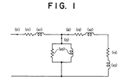
- Fig. 1 is an equivalent circuit diagram showing the organization of a conventional current transformer which is shown, for example, in K.Kamita, "Substation”, The Newest Advanced Experiment Lectures, Vol. 13, 3rd ed., April 30, 1977, Denki Shoin. In Fig.
- r1 represents the resistance portion of the primary side leakage impedance; x1, the reactance portion of the primary side leakage impedance; r2, the resistance portion (converted to the primary side equivalent) of the secondary side leakage impedance; x2, the reactance portion (converted to the primary side equivalent) of the secondary side leakage impedance; r3, the resitance portion (converted to the primary side equivalent) of the externally connected burden; x3, the reactance portion (converted to the primary side equivalent) of the externally connected burden; y0, the exciting admittance; i1, the primary current; i2, the secondary current; and i3, the exciting current.
- the current transformer continuously supplies an apparent power equal to: i2 ⁇ i2 ⁇ (r2 + r3 + j x2 + j x3) , wherein i2 is proportional to the primary current i1.
- the conventional transformer having an externally connected burden has the following disadvantages.
- the primary current i1 and hence the secondary current i2 proportional thereto is large, or when the secondary side leakgae impedance, r2 + j x2 , or the externally connected burden, r3 + j x3 , is large, the dimension of the core of the transformer should be large enough to avoid the saturation thereof.
- the current transformer comprises: a primary winding which forms part of the main circuit carrying the current to be measured; and secondary winding magnetically coupled to the primary winding; a burden coupled across the secondary winding; and a variable capacitor.
- r1 represents the resistance portion of the primary side leakage impedance
- x1 the reactance portion of the primary side leakage impedance
- r2 the resistance portion (converted to the primary side equivalent) of the secondary side leakage impedance
- x2 the reactance portion (converted to the primary side equivalent) of the secondary side leakage impedance
- r3 the resistance portion (converted to the primary side equivalent) of the externally connected burden
- x3 the reactance portion (converted to the primary side equivalent) of the externally connected burden
- y0 the exciting admittance; i1, the primary current; i2, the secondary current; and i3, the exciting current.
- a variable capacitor having an adjustable capacitance C0 is connected in series with the externally connected burden, r3 + j x3, and hence with the secondary side leakage impedance, r2 + j x2.
- the capacitance C0 of the capacitor is adjusted in such a manner that it is resonated serially with the reactance portion x2 (converted to the primary side equivalent) of the seconary side leakage impedance and the reactance portion x3 (converted to the primary side equivalent) of the externally connected burden.
- the capacitive reactance and the combined inductive reactance cancel each other, so that the overall reactance of the secondary side circuit substantially vanishes. Consequently, the core of the transformer can be reduced in size, and a small-sized and inexpensive current transformer is realized.
Landscapes
- Engineering & Computer Science (AREA)
- Power Engineering (AREA)
- Transformers For Measuring Instruments (AREA)
Applications Claiming Priority (2)
| Application Number | Priority Date | Filing Date | Title |
|---|---|---|---|
| JP102990/90 | 1990-04-20 | ||
| JP2102990A JPH043404A (ja) | 1990-04-20 | 1990-04-20 | 変流器 |
Publications (1)
| Publication Number | Publication Date |
|---|---|
| EP0453637A1 true EP0453637A1 (de) | 1991-10-30 |
Family
ID=14342142
Family Applications (1)
| Application Number | Title | Priority Date | Filing Date |
|---|---|---|---|
| EP90122325A Withdrawn EP0453637A1 (de) | 1990-04-20 | 1990-11-22 | Stromwandler |
Country Status (2)
| Country | Link |
|---|---|
| EP (1) | EP0453637A1 (de) |
| JP (1) | JPH043404A (de) |
Cited By (1)
| Publication number | Priority date | Publication date | Assignee | Title |
|---|---|---|---|---|
| CN111487486A (zh) * | 2020-03-06 | 2020-08-04 | 深圳供电局有限公司 | 配电变压器在线监测方法、装置、计算机设备及存储介质 |
Citations (3)
| Publication number | Priority date | Publication date | Assignee | Title |
|---|---|---|---|---|
| DE422920C (de) * | 1924-11-02 | 1925-12-15 | Siemens & Halske Akt Ges | Verfahren und Einrichtung zur Pruefung von Stromwandlern, beispielsweise nach der Methode Schering und Alberti |
| DE752154C (de) * | 1938-04-05 | 1953-04-27 | Aeg | Stabkernstromwandler |
| CH350710A (de) * | 1956-11-09 | 1960-12-15 | Bbc Brown Boveri & Cie | Stromwandleranlage für Höchstspannungsanlagen |
-
1990
- 1990-04-20 JP JP2102990A patent/JPH043404A/ja active Pending
- 1990-11-22 EP EP90122325A patent/EP0453637A1/de not_active Withdrawn
Patent Citations (3)
| Publication number | Priority date | Publication date | Assignee | Title |
|---|---|---|---|---|
| DE422920C (de) * | 1924-11-02 | 1925-12-15 | Siemens & Halske Akt Ges | Verfahren und Einrichtung zur Pruefung von Stromwandlern, beispielsweise nach der Methode Schering und Alberti |
| DE752154C (de) * | 1938-04-05 | 1953-04-27 | Aeg | Stabkernstromwandler |
| CH350710A (de) * | 1956-11-09 | 1960-12-15 | Bbc Brown Boveri & Cie | Stromwandleranlage für Höchstspannungsanlagen |
Cited By (2)
| Publication number | Priority date | Publication date | Assignee | Title |
|---|---|---|---|---|
| CN111487486A (zh) * | 2020-03-06 | 2020-08-04 | 深圳供电局有限公司 | 配电变压器在线监测方法、装置、计算机设备及存储介质 |
| CN111487486B (zh) * | 2020-03-06 | 2021-07-16 | 深圳供电局有限公司 | 配电变压器在线监测方法、装置、计算机设备及存储介质 |
Also Published As
| Publication number | Publication date |
|---|---|
| JPH043404A (ja) | 1992-01-08 |
Similar Documents
| Publication | Publication Date | Title |
|---|---|---|
| MX9605079A (es) | Sistema de control de celda optica. | |
| JPS54128653A (en) | Antenna unit for receiver | |
| KR950016341A (ko) | Catv용 신호 스플리터 회로 | |
| GB2017434A (en) | Earth leakage protection | |
| EP0185887A3 (de) | Verfahren und Schaltung zur Bestimmung von Entschlüssen in einem spulenförmigen Leiter | |
| DE3768736D1 (de) | Schaltungsanordnung fuer leistungsgrosstransformatoren. | |
| DE3371014D1 (en) | Earth leakage circuit breaker | |
| FR2430680A1 (fr) | Detecteur de courant de defaut continu ou alternatif | |
| ES8106077A1 (es) | Perfeccionamientos en dispositivos de ajuste y regulacion e lectronica para motores universales. | |
| GB2233523A (en) | Rectifier smoothing filter | |
| JPS55149593A (en) | Transmitting and receiving unit of ultrasonic wave | |
| GB939451A (en) | Improvements in or relating to a deflection transformer in, or for, a television receiver | |
| US3240957A (en) | Capacitor potential device | |
| ES8309051A1 (es) | Un transformador de salida horizontal para receptores de television. | |
| ATE109304T1 (de) | Impedanzanordnung zur begrenzung von transienten vorgängen. | |
| US2197937A (en) | Noise reduction system | |
| GB548301A (en) | Signal collecting systems for radio receivers and the like | |
| JPH043404A (ja) | 変流器 | |
| GB932864A (en) | Improvements in capacitor voltage transformers | |
| GB1476739A (en) | Frequency stop band electric filter | |
| SU955330A1 (ru) | Устройство дл защиты генератора от однофазных замыканий | |
| GB1597665A (en) | Voltage regulating transformer | |
| JPS5715502A (en) | Ferrite antenna device | |
| GB1217006A (en) | Electric inductance devices | |
| GB1478149A (de) |
Legal Events
| Date | Code | Title | Description |
|---|---|---|---|
| PUAI | Public reference made under article 153(3) epc to a published international application that has entered the european phase |
Free format text: ORIGINAL CODE: 0009012 |
|
| 17P | Request for examination filed |
Effective date: 19901220 |
|
| AK | Designated contracting states |
Kind code of ref document: A1 Designated state(s): CH DE FR LI SE |
|
| 17Q | First examination report despatched |
Effective date: 19931020 |
|
| STAA | Information on the status of an ep patent application or granted ep patent |
Free format text: STATUS: THE APPLICATION IS DEEMED TO BE WITHDRAWN |
|
| 18D | Application deemed to be withdrawn |
Effective date: 19940302 |