EP0453667B1 - Spritzenkonstruktion - Google Patents
Spritzenkonstruktion Download PDFInfo
- Publication number
- EP0453667B1 EP0453667B1 EP90304352A EP90304352A EP0453667B1 EP 0453667 B1 EP0453667 B1 EP 0453667B1 EP 90304352 A EP90304352 A EP 90304352A EP 90304352 A EP90304352 A EP 90304352A EP 0453667 B1 EP0453667 B1 EP 0453667B1
- Authority
- EP
- European Patent Office
- Prior art keywords
- chamber
- tube
- free piston
- contents
- resilient material
- Prior art date
- Legal status (The legal status is an assumption and is not a legal conclusion. Google has not performed a legal analysis and makes no representation as to the accuracy of the status listed.)
- Expired - Lifetime
Links
Images
Classifications
-
- A—HUMAN NECESSITIES
- A61—MEDICAL OR VETERINARY SCIENCE; HYGIENE
- A61M—DEVICES FOR INTRODUCING MEDIA INTO, OR ONTO, THE BODY; DEVICES FOR TRANSDUCING BODY MEDIA OR FOR TAKING MEDIA FROM THE BODY; DEVICES FOR PRODUCING OR ENDING SLEEP OR STUPOR
- A61M5/00—Devices for bringing media into the body in a subcutaneous, intra-vascular or intramuscular way; Accessories therefor, e.g. filling or cleaning devices, arm rests
- A61M5/178—Syringes
- A61M5/31—Details
- A61M5/315—Pistons; Piston-rods; Guiding, blocking or restricting the movement of the rod or piston; Appliances on the rod for facilitating dosing ; Dosing mechanisms
- A61M5/31596—Pistons; Piston-rods; Guiding, blocking or restricting the movement of the rod or piston; Appliances on the rod for facilitating dosing ; Dosing mechanisms comprising means for injection of two or more media, e.g. by mixing
-
- A—HUMAN NECESSITIES
- A61—MEDICAL OR VETERINARY SCIENCE; HYGIENE
- A61M—DEVICES FOR INTRODUCING MEDIA INTO, OR ONTO, THE BODY; DEVICES FOR TRANSDUCING BODY MEDIA OR FOR TAKING MEDIA FROM THE BODY; DEVICES FOR PRODUCING OR ENDING SLEEP OR STUPOR
- A61M5/00—Devices for bringing media into the body in a subcutaneous, intra-vascular or intramuscular way; Accessories therefor, e.g. filling or cleaning devices, arm rests
- A61M5/178—Syringes
- A61M5/28—Syringe ampoules or carpules, i.e. ampoules or carpules provided with a needle
- A61M5/284—Syringe ampoules or carpules, i.e. ampoules or carpules provided with a needle comprising means for injection of two or more media, e.g. by mixing
-
- A—HUMAN NECESSITIES
- A61—MEDICAL OR VETERINARY SCIENCE; HYGIENE
- A61M—DEVICES FOR INTRODUCING MEDIA INTO, OR ONTO, THE BODY; DEVICES FOR TRANSDUCING BODY MEDIA OR FOR TAKING MEDIA FROM THE BODY; DEVICES FOR PRODUCING OR ENDING SLEEP OR STUPOR
- A61M5/00—Devices for bringing media into the body in a subcutaneous, intra-vascular or intramuscular way; Accessories therefor, e.g. filling or cleaning devices, arm rests
- A61M5/178—Syringes
- A61M2005/1787—Syringes for sequential delivery of fluids, e.g. first medicament and then flushing liquid
-
- A—HUMAN NECESSITIES
- A61—MEDICAL OR VETERINARY SCIENCE; HYGIENE
- A61M—DEVICES FOR INTRODUCING MEDIA INTO, OR ONTO, THE BODY; DEVICES FOR TRANSDUCING BODY MEDIA OR FOR TAKING MEDIA FROM THE BODY; DEVICES FOR PRODUCING OR ENDING SLEEP OR STUPOR
- A61M5/00—Devices for bringing media into the body in a subcutaneous, intra-vascular or intramuscular way; Accessories therefor, e.g. filling or cleaning devices, arm rests
- A61M5/178—Syringes
- A61M5/31—Details
- A61M2005/3103—Leak prevention means for distal end of syringes, i.e. syringe end for mounting a needle
-
- A—HUMAN NECESSITIES
- A61—MEDICAL OR VETERINARY SCIENCE; HYGIENE
- A61M—DEVICES FOR INTRODUCING MEDIA INTO, OR ONTO, THE BODY; DEVICES FOR TRANSDUCING BODY MEDIA OR FOR TAKING MEDIA FROM THE BODY; DEVICES FOR PRODUCING OR ENDING SLEEP OR STUPOR
- A61M5/00—Devices for bringing media into the body in a subcutaneous, intra-vascular or intramuscular way; Accessories therefor, e.g. filling or cleaning devices, arm rests
- A61M5/178—Syringes
- A61M5/31—Details
- A61M2005/3128—Incorporating one-way valves, e.g. pressure-relief or non-return valves
-
- A—HUMAN NECESSITIES
- A61—MEDICAL OR VETERINARY SCIENCE; HYGIENE
- A61M—DEVICES FOR INTRODUCING MEDIA INTO, OR ONTO, THE BODY; DEVICES FOR TRANSDUCING BODY MEDIA OR FOR TAKING MEDIA FROM THE BODY; DEVICES FOR PRODUCING OR ENDING SLEEP OR STUPOR
- A61M5/00—Devices for bringing media into the body in a subcutaneous, intra-vascular or intramuscular way; Accessories therefor, e.g. filling or cleaning devices, arm rests
- A61M5/178—Syringes
- A61M5/28—Syringe ampoules or carpules, i.e. ampoules or carpules provided with a needle
- A61M5/285—Syringe ampoules or carpules, i.e. ampoules or carpules provided with a needle with sealing means to be broken or opened
- A61M5/286—Syringe ampoules or carpules, i.e. ampoules or carpules provided with a needle with sealing means to be broken or opened upon internal pressure increase, e.g. pierced or burst
Definitions
- This invention relates to a syringe construction.
- hypodermic needles As it is well known, the spread of infection by hypodermic needles is a serious problem, especially as one using a hypodermic injector is very likely to touch the needle and be infected by contact. It is also noted that the sequential injection of contents while maintaining the contents separate is a problem not heretofore satisfactorily overcome. It is also noted that prior art syringes with sealed off compartments within the syringe require advance manipulation before they can be used.
- a hypodermic injector wherein contents in one or more separate chambers may be reliably injected sequentially from the separate chambers.
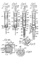
- Figure 1 is a longitudinal sectional view of a single chamber hypodermic ready for use.
- Figure 2 is a longitudinal sectional view of a single chamber hypodermic with the contents stored in an intermediate position in the syringe tube.
- Figure 3 is a longitudinal sectional view of a two-chamber hypodermic ready for use taken along line 3-3 of Figure 10.
- Figure 4 is a longitudinal sectional view of a three-chamber hypodermic ready for use.
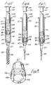
- Figure 5 is a longitudinal sectional view of a two-chamber hypodermic using a different configuration of chambers.
- Figure 6 is a view similar to Figure 5 with the contents of the first chamber discharged.
- Figure 7 is a view similar to Figure 6 showing the contents of the second chamber flowing past the free piston.
- Figure 8 is a perspective of one type of free piston.
- Figure 9 is a perspective of a second type of free piston.
- Figure 10 is a cross section of the second type of free piston.
- Figure 11 is a cross section generally along line 11-11 of Figure 10.
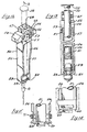
- Figure 12 is a perspective of a holder for holding the syringe if the syringe is made without a finger flare.
- Figure 13 is a cross section generally along line 13-13 of Figure 12.
- Figure 14 is a partial view of the holder of Figure 13 showing the holder in open and closed position.
- Figure 15 is a partial view similar to Figure 14 with a separate clip member for transferring the holder from its open position to its closed position.
- a hypodermic needle or syringe generally designated 20 and including a generally cylindrical tube or cartridge 21, ordinarily of glass or plastic.
- the tube 21 has an open end 28, the upper end in Figures 1-7, open as by an out-turned lip or flange 22.
- the other, lower end of the cylindrical tube 21 is reduced, as by an end wall or shoulder 23 to a reduced outlet port 24.
- the interior of the reducing end wall 23 may provide an annular internal shoulder, as at 25.
- Extending from the reduced outlet port 24 may be an injection needle 26 communicating with the interior of the tube 21 through a connector 27 or secured to the inside of outlet port 24.
- a piston 31 On a rod 30 extending into the open end 28 of the tube or cylinder 21 is a piston 31 in snug sliding engagement with the interior of the tube.
- the piston or enlarged head 31 on the rod 30 may be of rubber or other suitable sealing material, and the rod 30 may be provided on its outer end, exteriorly of the tube 21 with a head 32.
- the free piston 33 may be of a flexible rubber-like material and has an end of a hollow shape configuration 48 facing toward the end wall 23.
- This end with a hollow shape 48 may be circular in shape as shown in Figures 5, 6 and 7 or it may be flat and narrow in shape as shown in Figures 9, 10 and 11. It may also be filled with a low strength compressible material.
- the free piston 33 includes a closed end 34 of less external diameter than the interior of the tube 21.
- the oblique side wall 35 terminates at its larger end in a generally cylindrical peripheral sealing surface 36 in slidable conforming engagement with the interior of the cylindrical wall of tube 21.
- the larger end of the side wall 35 of free piston 33 is generally cylindrical to form the sealing surface 36, for sealing engagement with the interior of tube 21.
- this sealing surface 36 may be two or more surfaces.
- the free piston side wall 35 may have external ribs 37 extending generally from the sealing surface 36 to the closed end 34 of the free piston 33. These ribs help to prevent tipping of the piston as it moves in the tube 21.
- the free piston 33 is generally hollow, with a generally flat closed end 34, and a flaring side wall 35 terminating in at least one sealing surface 36.
- the end with the hollow shape 48 is provided with a plurality of lugs 40 as shown in Figure 4 or a stopper movement inhibitor surface 40A as shown in Figures 9 and 10.
- a path 39 for the contents of the syringe to flow through is generated by the lugs 40 or by the opening in the stopper movement inhibitor surface 40A.
- the annular array of lugs 40 or the stopper movement inhibitor surface 40A is engageable with the internal shoulder 25, resulting in the condition shown in Figures 1, 6 and 10.
- the free piston 33 can be located in the syringe 20 in different positions to allow different uses of the syringe.
- Figure 1 shows the free piston 33 located adjacent to internal shoulder 25. In this position, the syringe has only one contents chamber 41.
- Figure 2 also shows a syringe with one contents chamber 41 with the contents stored in the tube 20 still sealed by the inner wall of the tube 21, the piston 31 and the free piston 33.
- two free pistons 33 are used in the syringe 20.
- the lower free piston 33 located adjacent the internal shoulder 25, the intermediate piston 33A, and the inner wall of tube 21, form the first contents chamber.
- the intermediate piston 33A, piston 31, and the inner wall of tube 21 form the second contents chamber.
- the lower or first contents chamber is composed of the free piston 33, a needle seal 45, and the inner wall of tube 21.
- the second chamber comprises two free pistons 33 and 33A
- the third chamber comprises a free piston 33A and piston 31. It is possible to add additional chambers therefore merely by adding additional free pistons 33. If a free piston were used as shown in Figure 1 adjacent surface 25 in the syringe shown in Figure 4, the lower chamber would be formed of two free pistons 33 and the inner wall of tube 21. In this arrangement, the needle seal 45 would not be needed.
- Figure 5 shows a two-chamber syringe in which a needle seal 45 forms a part of the lower chamber.
- a free piston 33 can be used to provide a syringe with one, two, three or more contents chambers.
- the needle seal 45 In order to discharge the contents from the syringe, the needle seal 45 must be removed from the syringe filled with contents as shown in Figures 4 and 5. If the syringes are filled as shown in Figures 1, 2 or 3, it would only be necessary to remove a cover 45A similar to that shown in Figure 2 if the syringe is a sterile application. If the syringe is not a sterile type application, no cover would be needed on the syringe outlet port, since the contents are sealed inside the syringe.
- a needle cover 45A which helps prevent this accidental puncture is shown in Figure 2.
- the contents to be injected is contained in the chamber inside the syringe.
- the needle cover 45A does not have to seal the syringe, but has to keep the needle clean and sterile. This can be accomplished by a cover which employs the principle of "tortuous path.” That is, there cannot be a straight path to the item to remain sterilized.
- tube 21 is provided with a lip 42 with a locking corner 43.
- the cover 45A is provided with a mating locking corner 44 as well as a tapered assembly surface 46.
- the cover 45A In storage, or prior to use, the cover 45A is assembled to the tube 21 with the tapered assembly surface 46 engaging the lip 42, thus retaining it in position. In using the syringe, the administrator removes the cover 45A by sliding it off the lip 42.
- the cover 45A is designed to have enough yield at this point to allow for circumferential stretch. After the needle is used, the needle can be very contagious. As a result, the cover 45A or seal 45 must be replaced.
- the target area to reinsert the needle 26 is much larger in Figure 2 than in Figures 4 and 5. Since the seal shown in Figures 4 and 5 also must be sealable against the needle 26, the material normally used for this function is a rubber or rubber-like material. It is possible for the needle even though it has entered the target hole to pierce the material of the seal and puncture the administrator.
- the cover 45A shown in Figure 2 can be made of a solid plastic material which cannot be punctured by the needle.
- the cover is reinserted onto tube 21 a greater distance than from which it was removed. Moving this further distance engages a locking corner 44 of the cover with locking corner 43 of the tube 21, thus locking the cover to the tube.
- An additional flange or shield 47 can be added to cover 45A for further protection as well as aid in reassembly of the cover.
- the free piston 33 is provided with means for the contents to bypass the free piston when the free piston 33 has engaged internal shoulder 25.
- a first contents is introduced into a first chamber 41 within the tube 21 located between the tube end 23 and the free piston 33.
- a second contents is contained in the second chamber 41A defined by the space between the free piston 33 and the piston 31.
- Movement of piston 31 into the tube 21 displaces the contents of chamber 41 out of the tube and moves the free piston 33A to a position with the lugs 40 or movement inhibitor surface 40A just engaging the internal shoulder 25 of the tube end wall 23.
- a content to be injected is introduced as at 41. Movement of piston 31 inwardly into the tube seats the movement inhibitor surface 40A of the free piston 33 adjacent the surface 25 of tube end 23. Further inward movement of piston 31 causes the flow of the contents past the free piston 33 similarly described above.
- FIGS 12-15 illustrate a holder constructed in accordance with the instant invention.
- a holder generally designated 50 as in Figures 12 and 13, holds a hypodermic syringe cartridge 51.
- the hypodermic syringe cartridge 51 is basically the same as the syringe 20 shown in Figures 1-7 except that the flange 22 is eliminated.
- the hypodermic syringe cartridge 51 is shown in longitudinal section in Figure 13, and in phantom in Figure 12.
- the holder 50 may be molded of plastic, or otherwise suitably formed, and includes a transversely enlarged upper end portion or head 52 having a central opening 53 from which extend laterally outwardly a pair of finger holds 54.
- a pair of opposed side members 56 which extend in the downward direction away from the enlarged head 52.
- a pair of cross-pieces or transverse members 57 extends between the elongated side members 56 in the region adjacent to the head 52.
- the elongated members 56 are free to swing toward and away from each other from the cross-pieces 57 to their free ends 58.
- a snap hook 59 is provided adjacent to one end of one elongated side member 56 for a selective holding engagement with the other side member 56. Upon opening of the snap hook 59, the elongated side members 56 spread apart for receiving therebetween the tube 51 of an injection device.
- the tube 51 of the injection device has its outlet end wall 23 in bearing engagement with inturned flanges 60, Figures 13 and 14 on the free ends 58 of elongated side members 56. That is, the inturned flanges 60 on the ends of the elongated side members 56 serve to retain the tube 51 in position within the carrier or holder 50.
- a pair of resilient fingers 62 extend inwardly from opposite finger holds 54 into central opening 53, there terminating short of each other for resilient bearing engagement of the members with the end of tube 51 to position the latter longitudinally in the holder 50.
- the tube 51 is held longitudinally between the inturned flanges 60 and the resilient fingers 62, while the tube is held laterally with its upper region engaging cross-pieces 57 and its lower region held by the elongated side members 56 removably secured by the snap hook 59.
- the lower ends of elongated side members 56 of holder 50 are releasably retained snugly against the tube 51, with the inturned ends 60 engaging about the end 23 of the tube 51.
- the snap hook 59 may be opened to release the elongated side members 56, as illustrated in Figure 14 for movement away from the tube 51, whereby the tube is released for outward swinging movement beyond inturned flanges 60 and dropped from the holder 50.
- a guide member 67 on the upper end of head 52 is provided with a hole 68 for guiding and retaining rod 30.
- an injector without the flange 22 may be carried by a holder 50 in the manner described above, and a rod 30 with a head 32 applied thereto.
- Figure 15 illustrates a slightly modified embodiment wherein elongated side members 56 have a portion of the leg adjacent the inturned flanges 60 modified to retain a clip 71 slideable to shift the inturned flanges 60 to the holding position with respect to the tube 51 as shown by the solid lines.
- the present invention provides a syringe for hypodermic injection of contents from a single closed chamber by several methods, of sequential contents from separate closed chambers and a holder for the injection device, if desired, all of which are extremely simple in construction and accomplish their intended objects without departing from the present invention as defined in the appended claims.
Landscapes
- Health & Medical Sciences (AREA)
- Vascular Medicine (AREA)
- Engineering & Computer Science (AREA)
- Anesthesiology (AREA)
- Biomedical Technology (AREA)
- Heart & Thoracic Surgery (AREA)
- Hematology (AREA)
- Life Sciences & Earth Sciences (AREA)
- Animal Behavior & Ethology (AREA)
- General Health & Medical Sciences (AREA)
- Public Health (AREA)
- Veterinary Medicine (AREA)
- Infusion, Injection, And Reservoir Apparatuses (AREA)
Claims (23)
- Spritzenaufbau (20), umfassend ein zylindrisches Rohr (21), eine Auslaßöffnung (24) an einem Ende des genannten Rohrs (21), einen Druckkolben (31), der aus einem elastischen Material hergestellt ist und sich vom anderen Ende des genannten Rohrs (21) nach innen erstreckt, einen aus einem elastischen Material hergestellten freien Kolben (33), der in dem genannten Rohr (21) zwischen dem genannten Druckkolben (31) und der genannten Auslaßöffnung (24) angeordnet ist, wobei der genannte Druckkolben (31), der genannte freie Kolben (33) und das genannte zylindrische Rohr (21) eine Kammer (41), (41A), (41B) bilden, die fähig ist, einen Inhalt zu enthalten, eine äußere Dichtungsfläche (36), (36A) auf einem ersten Ende des genannten freien Kolbens (33), das nahe der genannten Auslaßöffnung (24) angeordnet ist, ein schmaleres zweites Ende (34) des genannten freien Kolbens (33), das nahe dem genannten Druckkolben (31) angeordnet ist, wobei der freie Kolben (33) eine konisch zulaufende Oberfläche zwischen der genannten Dichtungsfläche (36), (36A) und dem genannten schmaleren zweiten Ende (34) und einen Hohlraum (48) aufweist, der sich in dem genannten freien Kolben (33) von dem genannten ersten Ende über eine Höhe erstreckt, die größer als die Länge in Längsrichtung der genannten äußeren Dichtungsfläche (36), (36A) des genannten freien Kolbens (33) ist, wobei der genannte freie Kolben (33) eine einknickbare Wand (35) zwischen der genannten konisch zulaufenden Oberfläche und dem genannten Hohlraum (48) besitzt, wobei die Wand (35) in den genannten Hohlraum (48) einknickbar ist, wenn der Druck auf der genannten konisch zulaufenden Oberfläche den Druck der genannten Dichtungsfläche (36), (36A) gegen das genannte zylindrische Rohr (21) übersteigt.
- Spritzenaufbau (20) nach Anspruch 1, der einen zwischen dem genannten ersten freien Kolben (33) und dem genannten Druckkolben (31) angeordneten zweiten freien Kolben (33A) in dem genannten Rohr (21) umfaßt, der die genannte Kammer in einen ersten Abschnitt (41) und einen zweiten Abschnitt (41A) unterteilt, wobei jeder der genannten Abschnitte fähig ist, einen Inhalt zu enthalten.
- Spritzenaufbau (20) nach Anspruch 1, der eine Dichtungseinrichtung (45) auf der genannten Auslaßöffnung (24) umfaßt, wobei der freie Kolben (33) und die genannte Dichtungseinrichtung (45) eine zweite Kammer (41) bilden, wobei die genannte zweite Kammer (41) fähig ist, einen Inhalt zu enthalten.
- Spritzenaufbau (20) nach Anspruch 1, der ein zusammendrückbares Material in dem genannten Hohlraum (48) umfaßt, wobei das zusammendrückbare Material fähig ist, sich durch eine Bewegung der genannten einknickbaren Wand (35) zusammendrücken zu lassen.
- Spritzenaufbau (20) nach Anspruch 3, dadurch gekennzeichnet, daß ein Druck auf einen Inhalt in der genannten zweiten Kammer (41) eine Erhöhung des Drucks der genannten äußeren Dichtungsfläche (36), (36A) des genannten freien Kolbens gegen das genannte zylindrische Rohr (21) bewirkt.
- Spritzenaufbau (20) nach Anspruch 1, der eine an der genann- ten Auslaßöffnung (24) angebrachte Hohlnadel (26) umfaßt.
- Spritzenaufbau (20) nach Anspruch 6, der eine Dichtungseinrichtung (45) auf der genannten Nadel (26) umfaßt, wobei der genannte freie Kolben (33), die genannte Dichtungseinrichtung (45) auf der genannten Nadel (26) und der genannte Zylinder (21) eine zweite Kammer (41) bilden, wobei die genannte zweite Kammer (41) fähig ist, einen Inhalt zu enthalten.
- Spritzenaufbau (20) nach Anspruch 6, der eine Ecke (43) auf dem genannten zylindrischen Rohr (21) nahe der genannten Auslaßöffnung (24), eine Abdeckung (45A) für die genannte Nadel (26), eine konisch zulaufende Oberfläche auf der Innenseite der genannten Abdeckung (45A), eine Verschlußecke (44) auf der Innenseite der genannten Abdeckung (45A) umfaßt, wobei für eine Lagerung die Ecke (43) auf dem genannten zylindrischen Rohr (21) in die genannte konisch zulaufende Oberfläche eingreift und die genannte Ecke (43) des genannten zylindrischen Rohrs (21) nach dem Entfernen und Wiederanbringen der genannten Abdeckung an dem genannten zylindrischen Rohr (21) in die genannte Verschlußecke (44) auf der Innenseite der genannten Abdeckung (45A) eingreift.
- Spritzenaufbau (20) nach Anspruch 1, der eine Vielzahl zwischen dem genannten freien Kolben (33) und dem genannten Druckkolben (31) angeordneter freier Kolben umfaßt, die die genannte Kammer in eine Vielzahl von Kammern (41), (41A), (41B) unterteilt, wobei jede Kammer fähig ist, einen Inhalt zu enthalten.
- Spritzenaufbau (20) nach Anspruch 1, der eine Stabilisierungsfläche (37) auf dem genannten freien Kolben (33) umfaßt, wobei die genannte Stabilisierungsfläche (37) mit dem genannten zylindrischen Rohr (21) zusammenwirkt, um die Ausrichtung des genannten freien Kolbens (33) in dem genannten zylindrischen Rohr (21) beizubehalten.
- Spritzenaufbau (20) nach Anspruch 1, dadurch gekennzeichnet, daß auf der Außenseite des genannten freien Kolbens (33) zum führenden Eingriff mit dem genannten Rohr (21) Führungsrippen (37) ausgebildet sind, um die Ausrichtung zwischen dem genannten freien Kolben (33) und dem genannten Rohr (21) beizubehalten.
- Spritzenaufbau (20) nach Anspruch 1 in Kombination mit einem Halter (50), gekennzeichnet durch ein Kopfteil (52) in tragendem Eingriff mit dem anderen Ende des genannten Rohrs (21), ein Paar Seitenelemente (56), die sich von dem genannten Kopfteil (52) auf entgegengesetzten Seiten des genannten Rohrs (21) erstrecken und elastisch zueinander und zu dem genannten Rohr (21) und davon wegbiegbar sind, und durch dazwischenpassende Anordnungen (59) auf den genannten Seitenelementen (56), die die genannten Seitenelemente (56) lösbar zueinander halten, um das genannte Rohr (21) in dem genannten Halter (50) lösbar zu halten.
- Spritzenaufbau (20) nach Anspruch 12, dadurch gekennzeichnet, daß auf den genannten Seitenelementen (56) Halter (60) angeordnet sind, um das genannte Rohr (21) in dem genannten Halter (50) zurückzuhalten, wenn die genannten Seitenelemente (56) zueinander stehen, wobei die genannten Halter (60) beim Spreizen der Seitenelemente (56) mit Abstand voneinander angeordnet sind, um das genannte Rohr (21) von dem genannten Halter (50) zu lösen.
- Spritzenaufbau (20) nach Anspruch 12, bei dem das genannte Kopfteil (52) des Halters durch wenigstens einen Federfinger (62) in tragendem Eingriff mit dem genannten anderen Rohrende gekennzeichnet ist, um das Rohr (21) in seiner Position zu einem Halter (60) zu halten, wobei sich der genannte Federfinger (62) quer von dem genannten Halter (50) erstreckt, um sich bei Eingriff mit dem genannten anderen Rohrende elastisch durchzubiegen.
- Kammer (41), umfassend einen Druckabschnitt (31), ein Abgabeende (24), einen Stopfen (33) aus elastischem Material, der nahe dem genannten Abgabeende (24) angeordnet ist, Mittel (25), (40), (40A), um die Bewegung des genannten Stopfens (33) aus elastischem Material zu beschränken, ein erstes Ende und ein zweites Ende (34) auf dem genannten Stopfen (33) aus elastischem Material, wobei das genannte erste Ende zum genannten Abgabeende (24) der genannten Kammer (41) zeigt und das genannte zweite Ende (34) zum genannten Druckabschnitt (31) der genannten Kammer (41) zeigt, eine ringförmige Dichtungsfläche (36), (36A) nahe dem genannten ersten Ende des genannten Stopfens (33), eine konisch zulaufende Wand (35), die sich von der genannten ringförmigen Dichtungsfläche (36) zu dem genannten zweiten Ende (34) des genannten Stopfens (33) hin erstreckt, wobei das genannte zweite Ende (34) schmaler als das genannte erste Ende ist, einen Hohlraum (48) in dem genannten Stopfen (33), der sich von dem genannten ersten Ende nach innen zu dem genannten zweiten Ende (34) hin erstreckt, wobei die genannte konisch zulaufende Wand (35) durch von dem genannten Druckabschnitt (31) auf die genannte konisch zulaufende Wand (35) angewendeten Druck nach innen in den genannten Hohlraum (48) einknickbar ist, wenn der genannte Stopfen (33) aus elastischem Material durch die genannten Mittel (25), (40), (40A) zum Beschränken der Bewegung an einer Bewegung gehindert wird.
- Kammer (41) nach Anspruch 15, die einen zweiten Stopfen (33A) aus elastischem Material umfaßt, der zwischen dem genannten ersten Stopfen (33) aus elastischem Material und dem genannten Druckabschnitt (31) angeordnet ist, wodurch die genannte Kammer eine erste Kammer (41) für einen Inhalt zwischen den genannten ersten und zweiten Stopfen (33), (33A) aus elastischem Material, eine zweite Kammer (41A) für einen Inhalt zwischen dem genannten zweiten Stopfen (33A) aus elastischem Material und dem genannten Druckabschnitt (31) bildet, wobei der genannte erste Stopfen (33) durch Druck vom Inhalt in der genannten ersten Kammer (41) einknickbar ist und der genannte zweite Stopfen (33A) von Druck vom Inhalt in der genannten zweiten Kammer (41A) einknickbar ist, wenn der genannte zweite Stopfen (33A) aus elastischem Material durch den genannten ersten Stopfen (33) aus elastischem Material an einer Bewegung gehindert wird.
- Kammer (41) nach Anspruch 15, die eine Dichtungseinrichtung (45) für das genannte Abgabeende (24) umfaßt, wobei die genannte Kammer gekennzeichnet ist durch eine erste Kammer (41) für einen Inhalt zwischen der genannten Dichtungseinrichtung (45) für das genannte Abgabeende (24) und dem genannten ersten Ende des genannten Stopfens (33) aus elastischem Material und durch eine zweite Kammer (41A) für einen Inhalt zwischen dem genannten zweiten Ende (34) des genannten Stopfens (33) aus elastischem Material und dem genannten Druckabschnitt 31.
- Kammer (41) nach Anspruch 15, die eine Vielzahl von Stopfen (33), (33A) aus elastischem Material umfaßt, wobei die Kammer (41) eine Vielzahl von Abschnitten (41), (41A), (41B) umfaßt, wobei sich jeder Abschnitt zwischen einem genannten zweiten Ende eines Stopfens und einem benachbarten ersten Ende eines benachbarten Stopfens befindet.
- Kammer (41) nach Anspruch 15, die eine Dichtungseinrichtung (45) für das genannte Abgabeende (24) und eine Vielzahl von Stopfen aus elastischem Material einschließt, wobei die Kammer (41) gekennzeichnet ist durch eine Vielzahl aufeinanderfolgender Abschnitte (41), (41A), (41B), wobei die genannte Dichtung (45) und das genannte erste Ende des ersten der genannten Stopfen den genannten ersten Abschnitt bilden und das genannte zweite Ende der genannten Stopfen und das genannte erste Ende der genannten aufeinanderfolgenden Stopfen die genannten aufeinanderfolgenden Abschnitte bilden.
- Bewegliches Trennstück (33) aus elastischem Material für jeden Abschnitt einer aus mehreren Abschnitten bestehenden, unter Druck setzbaren Kammer (41), (41A) mit einem ersten Ende auf dem genannten Trennstück (33), (33A), einer ringförmigen Oberfläche (36), (36A), die relativ zum genannten ersten Ende des genannten Trennstücks (33), (33A) zur Abdichtung zwischen dem genannten Trennstück (33), (33A) und jedem jeweiligen Abschnitt der genannten Kammer (41), (41A) angeordnet ist, einem zweiten Ende (34), (34A) des genannten Trennstücks (33), (33A), wobei das genannte zweite Ende (34), (34A) des genannten Trennstücks (33), (33A) von kleinerer entsprechender Abmessung als die genannte ringförmige Oberfläche (36), (36A) ist, einem Hohlraum (48), der sich von dem genannte ersten Ende in das genannte Trennstück (33), (33A) erstreckt, einer ersten einknickbaren Verbindungswand (35) zwischen der genannten ringförmigen Oberfläche (36), (36A) und dem unteren Ende des genannten Hohlraums (48), die eine Außenfläche und eine Innenfläche besitzt, wobei die einknickbare Verbindungswand (35) durch Druck von einer unter Druck setzbaren Einrichtung (31), die einen auf die genannte Außenfläche übertragbaren Druck schafft, wenn das genannte Trennstück (33), (33A) an einer Bewegung gehindert wird, in den genannten Hohlraum (48) einknickbar ist.
- Bewegliches Trennstück (33), (33A) aus elastischem Material nach Anspruch 20, das in dem genannten Hohlraum (48) ein zusammendrückbares Material umfaßt, wobei das zusammendrückbare Material durch das Einknicken der genannten einknickbaren Verbindungswand (35) zusammendrückbar ist.
- Bewegliches Trennstück (33), (33A) aus elastischem Material nach Anspruch 20, das Mittel umfaßt, um die Bewegung des Trennstücks zu beschränken, gekennzeichnet durch eine Anschlagfläche (40), (40A) nahe dem genannten ersten Ende des genannten Trennstücks (33), (33A), die an ein Bewegungsbeschränkungselement (25) in der genannten Kammer (41), (41A) anstößt, um die Bewegung des genannten Trennstücks (33), (33A) zu beschränken.
- Bewegliches Trennstück (33), (33A) aus elastischem Material nach Anspruch 22, dadurch gekennzeichnet, daß das genannte erste Ende des genannten Trennstücks (33), (33A) angepaßt ist, um ein entsprechendes zweites Ende eines vorangehenden Trennstücks zu berühren, um die Bewegung aufeinanderfolgender Trennstücke zu beschränken.
Priority Applications (2)
| Application Number | Priority Date | Filing Date | Title |
|---|---|---|---|
| DE1990609981 DE69009981T2 (de) | 1990-04-23 | 1990-04-23 | Spritzenkonstruktion. |
| AT90304352T ATE107179T1 (de) | 1990-04-23 | 1990-04-23 | Spritzenkonstruktion. |
Applications Claiming Priority (1)
| Application Number | Priority Date | Filing Date | Title |
|---|---|---|---|
| US07/252,792 US4929230A (en) | 1988-09-30 | 1988-09-30 | Syringe construction |
Publications (2)
| Publication Number | Publication Date |
|---|---|
| EP0453667A1 EP0453667A1 (de) | 1991-10-30 |
| EP0453667B1 true EP0453667B1 (de) | 1994-06-15 |
Family
ID=22957570
Family Applications (1)
| Application Number | Title | Priority Date | Filing Date |
|---|---|---|---|
| EP90304352A Expired - Lifetime EP0453667B1 (de) | 1988-09-30 | 1990-04-23 | Spritzenkonstruktion |
Country Status (2)
| Country | Link |
|---|---|
| US (1) | US4929230A (de) |
| EP (1) | EP0453667B1 (de) |
Families Citing this family (89)
| Publication number | Priority date | Publication date | Assignee | Title |
|---|---|---|---|---|
| US4929230A (en) * | 1988-09-30 | 1990-05-29 | Pfleger Frederick W | Syringe construction |
| US5104375A (en) * | 1989-10-16 | 1992-04-14 | Johnson & Johnson Medical, Inc. | Locking holder for a pair of syringes and method of use |
| US5092843A (en) * | 1990-04-12 | 1992-03-03 | Survival Technology, Inc. | Dispersion multichamber auto-injector |
| JP2586883B2 (ja) * | 1992-12-01 | 1997-03-05 | 哲郎 東川 | 注射器 |
| AU682670B2 (en) * | 1993-02-05 | 1997-10-16 | Becton Dickinson & Company | Syringe needle isolation device |
| US5743890A (en) * | 1993-02-17 | 1998-04-28 | Pharmacia & Upjohn Aktiebolag | Pistons for injection cartridges |
| SG46610A1 (en) * | 1993-12-28 | 1998-02-20 | Tetsuro Higashikawa | Syringe |
| US5549574A (en) * | 1994-08-30 | 1996-08-27 | Eli Lilly And Company | Cartridge assembly for use in a pen-type medicament injector |
| SK5097A3 (en) * | 1995-08-09 | 1997-10-08 | Tetsuro Higashikawa | Syringe, sealing construction and method therefor, and slide valve for syringe |
| AU754859B2 (en) * | 1995-08-09 | 2002-11-28 | Tetsuro Higashikawa | Sliding valve for syringe |
| DE29605790U1 (de) * | 1996-03-28 | 1996-08-08 | Dr. Karl Thomae Gmbh, 88400 Biberach | Spritze für medizinische Zwecke |
| US5865798A (en) | 1996-06-28 | 1999-02-02 | Becton Dickinson France, S.A. | Stopper assembly having bypass features for use in a multi-chamber syringe barrel |
| US5713857A (en) | 1996-06-28 | 1998-02-03 | Becton Dickinson France, S.A. | Sequential stopper |
| WO1998046136A1 (fr) | 1997-04-15 | 1998-10-22 | Debiotech S.A. | Seringue a compartiments multiples |
| SE9703226D0 (sv) * | 1997-09-08 | 1997-09-08 | Astra Ab | New pharmaceutical composition |
| US6027481A (en) * | 1999-03-08 | 2000-02-22 | Becton Dickinson And Company | Prefillable syringe |
| ATE308354T1 (de) | 1999-04-16 | 2005-11-15 | Becton Dickinson Co | Stiftförmiger injektor mit merkmalen zur automatischen substanzkombination |
| US6382204B1 (en) * | 1999-10-14 | 2002-05-07 | Becton Dickinson And Company | Drug delivery system including holder and drug container |
| USD447559S1 (en) | 1999-10-14 | 2001-09-04 | Becton, Dickinson And Company | Drug container holder |
| USD463546S1 (en) | 1999-10-14 | 2002-09-24 | Becton Dickinson And Company | Drug container holder |
| USD448474S1 (en) | 1999-10-14 | 2001-09-25 | Becton, Dickinson And Company | Drug container holder |
| USD446578S1 (en) | 1999-10-14 | 2001-08-14 | Becton, Dickinson And Company | Drug container holder |
| EP1092447B1 (de) * | 1999-10-14 | 2004-01-07 | Becton Dickinson and Company | Nasales Verabreichungsgerät mit Zerstäuberdüse |
| US6423050B1 (en) | 2000-06-16 | 2002-07-23 | Zbylut J. Twardowski | Method and apparatus for locking of central-vein catheters |
| FR2822710B1 (fr) * | 2001-03-27 | 2004-04-02 | Lab Contactologie Appl Lca | Seringue pour solutions viscoleastiques |
| US7021561B2 (en) | 2001-12-18 | 2006-04-04 | Becton, Dickinson And Company | Spray device and method |
| FR2842428B1 (fr) * | 2002-07-19 | 2004-10-08 | Becton Dickinson France | Dispositif d'injection d'un produit, notamment a usage medical |
| FR2845016B1 (fr) * | 2002-09-27 | 2004-12-03 | Becton Dickinson France | Dispositif de pulverisation ou d'injection permettant de delivrer au moins deux doses determinees de produit |
| GB0302536D0 (en) * | 2003-02-04 | 2003-03-12 | Bespak Plc | Container |
| US20040167480A1 (en) * | 2003-02-21 | 2004-08-26 | Advanced Medical Optics, Inc. | Administration of multiple viscoelastic solutions with a multi-compartment syringe |
| US7561916B2 (en) | 2005-06-24 | 2009-07-14 | Ethicon Endo-Surgery, Inc. | Implantable medical device with indicator |
| US8715243B2 (en) | 2003-06-16 | 2014-05-06 | Ethicon Endo-Surgery, Inc. | Injection port applier with downward force actuation |
| US7862546B2 (en) * | 2003-06-16 | 2011-01-04 | Ethicon Endo-Surgery, Inc. | Subcutaneous self attaching injection port with integral moveable retention members |
| US8029477B2 (en) * | 2003-12-19 | 2011-10-04 | Ethicon Endo-Surgery, Inc. | Applier with safety for implantable medical device |
| US8162897B2 (en) * | 2003-12-19 | 2012-04-24 | Ethicon Endo-Surgery, Inc. | Audible and tactile feedback |
| US7998106B2 (en) | 2004-05-03 | 2011-08-16 | Thorne Jr Gale H | Safety dispensing system for hazardous substances |
| US7101354B2 (en) * | 2004-05-03 | 2006-09-05 | Infusive Technologies, Llc | Mixing syringe with and without flush |
| US6997910B2 (en) * | 2004-05-03 | 2006-02-14 | Infusive Technologies, Llc | Multi-chamber, sequential dose dispensing syringe |
| SE0401569D0 (sv) * | 2004-06-17 | 2004-06-17 | Gambro Lundia Ab | Applikator |
| US20060178644A1 (en) * | 2004-12-03 | 2006-08-10 | Reynolds David L | Pharmaceutical cartridge assembly and method of filling same |
| JP4686202B2 (ja) * | 2005-02-02 | 2011-05-25 | 大成化工株式会社 | シリンジ |
| US8529517B2 (en) * | 2005-05-02 | 2013-09-10 | Shi Zi Technology, Ltd. | Autoflush syringe |
| US8936577B2 (en) | 2005-05-02 | 2015-01-20 | Shi Zi Technology, Ltd. | Methods and devices for autoflush syringes |
| US8075533B2 (en) | 2005-05-02 | 2011-12-13 | Preventiv, Inc. | Autoflush syringe |
| WO2006124819A1 (en) * | 2005-05-16 | 2006-11-23 | Mallinckrodt Inc. | Multi-stage syringe and methods of using the same |
| US7918844B2 (en) | 2005-06-24 | 2011-04-05 | Ethicon Endo-Surgery, Inc. | Applier for implantable medical device |
| US7651483B2 (en) * | 2005-06-24 | 2010-01-26 | Ethicon Endo-Surgery, Inc. | Injection port |
| DE102005038495A1 (de) * | 2005-08-13 | 2007-02-15 | Boehringer Ingelheim Pharma Gmbh & Co. Kg | Doppelkammer-Behälter und Verfahren zu dessen Befüllung |
| DE102005038368A1 (de) * | 2005-08-13 | 2007-02-15 | Boehringer Ingelheim Pharma Gmbh & Co. Kg | Doppelkammer-Behälter zur Lyophilisation, Verfahren zu dessen Befüllung und dessen Verwendung |
| US7547300B2 (en) | 2006-04-12 | 2009-06-16 | Icu Medical, Inc. | Vial adaptor for regulating pressure |
| JP2008259704A (ja) * | 2007-04-12 | 2008-10-30 | Hisamitsu Pharmaceut Co Inc | プレフィルド型シリンジ |
| US7789862B2 (en) * | 2007-09-05 | 2010-09-07 | Thorne Consulting & Intellectual Property, LLC | Multi-chamber, sequentially dispensing syringe |
| CA2639729A1 (en) * | 2007-09-27 | 2009-03-27 | Tyco Healthcare Group Lp | Multiple stage fluid delivery device and method of use |
| MX2010011367A (es) | 2008-04-17 | 2010-11-12 | Allergan Inc | Dispositivo con puerto de acceso implantable y sistema de sujecion. |
| US9023063B2 (en) | 2008-04-17 | 2015-05-05 | Apollo Endosurgery, Inc. | Implantable access port device having a safety cap |
| US8142403B2 (en) | 2008-06-30 | 2012-03-27 | Tyco Healthcare Group Lp | Syringe assembly with plunger having a secondary dispensing reservoir |
| WO2010022095A1 (en) | 2008-08-20 | 2010-02-25 | Icu Medical, Inc. | Anti-reflux vial adaptors |
| AU2009291976B2 (en) * | 2008-09-09 | 2014-04-24 | Baxter Healthcare Sa | Device to indicate priming of an infusion line |
| US8152778B2 (en) * | 2008-09-30 | 2012-04-10 | Tyco Healthcare Group Lp | Device for interfacing with standard luer lock syringes |
| US8715158B2 (en) | 2009-08-26 | 2014-05-06 | Apollo Endosurgery, Inc. | Implantable bottom exit port |
| US8506532B2 (en) | 2009-08-26 | 2013-08-13 | Allergan, Inc. | System including access port and applicator tool |
| US8708979B2 (en) | 2009-08-26 | 2014-04-29 | Apollo Endosurgery, Inc. | Implantable coupling device |
| US8882728B2 (en) | 2010-02-10 | 2014-11-11 | Apollo Endosurgery, Inc. | Implantable injection port |
| US20110270021A1 (en) | 2010-04-30 | 2011-11-03 | Allergan, Inc. | Electronically enhanced access port for a fluid filled implant |
| US20110270025A1 (en) | 2010-04-30 | 2011-11-03 | Allergan, Inc. | Remotely powered remotely adjustable gastric band system |
| US8992415B2 (en) | 2010-04-30 | 2015-03-31 | Apollo Endosurgery, Inc. | Implantable device to protect tubing from puncture |
| US20120041258A1 (en) | 2010-08-16 | 2012-02-16 | Allergan, Inc. | Implantable access port system |
| US20120065460A1 (en) | 2010-09-14 | 2012-03-15 | Greg Nitka | Implantable access port system |
| US8821373B2 (en) | 2011-05-10 | 2014-09-02 | Apollo Endosurgery, Inc. | Directionless (orientation independent) needle injection port |
| US8784375B2 (en) | 2011-06-02 | 2014-07-22 | Hossein Javid | Safety carpule system with integral retractable needle |
| PT2744469T (pt) | 2011-08-18 | 2023-01-12 | Icu Medical Inc | Adaptadores de frasco reguladores de pressão |
| US8801597B2 (en) | 2011-08-25 | 2014-08-12 | Apollo Endosurgery, Inc. | Implantable access port with mesh attachment rivets |
| US9199069B2 (en) | 2011-10-20 | 2015-12-01 | Apollo Endosurgery, Inc. | Implantable injection port |
| US8858421B2 (en) | 2011-11-15 | 2014-10-14 | Apollo Endosurgery, Inc. | Interior needle stick guard stems for tubes |
| US9089395B2 (en) | 2011-11-16 | 2015-07-28 | Appolo Endosurgery, Inc. | Pre-loaded septum for use with an access port |
| AU2013207770B2 (en) | 2012-01-13 | 2017-09-14 | Icu Medical, Inc. | Pressure-regulating vial adaptors and methods |
| GB2499612A (en) * | 2012-02-22 | 2013-08-28 | Consort Medical Plc | Syringe assembly with a stopper |
| AU2013204180B2 (en) | 2012-03-22 | 2016-07-21 | Icu Medical, Inc. | Pressure-regulating vial adaptors |
| US20150141913A1 (en) * | 2012-06-26 | 2015-05-21 | Glucago, Llc | Reconstitution device |
| EP3552595B1 (de) | 2013-01-23 | 2023-09-13 | ICU Medical, Inc. | Druckregelungsadapter für eine phiole |
| US9089475B2 (en) | 2013-01-23 | 2015-07-28 | Icu Medical, Inc. | Pressure-regulating vial adaptors |
| CN110638645B (zh) | 2013-07-19 | 2022-10-18 | 伊库医学有限公司 | 压力调节流体输送系统和方法 |
| CN106102803A (zh) * | 2013-11-05 | 2016-11-09 | 3P创新有限公司 | 药物组分混合递送组件 |
| CA2953229C (en) | 2014-06-20 | 2024-01-02 | Icu Medical, Inc. | Pressure-regulating vial adaptors |
| US10124340B2 (en) * | 2015-12-08 | 2018-11-13 | Electronics And Telecommunications Research Institute | Reagent storage device and bio-reaction apparatus including the same |
| CA3012733C (en) | 2016-01-29 | 2023-09-12 | Icu Medical, Inc. | Pressure-regulating vial adaptors |
| ES3058184T3 (en) | 2016-09-30 | 2026-03-09 | Icu Medical Inc | Pressure-regulating vial access devices and methods |
| WO2020036858A1 (en) | 2018-08-13 | 2020-02-20 | Monumedical, Llc | Syringe with multi-stage filling and dispensing |
| KR20250047406A (ko) | 2019-02-27 | 2025-04-03 | 벡톤 디킨슨 프랑스 | 의료용 주입 장치를 위한 밸브 스토퍼 및 적어도 하나의 조성물을 주입하기 위한 의료용 주입 장치 |
Family Cites Families (14)
| Publication number | Priority date | Publication date | Assignee | Title |
|---|---|---|---|---|
| US2591046A (en) * | 1948-10-18 | 1952-04-01 | Frederick M Turnbull | Hypodermic syringe assembly |
| US2708438A (en) * | 1951-11-13 | 1955-05-17 | Miljam Instr Corp | Hypodermic syringe |
| US3091240A (en) * | 1958-12-29 | 1963-05-28 | Robert K Mcconnaughey | Hypodermic syringe and ventable closure means |
| US3075525A (en) * | 1959-07-15 | 1963-01-29 | Robert K Mcconnaughey | Venting closures and separators for hypodermic syringes |
| FR2045559B2 (de) * | 1968-12-10 | 1975-08-22 | Oreal | |
| US3699961A (en) * | 1970-03-12 | 1972-10-24 | Sebon Corp The | Syringe and method |
| US3941128A (en) * | 1970-11-10 | 1976-03-02 | Affiliated Hospital Products, Inc. | Fluid dispensing arrangement |
| NL172403C (nl) * | 1974-04-08 | 1983-09-01 | Duphar Int Res | Injectiespuit met een patroon en een patroonhouder, waarbij de patroonhouder voorzien is van vergrendelingsmiddelen voor de patroon, alsmede patroonhouder voor een injectiespuit. |
| DE3278101D1 (en) * | 1981-08-10 | 1988-03-17 | Duphar Int Res | Automatic injection syringe |
| US4394863A (en) * | 1981-10-23 | 1983-07-26 | Survival Technology, Inc. | Automatic injector with cartridge having separate sequentially injectable medicaments |
| US4439184A (en) * | 1982-05-03 | 1984-03-27 | Concord Laboratories, Inc. | Two-dose syringe |
| FR2573310B1 (fr) * | 1984-11-20 | 1988-12-30 | Poutrait Morin | Ampoule pour seringue hypodermique, en particulier seringue auto-injectante |
| US4744790A (en) * | 1986-08-19 | 1988-05-17 | The West Company | Fast action cartridge syringe holder |
| US4929230A (en) * | 1988-09-30 | 1990-05-29 | Pfleger Frederick W | Syringe construction |
-
1988
- 1988-09-30 US US07/252,792 patent/US4929230A/en not_active Expired - Lifetime
-
1990
- 1990-04-23 EP EP90304352A patent/EP0453667B1/de not_active Expired - Lifetime
Also Published As
| Publication number | Publication date |
|---|---|
| US4929230A (en) | 1990-05-29 |
| EP0453667A1 (de) | 1991-10-30 |
Similar Documents
| Publication | Publication Date | Title |
|---|---|---|
| EP0453667A1 (de) | Spritzenkonstruktion | |
| EP0664136B1 (de) | Ein trockenes Medikament enthaltende und dessen Rekonstitution und Injektion ermöglichende Spritze | |
| US7527607B2 (en) | Hypodermic syringe with retractable needle | |
| EP1377326B1 (de) | Vorgefüllter sicherheits-diluentinjektor | |
| EP0826385B1 (de) | Spritzenvorrichtung | |
| US4613326A (en) | Two-component medication syringe assembly | |
| US7699811B2 (en) | Pre-filled syringe | |
| CA1282662C (en) | Automatic injector | |
| US5779683A (en) | Injector module for a syringe and pre-filled syringe provided therewith | |
| EP2663352B1 (de) | Selbstdeaktivierende sicherheitsspritze | |
| US20020177819A1 (en) | Pre-filled safety vial injector | |
| KR930021224A (ko) | 2성분 프리휠드 주사기 | |
| KR19980079299A (ko) | 캐뉼러 밀봉 시일드 조립체 | |
| JP2930201B2 (ja) | 多チャンバ注射器筒内に使用するためのバイパスを有するストッパ組立体 | |
| JP2007185319A5 (de) | ||
| US4986812A (en) | Locking device preventing reuse of a disposable syringe | |
| US5062833A (en) | Non-reusable disposable syringe and locking device | |
| CA2015142C (en) | Syringe construction | |
| US3128766A (en) | Medicinal syringe | |
| EP0728492B1 (de) | Zweikammerspritze mit internem Bypass | |
| AU2002247333A1 (en) | Pre-filled safety diluent injector | |
| AU2002244294A1 (en) | Pre-filled safety vial injector |
Legal Events
| Date | Code | Title | Description |
|---|---|---|---|
| PUAI | Public reference made under article 153(3) epc to a published international application that has entered the european phase |
Free format text: ORIGINAL CODE: 0009012 |
|
| AK | Designated contracting states |
Kind code of ref document: A1 Designated state(s): AT BE CH DE DK ES FR GB IT LI NL SE |
|
| 17P | Request for examination filed |
Effective date: 19920103 |
|
| 17Q | First examination report despatched |
Effective date: 19930413 |
|
| GRAA | (expected) grant |
Free format text: ORIGINAL CODE: 0009210 |
|
| AK | Designated contracting states |
Kind code of ref document: B1 Designated state(s): AT BE CH DE DK ES FR GB IT LI NL SE |
|
| PG25 | Lapsed in a contracting state [announced via postgrant information from national office to epo] |
Ref country code: NL Effective date: 19940615 Ref country code: LI Effective date: 19940615 Ref country code: AT Effective date: 19940615 Ref country code: ES Free format text: THE PATENT HAS BEEN ANNULLED BY A DECISION OF A NATIONAL AUTHORITY Effective date: 19940615 Ref country code: BE Effective date: 19940615 Ref country code: CH Effective date: 19940615 Ref country code: DK Effective date: 19940615 Ref country code: IT Free format text: LAPSE BECAUSE OF FAILURE TO SUBMIT A TRANSLATION OF THE DESCRIPTION OR TO PAY THE FEE WITHIN THE PRE;WARNING: LAPSES OF ITALIAN PATENTS WITH EFFECTIVE DATE BEFORE 2007 MAY HAVE OCCURRED AT ANY TIME BEFORE 2007. THE CORRECT EFFECTIVE DATE MAY BE DIFFERENT FROM THE ONE RECORDED.SCRIBED TIME-LIMIT Effective date: 19940615 |
|
| REF | Corresponds to: |
Ref document number: 107179 Country of ref document: AT Date of ref document: 19940715 Kind code of ref document: T |
|
| REF | Corresponds to: |
Ref document number: 69009981 Country of ref document: DE Date of ref document: 19940721 |
|
| PG25 | Lapsed in a contracting state [announced via postgrant information from national office to epo] |
Ref country code: SE Effective date: 19940915 |
|
| REG | Reference to a national code |
Ref country code: CH Ref legal event code: PL |
|
| ET | Fr: translation filed | ||
| NLV1 | Nl: lapsed or annulled due to failure to fulfill the requirements of art. 29p and 29m of the patents act | ||
| PLBE | No opposition filed within time limit |
Free format text: ORIGINAL CODE: 0009261 |
|
| STAA | Information on the status of an ep patent application or granted ep patent |
Free format text: STATUS: NO OPPOSITION FILED WITHIN TIME LIMIT |
|
| 26N | No opposition filed | ||
| REG | Reference to a national code |
Ref country code: GB Ref legal event code: IF02 |
|
| GBPC | Gb: european patent ceased through non-payment of renewal fee |
Effective date: 20040423 |
|
| REG | Reference to a national code |
Ref country code: FR Ref legal event code: ST |
|
| REG | Reference to a national code |
Ref country code: FR Ref legal event code: TP |
|
| REG | Reference to a national code |
Ref country code: FR Ref legal event code: RN |
|
| REG | Reference to a national code |
Ref country code: FR Ref legal event code: FC |
|
| REG | Reference to a national code |
Ref country code: GB Ref legal event code: 728V |
|
| REG | Reference to a national code |
Ref country code: GB Ref legal event code: 732E |
|
| REG | Reference to a national code |
Ref country code: FR Ref legal event code: ST Effective date: 20051230 |
|
| REG | Reference to a national code |
Ref country code: GB Ref legal event code: 728Y |
|
| REG | Reference to a national code |
Ref country code: FR Ref legal event code: RN |
|
| REG | Reference to a national code |
Ref country code: FR Ref legal event code: FC |
|
| GBPC | Gb: european patent ceased through non-payment of renewal fee |
Effective date: 20070423 |
|
| REG | Reference to a national code |
Ref country code: GB Ref legal event code: S28 |
|
| PG25 | Lapsed in a contracting state [announced via postgrant information from national office to epo] |
Ref country code: GB Free format text: LAPSE BECAUSE OF NON-PAYMENT OF DUE FEES Effective date: 20070423 |
|
| REG | Reference to a national code |
Ref country code: GB Ref legal event code: S28 Effective date: 20081208 |
|
| PGFP | Annual fee paid to national office [announced via postgrant information from national office to epo] |
Ref country code: GB Payment date: 20090310 Year of fee payment: 20 |
|
| PGFP | Annual fee paid to national office [announced via postgrant information from national office to epo] |
Ref country code: DE Payment date: 20090608 Year of fee payment: 20 Ref country code: FR Payment date: 20090427 Year of fee payment: 20 |
|
| REG | Reference to a national code |
Ref country code: GB Ref legal event code: PE20 Expiry date: 20100422 |
|
| PG25 | Lapsed in a contracting state [announced via postgrant information from national office to epo] |
Ref country code: DE Free format text: LAPSE BECAUSE OF EXPIRATION OF PROTECTION Effective date: 20100423 |