EP0453717A1 - Tête de rasage, particulièrement une unité de lames pour rasoir mécanique - Google Patents
Tête de rasage, particulièrement une unité de lames pour rasoir mécanique Download PDFInfo
- Publication number
- EP0453717A1 EP0453717A1 EP91101819A EP91101819A EP0453717A1 EP 0453717 A1 EP0453717 A1 EP 0453717A1 EP 91101819 A EP91101819 A EP 91101819A EP 91101819 A EP91101819 A EP 91101819A EP 0453717 A1 EP0453717 A1 EP 0453717A1
- Authority
- EP
- European Patent Office
- Prior art keywords
- razor
- wire
- plastic body
- razor blade
- razor head
- Prior art date
- Legal status (The legal status is an assumption and is not a legal conclusion. Google has not performed a legal analysis and makes no representation as to the accuracy of the status listed.)
- Granted
Links
- 239000004033 plastic Substances 0.000 claims abstract description 38
- 125000006850 spacer group Chemical group 0.000 claims description 11
- 238000004804 winding Methods 0.000 abstract 1
- 238000011161 development Methods 0.000 description 9
- 230000018109 developmental process Effects 0.000 description 9
- 238000010618 wire wrap Methods 0.000 description 4
- 230000001681 protective effect Effects 0.000 description 3
- 208000028990 Skin injury Diseases 0.000 description 2
- 238000004519 manufacturing process Methods 0.000 description 2
- 238000000034 method Methods 0.000 description 2
- 238000000465 moulding Methods 0.000 description 2
- 208000031872 Body Remains Diseases 0.000 description 1
- 230000001154 acute effect Effects 0.000 description 1
- 230000015572 biosynthetic process Effects 0.000 description 1
- 238000006073 displacement reaction Methods 0.000 description 1
- 239000002991 molded plastic Substances 0.000 description 1
Images


Classifications
-
- B—PERFORMING OPERATIONS; TRANSPORTING
- B26—HAND CUTTING TOOLS; CUTTING; SEVERING
- B26B—HAND-HELD CUTTING TOOLS NOT OTHERWISE PROVIDED FOR
- B26B21/00—Razors of the open or knife type; Safety razors or other shaving implements of the planing type; Hair-trimming devices involving a razor-blade; Equipment therefor
- B26B21/40—Details or accessories
- B26B21/4006—Blades or blade units with discontinuous cutting edges, e.g. wire-wrapped, notches
Definitions
- the invention relates to a razor head arranged at the front end of a handle, in particular a razor blade unit, of a wet razor, in which a single or double razor blade is arranged in a plastic body, with the cutting edge (s) above the cutting edge (s) in the region of the upper side of the razor head which defines the pressure surface on the skin.
- the razor blade (s) run parallel to the shaving direction and at a distance from each other sections of a wire.
- a razor head which carries the single or double razor blade, is arranged at the front end of a handle.
- the front shaver head can be integrally formed with the handle in the form of a molded plastic part. If the razor head is designed separately from the handle and can be exchangeably attached to it by means of a corresponding mechanism, one speaks of a so-called razor blade unit, in which a single or double razor blade is embedded in a plastic housing so that it cannot be detached.
- a razor head in the form of such a razor blade unit of the type mentioned is known from DE-GM 87 11 506.
- the plastic body with the double razor blade embedded in it is wrapped with a wire with several turns lying next to one another, the individual turns in the area of the contact surface of the razor blade unit against the skin running parallel to and at a distance from one another, while they run obliquely in the area of the underside of the plastic body .
- This protective wire wrap significantly improves the shaving properties.
- the wire prevents the formation of a skin fold, so that skin injuries are avoided even in the invisible area.
- the wire reduces the shaving resistance required because it reduces the frictional force.
- the protective wire prevents the user from accidentally cutting the razor blades if the razor blade assembly is handled improperly.
- the wire also runs through the helical wrapping of the plastic body in the area of the underside of the razor blade unit, namely where the razor blade unit has to be attached to the handle.
- the wire wrapping and the fastening mechanism interfere with each other.
- the invention addresses the problem of providing a razor, in particular to provide an improved wire wrapping a razor blade unit.
- the invention proposes that the plastic body both in the area of the front and also in the area of the rear over the length has guide elements for the wire, with which the wire is guided in a zigzag manner back and forth over the top of the shaver head.
- a razor head designed according to this technical teaching and in particular a razor blade unit designed according to this technical teaching has the advantage that the underside of the plastic body remains free and the handle can therefore be attached to the underside of the razor head without problems. With the razor blade units in particular, all possible fastening systems can thus be implemented. In addition, lateral displacement of this wire is prevented in the course of the protective wire according to the invention.
- the “zigzag-shaped guidance” of the wire is understood to mean that the wire sections in the effective area run parallel to the shaving direction and in particular at the same distance from one another. Outside the effective range of the wire sections in the area of the front and the back of the plastic body, the wire is returned by 180 ° in order to create the back and forth.
- these are designed as projections of the plastic body, around which the wire is guided.
- These projections of the plastic body are to be formed in one piece with it, so that there are no manufacturing problems.
- the wire is led around the outside of the projections.
- the projections can be of any design. For example, it is conceivable to provide, as a return for a wire section, for example two pins which are arranged at a distance from one another and whose distance is essentially the distance between them corresponds to parallel wire sections. In a preferred embodiment, however, the projections have a width which essentially corresponds to the intermediate distances between the projections.
- the projections are thus designed as ramps or strips extending parallel to the cutting edge of the razor blade, the “width of the projections” being understood to mean the length of the projections parallel to the cutting edge of the razor blade.
- the projections are offset with respect to the front and the back of the plastic body, ie the projections on the front fill the gaps of the projections on the back and vice versa. This ensures that the wire sections run parallel in the effective area.
- the plastic body preferably has a fastening projection for fastening the two wire ends at the end in the region of the rear side. This represents a technically very simple way of attaching the wire ends to the plastic body.
- the razor blade is inserted into the platform of the plastic body essentially from above and is held by the wire.
- the wire is used at the same time for fastening the razor blade on the platform, so that there is no need for any other fastening, for example in the form of riveting.
- a double razor blade it is proposed in a further development that the two razor blades are fastened to both sides of a spacer arranged therebetween, the razor blade / spacer / razor blade unit thus formed essentially from above onto a platform of the plastic body is inserted into it and is held by the wire.
- the advantages mentioned in the case of the single razor blade apply accordingly, in particular that riveting is dispensed with by this fastening.
- the razor head has a front guide strip, which is preferably provided with a step-like longitudinal profile, and a rear cover cap
- the wire in the region of the guide strip and the cover cap is guided below these parts and covered by them.
- the wire thus runs between the guide bar or the cover cap and the actual plastic body with the blade platform.
- the guide strip and the cover cap are connected to one another via side strips, in particular via side walls, leaving a central opening in the area of the cutting edge (s) of the razor blade (s), and the upper part of the plastic body thus formed is on the base part of the plastic body with the razor blade (s) attached to a platform of the base part by means of the wire and firmly connected to it.
- This one-piece upper part formed from the front guide strip, the rear cover cap and the side strips thus creates a simple assembly of the razor head and in particular the razor blade unit.
- the upper part After attaching the single or in particular double razor blade on the platform of the base part by means of the wire, the upper part only has to be plugged onto the base part essentially from above and firmly connected to it. This can be done, for example, by latching or in some other way.
- the inner sides of the guide bar and the cover cap facing the wire have receiving grooves for the wire.
- this has recesses which engage with the projections of the base part of the plastic body. This creates an optimal mutual association of the upper part with the base part of the plastic body.
- cover cap it is provided with a friction-reducing sliding strip.
- This sliding strip is preferably convexly curved and, in a preferred embodiment, has a front, essentially flat or slightly convexly curved sliding strip leg and an angled rear, also essentially flat or slightly convexly curved sliding strip leg, which are connected to one another by an arc.
- the sliding strip bent over the cover cap can be created and applied using a special hot molding process.
- the particular advantage is that the sliding strip is also more effective at the end of the razor head. Since the skin is stretched and pressed in during shaving, a bulge forms at the end of the shaver head.
- the glide strip shaped in the radius glides optimally in this area and thus increases the gentle shave.
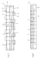
- a razor head in the form of a so-called razor blade unit for a wet shaver which can be attached to the front end of a handle, not shown, consists of a plastic body 1 in which two razor blades 2 are arranged, the cutting edges 3 of which run parallel and offset one behind the other.
- the plastic body 1 consists of a base part 4 with the razor blades 2 and an upper part 5 placed on this base part 4.
- the base part 4 of the plastic body 1 initially has feed-through slots 6 on the inside.
- the base part 4 defines a platform 7 for the razor blades 2.
- a spacer 8 is sandwiched between the two razor blades 2, the two razor blades 2 being firmly connected to this spacer 8. These thus form a razor blade / spacer / razor blade unit 9. This is placed on the platform 7 of the base part 4 from above, the spacer 8 projecting laterally for this purpose and being received in lateral recesses 10 of the base part 4.
- the unit 9 is held by means of a zigzag wire 11 which is guided over the top 12 of the unit 9 and thus the base part 4 of the plastic body 1.
- the base part 4 has on the front 13 in the lower area directed downward, formed projections 14, which are designed as elongated strips.
- the width of these projections 14 in the direction of the cutting edges 3 of the razor blades 2 essentially corresponds to the distance between the projections 14.
- the projections 14 In the front region, the projections 14 have a raised extension 15.
- the rear side 16 of the base part 4 has projections 14 ′ which are directed towards the rear. These projections 14 ′ fill the gaps between the projections 14 on the front 13. Corresponding to the projections 14, the projections 14 ' also have projections 15' which, however, are directed downwards. Finally, fastening projections 17 are integrally formed on the rear side 16 of the base part 4.
- the wire 11 is first fastened with its one end to a fastening projection 17. Then it is guided via the unit 9 to the front to the projection 14 and around it, in order to subsequently run back through 180 ° over the unit 9, where the wire 11 is guided around the projection 14 ′ there.
- the wire 11 is guided in succession around the projections 14 and 14 ′ in order to finally be attached at its other end to the attachment projection 17 on the other side of the base part 4.
- the sections of the wire 11 run parallel to one another in the region of the upper side 12 and at substantially constant intervals.
- the wire 11 on the one hand holds the unit 9 firmly on the platform 7 of the base part 4 and on the other hand prevents skin injuries.
- the upper part 5 is a one-piece plastic component and initially has a front guide bar 18. This extends parallel to the cutting edges 3 of the razor blades 2 and has a step-like longitudinal profile 19.
- a cover cap 20 is provided in the area.
- This has a sliding strip 21 on the upper side. This is convexly curved and initially has a first glide strip leg 22 and a second glide strip leg 22 ′, which is angled at an acute angle thereto, and which are connected to one another by an arc 23.
- the angle between the sliding strip legs 22, 22 ' can also be rectangular or obtuse.
- the two sliding strip legs 22, 22 ' are essentially flat or slightly convex. The production of such a sliding strip 21 is possible by means of a special hot molding process.
- this sliding strip 21 is also more effective at the end of the razor blade unit. Since the skin is stretched and pressed in during shaving, a bulge forms at the end of the razor blade unit. The sliding strip 21 shaped in the radius slides better in this area and thus increases the gentle shave.
- the front guide strip 18 and the rear cover cap 20 are connected to one another by side walls 24. Between these parts there is an opening 25 in the area of the cutting edges 3 of the razor blades 2, as can be seen in particular from the top view according to FIG. 1.
- Both the inside of the guide bar 18 and the inside of the cover cap 20 have receiving grooves 26 for the wire 11. Underneath the guide bar 18 there are recesses 27 which engage in a corresponding manner with the projections 14 of the base part 4. On the rear side, the upper part 5 formed from the guide strip 18, the cover cap 20 and the side walls 24 has through openings 28 which correspond to corresponding through openings in the spacer 8.
- the upper part 5 is plugged onto the base part 4 with the unit 9 fastened by the wire 11 and secured from above, for example by latching or in another way.
- the wire 11 runs therein.
- the course of the wire 11 in the area of the top 12 has the advantage that the bottom 29 of the plastic body 1 remains free and corresponding fastening systems can thus be provided.
Landscapes
- Life Sciences & Earth Sciences (AREA)
- Forests & Forestry (AREA)
- Engineering & Computer Science (AREA)
- Mechanical Engineering (AREA)
- Dry Shavers And Clippers (AREA)
- Knives (AREA)
Applications Claiming Priority (2)
| Application Number | Priority Date | Filing Date | Title |
|---|---|---|---|
| DE9004760U DE9004760U1 (de) | 1990-04-27 | 1990-04-27 | Rasierapparatekopf, insbesondere Rasierklingeneinheit, eines Naßrasierapparates |
| DE9004760U | 1990-04-27 |
Publications (2)
| Publication Number | Publication Date |
|---|---|
| EP0453717A1 true EP0453717A1 (fr) | 1991-10-30 |
| EP0453717B1 EP0453717B1 (fr) | 1994-01-26 |
Family
ID=6853256
Family Applications (1)
| Application Number | Title | Priority Date | Filing Date |
|---|---|---|---|
| EP91101819A Expired - Lifetime EP0453717B1 (fr) | 1990-04-27 | 1991-02-09 | Tête de rasage, particulièrement une unité de lames pour rasoir mécanique |
Country Status (7)
| Country | Link |
|---|---|
| US (1) | US5063668A (fr) |
| EP (1) | EP0453717B1 (fr) |
| AT (1) | ATE100753T1 (fr) |
| DE (2) | DE9004760U1 (fr) |
| DK (1) | DK0453717T3 (fr) |
| ES (1) | ES2050464T3 (fr) |
| HK (1) | HK65194A (fr) |
Cited By (3)
| Publication number | Priority date | Publication date | Assignee | Title |
|---|---|---|---|---|
| EP0556531A1 (fr) * | 1992-02-14 | 1993-08-25 | Wilkinson Sword Gesellschaft mit beschränkter Haftung | Tête de rasage, particulièrement une unité de lames pour rasoir mécanique |
| EP0559129A1 (fr) * | 1992-03-06 | 1993-09-08 | Wilkinson Sword Gesellschaft mit beschränkter Haftung | Tête de rasage pour rasoir mécanique |
| EP0563618A1 (fr) * | 1992-03-28 | 1993-10-06 | Wilkinson Sword Gesellschaft mit beschränkter Haftung | Tête de rasage pour rasoir mécanique |
Families Citing this family (8)
| Publication number | Priority date | Publication date | Assignee | Title |
|---|---|---|---|---|
| DE9201895U1 (de) * | 1992-02-14 | 1993-06-17 | Wilkinson Sword GmbH, 5650 Solingen | Rasierapparatekopf, insbesondere Rasierklingeneinheit, eines Naßrasierapparates |
| GB2265328B (en) * | 1992-03-13 | 1995-05-10 | Wilkinson Sword Gmbh | Razor head of a wet razor |
| US5630275A (en) * | 1994-08-23 | 1997-05-20 | Warner-Lambert Company | Multi-blade razor head with improved performance |
| US5456009A (en) * | 1994-08-23 | 1995-10-10 | Warner-Lambert Company | Multi-blade razor head with improved performance |
| JP2952587B1 (ja) * | 1998-03-30 | 1999-09-27 | 株式会社貝印刃物開発センター | 安全かみそり |
| US20040181949A1 (en) * | 2003-02-19 | 2004-09-23 | Eveready Battery Company, Inc. | Wet shaving cartridge with provision of shaving aid |
| JP2006521159A (ja) * | 2003-03-26 | 2006-09-21 | エヴァレディ バッテリー カンパニー インク | 針金付き刃セットを備えたウェットシェービング装置 |
| US7665199B2 (en) * | 2008-01-23 | 2010-02-23 | The Gillette Company | Method of making a razor blade unit |
Citations (5)
| Publication number | Priority date | Publication date | Assignee | Title |
|---|---|---|---|---|
| DE1909989A1 (de) * | 1968-02-28 | 1970-01-22 | Philip Morris Inc | Schneidklinge mit damit verbundenem Klingenschutz |
| GB2171630A (en) * | 1985-03-01 | 1986-09-03 | America Israel Blades Limited | Razor blade unit |
| DE8711506U1 (de) * | 1987-08-25 | 1987-10-08 | Wilkinson Sword GmbH, 5650 Solingen | Rasierklingeneinheit |
| US4875287A (en) * | 1986-11-14 | 1989-10-24 | Hydromer, Inc. | Shaving articles lubricious when wet and compositions therefor |
| EP0357821B1 (fr) * | 1988-09-08 | 1991-11-06 | Wilkinson Sword Gesellschaft mit beschränkter Haftung | Rasoir |
Family Cites Families (3)
| Publication number | Priority date | Publication date | Assignee | Title |
|---|---|---|---|---|
| US3872592A (en) * | 1974-01-30 | 1975-03-25 | Philip Morris Inc | Twin blade injector unit |
| DE3814135A1 (de) * | 1987-05-06 | 1988-11-24 | Wilkinson Sword Gmbh | Verfahren zur herstellung einer hydrophilen beschichtung auf einem formteil und unter anwendung des verfahrens hergestellter rasierapparat |
| DE8811356U1 (de) * | 1988-09-08 | 1988-10-20 | Wilkinson Sword GmbH, 5650 Solingen | Rasierapparatekopf, insbesondere Rasierklingeneinheit |
-
1990
- 1990-04-27 DE DE9004760U patent/DE9004760U1/de not_active Expired - Lifetime
-
1991
- 1991-02-09 ES ES91101819T patent/ES2050464T3/es not_active Expired - Lifetime
- 1991-02-09 DK DK91101819.0T patent/DK0453717T3/da active
- 1991-02-09 DE DE91101819T patent/DE59100928D1/de not_active Expired - Lifetime
- 1991-02-09 AT AT91101819T patent/ATE100753T1/de not_active IP Right Cessation
- 1991-02-09 EP EP91101819A patent/EP0453717B1/fr not_active Expired - Lifetime
- 1991-04-04 US US07/682,199 patent/US5063668A/en not_active Expired - Lifetime
-
1994
- 1994-07-07 HK HK65194A patent/HK65194A/xx not_active IP Right Cessation
Patent Citations (5)
| Publication number | Priority date | Publication date | Assignee | Title |
|---|---|---|---|---|
| DE1909989A1 (de) * | 1968-02-28 | 1970-01-22 | Philip Morris Inc | Schneidklinge mit damit verbundenem Klingenschutz |
| GB2171630A (en) * | 1985-03-01 | 1986-09-03 | America Israel Blades Limited | Razor blade unit |
| US4875287A (en) * | 1986-11-14 | 1989-10-24 | Hydromer, Inc. | Shaving articles lubricious when wet and compositions therefor |
| DE8711506U1 (de) * | 1987-08-25 | 1987-10-08 | Wilkinson Sword GmbH, 5650 Solingen | Rasierklingeneinheit |
| EP0357821B1 (fr) * | 1988-09-08 | 1991-11-06 | Wilkinson Sword Gesellschaft mit beschränkter Haftung | Rasoir |
Cited By (7)
| Publication number | Priority date | Publication date | Assignee | Title |
|---|---|---|---|---|
| EP0556531A1 (fr) * | 1992-02-14 | 1993-08-25 | Wilkinson Sword Gesellschaft mit beschränkter Haftung | Tête de rasage, particulièrement une unité de lames pour rasoir mécanique |
| US5305526A (en) * | 1992-02-14 | 1994-04-26 | Wilkinson Sword Gesellschaft Mit Beschrankter Haftung | Razor head, especially razor blade unit of a wet razor |
| EP0559129A1 (fr) * | 1992-03-06 | 1993-09-08 | Wilkinson Sword Gesellschaft mit beschränkter Haftung | Tête de rasage pour rasoir mécanique |
| EP0559130A1 (fr) * | 1992-03-06 | 1993-09-08 | Wilkinson Sword Gesellschaft mit beschränkter Haftung | Tête de rasage pour rasoir mécanique |
| US5447084A (en) * | 1992-03-06 | 1995-09-05 | Althaus; Wolfgang | Razor head of a wet razor |
| EP0563618A1 (fr) * | 1992-03-28 | 1993-10-06 | Wilkinson Sword Gesellschaft mit beschränkter Haftung | Tête de rasage pour rasoir mécanique |
| US5359774A (en) * | 1992-03-28 | 1994-11-01 | Warner-Lambert Company | Razor head of a wet razor |
Also Published As
| Publication number | Publication date |
|---|---|
| DE9004760U1 (de) | 1991-08-29 |
| HK65194A (en) | 1994-07-15 |
| DK0453717T3 (da) | 1994-05-30 |
| ES2050464T3 (es) | 1994-05-16 |
| ATE100753T1 (de) | 1994-02-15 |
| US5063668A (en) | 1991-11-12 |
| EP0453717B1 (fr) | 1994-01-26 |
| DE59100928D1 (de) | 1994-03-10 |
Similar Documents
| Publication | Publication Date | Title |
|---|---|---|
| EP0453906B1 (fr) | Tête de rasage, en particulier une unité de lames pour rasoir mécanique | |
| EP0521293B1 (fr) | Tête de rasage, en particulier une unité de lames pour rasoir mécanique | |
| EP0413143B1 (fr) | Tête de rasage, en particulier ensemble à lames pour rasoir mécanique | |
| EP0453718B1 (fr) | Tête de rasage, particulièrement une unité de lames pour rasoir mécanique | |
| DE3139693A1 (de) | Rasiergeraet | |
| DE3139761A1 (de) | Rasiergeraetgehaeuse | |
| DE2912381A1 (de) | Schneidgeraet | |
| EP0453717B1 (fr) | Tête de rasage, particulièrement une unité de lames pour rasoir mécanique | |
| EP0560239B1 (fr) | Tête de rasage pour rasor mécanique | |
| DE29516083U1 (de) | Klingenhalterung für einen Elektrorasierer | |
| DE3111871A1 (de) | Elektrischer rasierapparat | |
| DE2732401C2 (fr) | ||
| DE3151019C2 (de) | Vorrichtung zum Befestigen des oberen Umlenkbeschlages für einen Dreipunktsicherheitsgurt an der Karosserie eines Kraftfahrzeuges | |
| EP0559130B1 (fr) | Tête de rasage pour rasoir mécanique | |
| DE2510807B2 (de) | Elektrisches Gerät zur Befestigung an einer Unterlage | |
| EP1625912B1 (fr) | Dispositif à maillons de chaîne avec un petit radius de rotation | |
| DE2850811C2 (de) | Rotierende Schneideinheit für ein Trockenrasiergerät | |
| EP0605860B1 (fr) | Rasoir mécanique | |
| DE2638788A1 (de) | Sicherheitsrasierapparat | |
| DE69713106T2 (de) | Rasierer | |
| DE8420661U1 (de) | Elektrischer Hilfsanschluss | |
| DE3409732C2 (de) | Einbau-Aschenbecher für Kraftfahrzeuge | |
| DE2709889C3 (de) | Ringbuchheftvorrichtung | |
| DE8801506U1 (de) | Handwerkzeug | |
| DE2365398C3 (de) | Rastvorrichtung zur Schnittlängenverstelung eines Haarschneidegeräts |
Legal Events
| Date | Code | Title | Description |
|---|---|---|---|
| PUAI | Public reference made under article 153(3) epc to a published international application that has entered the european phase |
Free format text: ORIGINAL CODE: 0009012 |
|
| AK | Designated contracting states |
Kind code of ref document: A1 Designated state(s): AT BE CH DE DK ES FR GB GR IT LI LU NL SE |
|
| 17P | Request for examination filed |
Effective date: 19920127 |
|
| 17Q | First examination report despatched |
Effective date: 19920326 |
|
| GRAA | (expected) grant |
Free format text: ORIGINAL CODE: 0009210 |
|
| AK | Designated contracting states |
Kind code of ref document: B1 Designated state(s): AT BE CH DE DK ES FR GB GR IT LI LU NL SE |
|
| REF | Corresponds to: |
Ref document number: 100753 Country of ref document: AT Date of ref document: 19940215 Kind code of ref document: T |
|
| PGFP | Annual fee paid to national office [announced via postgrant information from national office to epo] |
Ref country code: AT Payment date: 19940222 Year of fee payment: 4 Ref country code: SE Payment date: 19940222 Year of fee payment: 4 |
|
| GBT | Gb: translation of ep patent filed (gb section 77(6)(a)/1977) |
Effective date: 19940124 |
|
| PGFP | Annual fee paid to national office [announced via postgrant information from national office to epo] |
Ref country code: NL Payment date: 19940228 Year of fee payment: 4 |
|
| ET | Fr: translation filed | ||
| PGFP | Annual fee paid to national office [announced via postgrant information from national office to epo] |
Ref country code: BE Payment date: 19940309 Year of fee payment: 4 |
|
| REF | Corresponds to: |
Ref document number: 59100928 Country of ref document: DE Date of ref document: 19940310 |
|
| PGFP | Annual fee paid to national office [announced via postgrant information from national office to epo] |
Ref country code: CH Payment date: 19940321 Year of fee payment: 4 |
|
| PGFP | Annual fee paid to national office [announced via postgrant information from national office to epo] |
Ref country code: DK Payment date: 19940331 Year of fee payment: 4 Ref country code: LU Payment date: 19940331 Year of fee payment: 4 |
|
| ITF | It: translation for a ep patent filed | ||
| REG | Reference to a national code |
Ref country code: GR Ref legal event code: FG4A Free format text: 3010768 |
|
| EPTA | Lu: last paid annual fee | ||
| REG | Reference to a national code |
Ref country code: ES Ref legal event code: FG2A Ref document number: 2050464 Country of ref document: ES Kind code of ref document: T3 |
|
| REG | Reference to a national code |
Ref country code: DK Ref legal event code: T3 |
|
| PLBE | No opposition filed within time limit |
Free format text: ORIGINAL CODE: 0009261 |
|
| STAA | Information on the status of an ep patent application or granted ep patent |
Free format text: STATUS: NO OPPOSITION FILED WITHIN TIME LIMIT |
|
| 26N | No opposition filed | ||
| EAL | Se: european patent in force in sweden |
Ref document number: 91101819.0 |
|
| PG25 | Lapsed in a contracting state [announced via postgrant information from national office to epo] |
Ref country code: LU Free format text: LAPSE BECAUSE OF NON-PAYMENT OF DUE FEES Effective date: 19950209 Ref country code: DK Effective date: 19950209 Ref country code: AT Effective date: 19950209 |
|
| REG | Reference to a national code |
Ref country code: DK Ref legal event code: EBP |
|
| PG25 | Lapsed in a contracting state [announced via postgrant information from national office to epo] |
Ref country code: SE Effective date: 19950210 |
|
| PG25 | Lapsed in a contracting state [announced via postgrant information from national office to epo] |
Ref country code: CH Effective date: 19950228 Ref country code: BE Effective date: 19950228 Ref country code: LI Effective date: 19950228 |
|
| BERE | Be: lapsed |
Owner name: WILKINSON SWORD G.M.B.H. Effective date: 19950228 |
|
| PG25 | Lapsed in a contracting state [announced via postgrant information from national office to epo] |
Ref country code: NL Effective date: 19950901 |
|
| NLV4 | Nl: lapsed or anulled due to non-payment of the annual fee |
Effective date: 19950901 |
|
| EUG | Se: european patent has lapsed |
Ref document number: 91101819.0 |
|
| PGFP | Annual fee paid to national office [announced via postgrant information from national office to epo] |
Ref country code: GR Payment date: 19961223 Year of fee payment: 7 |
|
| PGFP | Annual fee paid to national office [announced via postgrant information from national office to epo] |
Ref country code: ES Payment date: 19970220 Year of fee payment: 7 |
|
| PG25 | Lapsed in a contracting state [announced via postgrant information from national office to epo] |
Ref country code: ES Free format text: LAPSE BECAUSE OF EXPIRATION OF PROTECTION Effective date: 19980210 |
|
| PG25 | Lapsed in a contracting state [announced via postgrant information from national office to epo] |
Ref country code: GR Free format text: LAPSE BECAUSE OF NON-PAYMENT OF DUE FEES Effective date: 19980228 |
|
| REG | Reference to a national code |
Ref country code: ES Ref legal event code: FD2A Effective date: 20000601 |
|
| REG | Reference to a national code |
Ref country code: GB Ref legal event code: IF02 |
|
| PG25 | Lapsed in a contracting state [announced via postgrant information from national office to epo] |
Ref country code: IT Free format text: LAPSE BECAUSE OF NON-PAYMENT OF DUE FEES;WARNING: LAPSES OF ITALIAN PATENTS WITH EFFECTIVE DATE BEFORE 2007 MAY HAVE OCCURRED AT ANY TIME BEFORE 2007. THE CORRECT EFFECTIVE DATE MAY BE DIFFERENT FROM THE ONE RECORDED. Effective date: 20050209 |
|
| PGFP | Annual fee paid to national office [announced via postgrant information from national office to epo] |
Ref country code: FR Payment date: 20050217 Year of fee payment: 15 |
|
| REG | Reference to a national code |
Ref country code: FR Ref legal event code: ST Effective date: 20061031 |
|
| PG25 | Lapsed in a contracting state [announced via postgrant information from national office to epo] |
Ref country code: FR Free format text: LAPSE BECAUSE OF NON-PAYMENT OF DUE FEES Effective date: 20060228 |
|
| PGFP | Annual fee paid to national office [announced via postgrant information from national office to epo] |
Ref country code: DE Payment date: 20100226 Year of fee payment: 20 Ref country code: GB Payment date: 20100224 Year of fee payment: 20 |
|
| REG | Reference to a national code |
Ref country code: DE Ref legal event code: R071 Ref document number: 59100928 Country of ref document: DE |
|
| REG | Reference to a national code |
Ref country code: GB Ref legal event code: PE20 Expiry date: 20110208 |
|
| PG25 | Lapsed in a contracting state [announced via postgrant information from national office to epo] |
Ref country code: GB Free format text: LAPSE BECAUSE OF EXPIRATION OF PROTECTION Effective date: 20110208 |
|
| PG25 | Lapsed in a contracting state [announced via postgrant information from national office to epo] |
Ref country code: DE Free format text: LAPSE BECAUSE OF EXPIRATION OF PROTECTION Effective date: 20110209 |