EP0453736A1 - Szintillationskamera mit automatischem Gewichtskompensationstor - Google Patents
Szintillationskamera mit automatischem Gewichtskompensationstor Download PDFInfo
- Publication number
- EP0453736A1 EP0453736A1 EP91103098A EP91103098A EP0453736A1 EP 0453736 A1 EP0453736 A1 EP 0453736A1 EP 91103098 A EP91103098 A EP 91103098A EP 91103098 A EP91103098 A EP 91103098A EP 0453736 A1 EP0453736 A1 EP 0453736A1
- Authority
- EP
- European Patent Office
- Prior art keywords
- detector
- gantry
- camera
- collimator
- axis
- Prior art date
- Legal status (The legal status is an assumption and is not a legal conclusion. Google has not performed a legal analysis and makes no representation as to the accuracy of the status listed.)
- Granted
Links
- 230000005484 gravity Effects 0.000 claims description 5
- 230000005355 Hall effect Effects 0.000 claims 1
- 230000005855 radiation Effects 0.000 description 12
- 230000007246 mechanism Effects 0.000 description 8
- 230000033001 locomotion Effects 0.000 description 6
- 239000013078 crystal Substances 0.000 description 3
- FVAUCKIRQBBSSJ-UHFFFAOYSA-M sodium iodide Chemical compound [Na+].[I-] FVAUCKIRQBBSSJ-UHFFFAOYSA-M 0.000 description 3
- 230000006378 damage Effects 0.000 description 2
- 238000002603 single-photon emission computed tomography Methods 0.000 description 2
- 229910000831 Steel Inorganic materials 0.000 description 1
- 208000027418 Wounds and injury Diseases 0.000 description 1
- 230000005540 biological transmission Effects 0.000 description 1
- 210000004556 brain Anatomy 0.000 description 1
- 238000004891 communication Methods 0.000 description 1
- 238000010586 diagram Methods 0.000 description 1
- 208000014674 injury Diseases 0.000 description 1
- 230000003993 interaction Effects 0.000 description 1
- 230000007257 malfunction Effects 0.000 description 1
- 239000000463 material Substances 0.000 description 1
- 238000000034 method Methods 0.000 description 1
- 238000009206 nuclear medicine Methods 0.000 description 1
- 230000003287 optical effect Effects 0.000 description 1
- 238000005457 optimization Methods 0.000 description 1
- 210000000056 organ Anatomy 0.000 description 1
- 230000035945 sensitivity Effects 0.000 description 1
- 235000009518 sodium iodide Nutrition 0.000 description 1
- 239000010959 steel Substances 0.000 description 1
Images


Classifications
-
- A—HUMAN NECESSITIES
- A61—MEDICAL OR VETERINARY SCIENCE; HYGIENE
- A61B—DIAGNOSIS; SURGERY; IDENTIFICATION
- A61B6/00—Apparatus or devices for radiation diagnosis; Apparatus or devices for radiation diagnosis combined with radiation therapy equipment
- A61B6/44—Constructional features of apparatus for radiation diagnosis
- A61B6/4429—Constructional features of apparatus for radiation diagnosis related to the mounting of source units and detector units
- A61B6/447—Constructional features of apparatus for radiation diagnosis related to the mounting of source units and detector units the source unit or the detector unit being mounted to counterpoise or springs
-
- A—HUMAN NECESSITIES
- A61—MEDICAL OR VETERINARY SCIENCE; HYGIENE
- A61B—DIAGNOSIS; SURGERY; IDENTIFICATION
- A61B6/00—Apparatus or devices for radiation diagnosis; Apparatus or devices for radiation diagnosis combined with radiation therapy equipment
- A61B6/42—Arrangements for detecting radiation specially adapted for radiation diagnosis
- A61B6/4208—Arrangements for detecting radiation specially adapted for radiation diagnosis characterised by using a particular type of detector
- A61B6/4258—Arrangements for detecting radiation specially adapted for radiation diagnosis characterised by using a particular type of detector for detecting non x-ray radiation, e.g. gamma radiation
-
- G—PHYSICS
- G01—MEASURING; TESTING
- G01T—MEASUREMENT OF NUCLEAR OR X-RADIATION
- G01T1/00—Measuring X-radiation, gamma radiation, corpuscular radiation, or cosmic radiation
- G01T1/16—Measuring radiation intensity
- G01T1/161—Applications in the field of nuclear medicine, e.g. in vivo counting
- G01T1/164—Scintigraphy
- G01T1/1641—Static instruments for imaging the distribution of radioactivity in one or two dimensions using one or several scintillating elements; Radio-isotope cameras
- G01T1/1648—Ancillary equipment for scintillation cameras, e.g. reference markers, devices for removing motion artifacts, calibration devices
-
- A—HUMAN NECESSITIES
- A61—MEDICAL OR VETERINARY SCIENCE; HYGIENE
- A61B—DIAGNOSIS; SURGERY; IDENTIFICATION
- A61B6/00—Apparatus or devices for radiation diagnosis; Apparatus or devices for radiation diagnosis combined with radiation therapy equipment
- A61B6/02—Arrangements for diagnosis sequentially in different planes; Stereoscopic radiation diagnosis
- A61B6/03—Computed tomography [CT]
- A61B6/037—Emission tomography
Definitions
- the present invention relates to a scintillation camera, and more particularly relates to the mechanical structure of such a camera. In its most immediate sense, the invention relates to apparatus which adapts the camera for attachment of a collimator.
- a conventional scintillation camera such as a gamma camera includes a detector which converts into electrical signals gamma rays emitted from a patient after a radioisotope has been administered to the patient.
- the detector includes a scintillator and photodetectors.
- the gamma rays are directed to the scintillator (usually a crystal of thallium-doped sodium iodide) which absorbs the radiation and produces, in response, a minute flash of light.
- An array of photodetectors which are placed in optical communication with the scintillation crystal, converts these flashes to electrical signals which are subsequently processed. After processing, the camera produces an image of that region of the patient from which the radiation was emitted.
- a collimator which is a lead body perforated by relatively narrow channels.
- the collimator is detachably secured to the detector head, permitting the collimator to be changed so that, for example, the same camera can be used with different radioisotopes or different collimation patterns.
- a collimator may be quite massive, especially where it is intended for use with high-energy radioisotopes.
- the detector is conventionally rotated about the patient.
- the detector is also moved when positioning it to reach a fixed position to produce a planar image. In both instances, it is conventionally necessary to counterbalance the detector so that the rotation/movement does not place excessive loads on the drive motors which are used to move the detector.
- the camera has a movable counterweight which can be moved by rotating a manually-operable crank.
- Such manual adjustment of the counterweight is, however, insufficient to attain precise balance, and also restricts the weight range of collimators which can be attached to the detector, since the counterweight can only be adjusted within relatively narrow limits.
- One object of the invention is to provide a scintillation camera which places few constraints on the design of collimators which are to be used with it, thereby permitting the collimator design to be further optimized and providing improved results.
- Another object is to provide a scintillation camera which can be manually moved even though it may be attached to collimators of widely different weights.
- Still a further object is to provide a scintillation camera which will automatically counterbalance its gantry when the collimator is changed.
- Yet another object is, in general, to improve upon known scintillation cameras.
- a scintillation camera with a gantry and a detector secured to the gantry has means for counterbalancing the gantry. Means are provided to detachably secure a collimator to the detector. The camera also has means for identifying the collimator which is so secured. A control means is connected to the identifying means and the counterbalancing means. The counterbalancing means is automatically adjusted so as to appropriately counterbalance the gantry in accordance with the collimator which is secured to the detector.
- the counterbalancing means counterbalances the gantry with respect to two axes.
- one axis passes through the detector, and the other axis is parallel thereto.
- the gantry permits the detector to be rotated and is counterbalanced with respect to the axis of rotation.
- the gantry is counterbalanced with respect to three axes.
- the collimators which are designed for use in accordance with the invention are encoded using magnets, and Hall sensors in the detector head respond to the presence and absence of magnets to cause the counterbalancing mechanism in the camera to be appropriately adjusted.
- the collimators which are designed for use with the camera are not constrained to fit within a narrow weight range. Also, the automatic readjustment of the gantry in response to the actual weight of the attached collimator makes it possible to so accurately counterbalance the camera that it can be easily moved by hand.
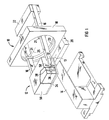
- Fig. 1 shows a perspective view of a preferred embodiment of the invention, generally designated by reference numeral 10.
- the scintillation camera apparatus 10 includes a detector generally designated by reference numeral 12.
- the detector 12 is protected by a housing 56, and is positioned to conduct nuclear medicine studies of a patient (not shown) lying on a cantilever table 14. (The table 14 is not part of the invention and is only shown for the sake of illustration.)
- the detector 12 is supported between the ends of a pair of parallel beams 16 so as to be rotatable on pivots 17 about an axis of rotation 13 (Fig. 5).
- a permanently affixed counterweight 22 is supported between the other ends of the beams 16, thereby counterbalancing the detector 12.
- the beams 16 are pivotally mounted intermediate their ends to a rotatable gantry ring 23 contained within a housing 18, the mounting being accomplished by yokes 21 so that the beams 16 can be tilted about a tilt axis 25 (which passes through the yokes 21).
- the gantry ring 23 is rotatable about plus or minus 360 o (i.e.
- the beams 16 can be tilted by plus 44 o or minus 30 o with respect to the horizontal plane. Because the gantry ring 23 is counterbalanced with respect to its axis of rotation, it may be rotated manually; it may alternatively be rotated by a motor (not shown). Tilting of the beams 16 may be carried out manually as a result of the counterbalancing system which is described below.
- the entire apparatus is supported by a base 20, upon which rests the housing 18 and mechanisms contained therein.
- a collimator 24 is used to collimate gamma radiation (not shown) which leaves the patient before the radiation is incident upon the scintillator (not shown) contained within the detector 12.
- Each collimator 24 (only one is shown) is of a material which absorbs gamma radiation, and each has a large number of open-ended empty channels which face the patient at one end and the detector 12 at the other.
- a hospital will own a plurality of collimators and the doctor or technician will select the one which is best suited for the study which is to be carried out.
- a relatively massive collimator will be used.
- a cone-beam or astigmatic collimator may be employed.
- each detector 12 is equipped with devices which permit a collimator to be mounted to, and locked on, the detector; these devices are not part of the present invention and have been omitted from the drawings for the sake of clarity.
- collimators will vary greatly depending upon the applications for which they are designed.
- a high energy collimator which is designed for 360 keV gamma radiation can weigh almost 190 kg, while a low energy collimator designed for 140 keV radiation can weigh only 40 kg, i.e. less than one-fourth as much.
- a high energy collimator may be designed to present a 7 cm thickness to incident radiation, while a low energy collimator may only present incident radiation with a 2.5 cm thickness or less. Consequently, if the detector 12 is to be easily moved by hand, greatly adjustable counterbalancing mechanisms must be employed to preserve counterbalancing of the detector 12 with whatever collimator may be employed.
- counterbalancing is accomplished with respect to three axes; axis 13 (through the detector 12, so that the detector can be manually pivoted on pivots 17), tilt axis 25 (so that the beams 16 may be tilted on the yokes 21) and the axis of rotation of the gantry ring 23 (so that the gantry ring 23 can be manually rotated about its axis).
- axis 13 through the detector 12, so that the detector can be manually pivoted on pivots 17
- tilt axis 25 tilt axis 25
- the axis of rotation of the gantry ring 23 so that the gantry ring 23 can be manually rotated about its axis.
- the general counterbalancing principle is to move the detector 12 with respect to axis 13 until the center of gravity of the detector 12 with the collimator 24 attached is aligned with the axis 13.
- each pivot 17 of the beams 16 is fixed to a drive nut 26.
- the drive nuts 26 are parallel to each other and extend parallel to the collimator 24 along the shorter sides of the detector 12.
- Each drive nut 26 is engaged by a threaded screw 28 which extends perpendicular to its corresponding drive nut 26; the screws 28 are parallel and are fixed to the detector 12 at their ends in such a manner as to permit them to be rotated. Such rotation is accomplished by the use of a chain drive mechanism.
- the chain drive mechanism includes a sprocket wheel 30 which is attached to each screw 28 at its end which is remote from the collimator 24.
- the sprocket wheels 30 are engaged by a chain 32 which is parallel to the collimator 24 and is located on the opposite side of the detector 12.
- the chain 32 is driven by a computer-controlled first motor 128 (not shown physically, but shown electrically in Fig. 6); the first motor 128 rotates a sprocket 36 which engages the chain 32 and causes it to move in either direction (as shown by the arrow in Fig. 5).
- the chain 32 is maintained in position by two sprocket wheels 34 which are located on either side of the sprocket 36 and which act as idlers.
- each drive nut 26 is engaged by, and guided by, two guide bars 38.
- Each pair of guide bars 38 is parallel to and located on either side of the corresponding screw 28 and passes through a linear bearing 40 which is mounted to the drive nut 26.
- the first motor 128 is rotated in the appropriate direction. This moves the chain 32, which rotates the sprocket wheels 30 and the screws 28, causing the detector 12 to slide along the four guide bars 38 with respect to the drive nuts 26. Movement continues until the center of gravity of the detector/collimator assembly is aligned with the axis 13.
- each beam 16 is hollow and accommodates a power transmission screw 44; the screws 44 are fixed at their ends to the beams 16 in such a manner that they are rotatable.
- the screws 44 are advantageously acme screws, and they extend along the axes of the beams 16.
- Each screw 44 supports and threadedly engages a counterweight 46.
- each counterweight 46 is a lead cylinder. The counterweights 46 are so mounted that they do not rotate within the beams 16, so that when the screws 44 are rotated, the counterweights 46 are axially shifted within their corresponding beams 16.
- the screws 44 are rotated by a chain drive. Each screw 44 extends beyond the rear end of the beam 16 and is connected to a sprocket wheel 48.
- a chain 50 drives the sprocket wheels 48.
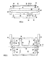
- the chain 50 is driven by a computer-controlled second motor 130 (not shown physically, but shown electrically in Fig. 6) which rotates a sprocket 54 in either direction (as is shown by the arrows in Fig. 4.)
- the chain 50 is maintained in position by sprocket wheels 52 which are located on either side of the sprocket 54 and which act as idlers.
- the second motor 130 is rotated in the appropriate direction. This rotates the sprocket 54, the sprocket wheels 48 and the screws 44, causing the counterweights 46 to be shifted within the beams. This shifting continues until the detector 12 is counterbalanced with respect to tilt axis 25.
- counterbalancing of the gantry about the axis of rotation of the gantry ring 23 is also accomplished using the above-described apparatus. This is accomplished by so choosing the dimensions and weights of the various components that a line connecting the center of gravity of the detector 12 and collimator 24 with the center of gravity of the counterweights 22 and 46 always passes through the center of the gantry ring 23. Thus, regardless of the weight of the collimator 24 which may be used, the gantry ring 23 will be manually rotatable.
- the scintillation camera gantry is automatically counterbalanced in accordance with the weight of the particular collimator 24 which has been selected.
- this is carried out by encoding each collimator 24 in such a way that the detector 12 can register its identity.
- the encoding is magnetic, but this is not necessary; other encoding techniques can be used instead.
- each collimator 24 is encoded with a seven bit code at the factory; the encoding represents the position to which the axis 13 must be moved to properly counterbalance the detector 12 (and thus represents the position to which the counterweights 46 must be moved to counterbalance the gantry with respect to the tilt axis 25).
- the seven bits (more or fewer bits may be used and the number of bits is not a part of the invention) are represented by seven predetermined locations on each collimator 24, and at each location a 1 or a 0 is represented by the presence or absence of a small magnet.
- An array 42 of magnetic sensors which may advantageously be Hall sensors, is mounted to the detector 12 in such a manner that each sensor will be directly adjacent its corresponding one of the seven locations on the collimator 24.
- the information represented by the magnets on the collimator 24 is thus read at the detector 12 and the counterbalancing of the gantry is correspondingly adjusted.
- the collimator 24 shown in Fig. 2 is heavier than is the collimator 24 shown in Fig. 3; as a result, the counterweights 46 are closer to the detector 12 in the Fig. 3 case than they are in the Fig. 2 case.
- the detector 12 is shifted higher with respect to the pivots 17 in the Fig. 2 case than it is in the Fig. 3 case.
- the gantry is so designed that it is counterbalanced, and therefore manually moveable, even when no collimator 24 is secured to the detector 12. This facilitates calibration of the detector 12; calibration is accomplished in the absence of a collimator 24.
- the gantry must contain much mechanical apparatus which does not appear in the foregoing Figures.
- all the movable parts must be equipped with "fail-safe" brakes which apply in the event of power failure and which positively prevent motion unless released, and limit switches, position sensors etc. are necessary to prevent damage to the apparatus or injury to the patient in the event of improper operation or equipment malfunction.
- this apparatus like much other necessary apparatus, is not part of the invention, and has been omitted from the Figures for the sake of simplicity.
- the table 14 is connected with the mechanism just described because it is often necessary to synchronize motion of the table 14 with motion and absence of motion of the camera gantry.
- electrical connections exist between the table 14 and the gantry so that both systems may be operated under common control.
- these connections, and the circuitry and electromechanical structure associated with them have been omitted from the Figures for the sake of simplicity since it is not a part of the present invention.
- the nonmechanical components in the preferred embodiment are shown in more detail in Fig. 6.
- the presence or absence of a magnet at each of these locations indicates a 1 or a 0 respectively; in this illustrative example, there are magnets at regions 102, 104 and 110.
- the corresponding regions on the detector 12 have Hall sensors 114, 116, 118, 120, 122, 124. and 126, which as a group form the array 42.
- the array 42 is connected to an on-board computerized controller 140 (which advantageously includes two computers, not shown, one for each of the motors 128 and 130).
- the controller 140 is connected to the first motor 128 and the second motor 130, as well as to appropriate other electromechanical mechanisms such as shaft encoders, brakes, limit switches, position sensors etc. which are collectively indicated by reference numeral 132. (Shaft encoders, not shown specifically, are advantageously used to monitor the positions of the shafts of the motors 128 and 130.)
- the controller 140 is also connected to a control panel indicated by reference numeral 134 and to various I/O ports collectively indicated by reference numeral 136.
- the ports 136 provide for, e.g., connections to the table 14, connection to hand-operated controls (not shown), connection to a computer (not shown), etc.
- the table 14 When a doctor or technician wishes to change the collimator 24 which is attached to the detector 12, the table 14 is moved out of the way and the detector 12 is moved over a collimator cart (not shown) on which the installed collimator is to be deposited. After the camera has been moved to an appropriate position and the appropriate switches, sensors etc. 132 are in states which indicate that the collimator 24 may be released from the detector 12 (as for example by an interaction between the collimator cart and a proximity switch on the detector 12) the collimator 24 is released, leaving it on the cart.
- the gantry counterbalancing is adjusted as necessary by operating the motors 128 and 130 under the control of the controller 140, the appropriate brakes etc.
- the detector 12 is then moved over the next collimator 24 which is to be installed on the detector 12. Once appropriate positioning of the detector 12 has been verified, the collimator 24 may be attached to the detector 12.
- the array 42 of Hall sensors responds to whatever magnets are located at the seven locations 100 - 112, the controller 140 operates the motors 128 and 130, and the gantry counterbalancing is appropriately adjusted so that appropriate counterbalancing exists between axes 13 and 25.
Landscapes
- Health & Medical Sciences (AREA)
- Life Sciences & Earth Sciences (AREA)
- Engineering & Computer Science (AREA)
- Medical Informatics (AREA)
- Physics & Mathematics (AREA)
- Biomedical Technology (AREA)
- General Health & Medical Sciences (AREA)
- High Energy & Nuclear Physics (AREA)
- Nuclear Medicine, Radiotherapy & Molecular Imaging (AREA)
- Optics & Photonics (AREA)
- Molecular Biology (AREA)
- Radiology & Medical Imaging (AREA)
- Heart & Thoracic Surgery (AREA)
- Pathology (AREA)
- Surgery (AREA)
- Animal Behavior & Ethology (AREA)
- Biophysics (AREA)
- Public Health (AREA)
- Veterinary Medicine (AREA)
- General Physics & Mathematics (AREA)
- Spectroscopy & Molecular Physics (AREA)
- Nuclear Medicine (AREA)
Applications Claiming Priority (2)
| Application Number | Priority Date | Filing Date | Title |
|---|---|---|---|
| US493566 | 1990-03-14 | ||
| US07/493,566 US5047641A (en) | 1990-03-14 | 1990-03-14 | Scintillation camera with automatically counterbalanced gantry |
Publications (2)
| Publication Number | Publication Date |
|---|---|
| EP0453736A1 true EP0453736A1 (de) | 1991-10-30 |
| EP0453736B1 EP0453736B1 (de) | 1994-06-01 |
Family
ID=23960765
Family Applications (1)
| Application Number | Title | Priority Date | Filing Date |
|---|---|---|---|
| EP91103098A Expired - Lifetime EP0453736B1 (de) | 1990-03-14 | 1991-03-01 | Szintillationskamera mit automatischem Gewichtskompensationstor |
Country Status (4)
| Country | Link |
|---|---|
| US (1) | US5047641A (de) |
| EP (1) | EP0453736B1 (de) |
| JP (1) | JPH04221783A (de) |
| DE (1) | DE69102194D1 (de) |
Families Citing this family (18)
| Publication number | Priority date | Publication date | Assignee | Title |
|---|---|---|---|---|
| FR2650397B1 (fr) * | 1989-07-28 | 1991-10-04 | Informatek Ste Nle | Dispositif a scintillation utilisable pour mesurer l'attenuation par tomographie de transmission |
| USD345606S (en) | 1990-11-21 | 1994-03-29 | Picker International, Inc. | Medical gamma camera gantry |
| US5289008A (en) * | 1992-06-10 | 1994-02-22 | Duke University | Method and apparatus for enhanced single photon computed tomography |
| US5262648A (en) * | 1993-02-10 | 1993-11-16 | Independent Scintillation Imaging Systems (Isis) Inc. | Medical diagnostic nuclear camera fork mounting with offset |
| US5670783A (en) * | 1996-02-15 | 1997-09-23 | Picker International, Inc. | Automated detector balance |
| CA2212196A1 (en) | 1997-08-01 | 1999-02-01 | Is2 Research Inc. | Medical diagnostic apparatus and method |
| US6373060B1 (en) * | 1998-01-30 | 2002-04-16 | Kabushiki Kaisha Toshiba | Nuclear medicine diagnostic apparatus |
| JP4521989B2 (ja) * | 2000-12-22 | 2010-08-11 | キヤノン株式会社 | 放射線画像撮影装置 |
| US6539333B1 (en) * | 2002-01-04 | 2003-03-25 | Leica Microsystems Ag | Stand having an automatic balancing device |
| CN101627320A (zh) * | 2006-11-20 | 2010-01-13 | 皇家飞利浦电子股份有限公司 | 探测器头接近度感测和碰撞避免装置及方法 |
| DE102010026375B4 (de) | 2010-07-07 | 2012-09-27 | Siemens Aktiengesellschaft | Strahlentherapiegerät und Verfahren zur Auswuchtung eines solchen |
| US8354649B2 (en) * | 2011-03-23 | 2013-01-15 | Elekta Ab (Publ) | Apparatus for the extension and retraction of a peripheral device |
| CN203634188U (zh) | 2013-11-14 | 2014-06-11 | 上海联影医疗科技有限公司 | 一种放射性医疗设备 |
| US9295439B2 (en) * | 2014-07-09 | 2016-03-29 | General Electric Company | Weight compensation of radiation detectors |
| US9392981B2 (en) | 2013-12-20 | 2016-07-19 | General Electric Company | Compact gantry system using independently controllable detectors |
| US9029791B1 (en) | 2013-12-20 | 2015-05-12 | General Electric Company | Imaging system using independently controllable detectors |
| US10441816B2 (en) | 2015-12-31 | 2019-10-15 | Shanghai United Imaging Healthcare Co., Ltd. | Radiation therapy system |
| US10213174B1 (en) | 2018-01-05 | 2019-02-26 | General Electric Company | Nuclear medicine imaging systems and methods having multiple detector assemblies |
Citations (3)
| Publication number | Priority date | Publication date | Assignee | Title |
|---|---|---|---|---|
| US3982133A (en) * | 1972-11-15 | 1976-09-21 | G. D. Searle & Co. | Collimator changer for scintillation camera |
| EP0109091A2 (de) * | 1982-11-16 | 1984-05-23 | Kabushiki Kaisha Toshiba | Aufhängung für eine Szintillationskamera |
| US4625116A (en) * | 1985-03-29 | 1986-11-25 | Siemens Gammasonics, Inc. | Structure for supporting a detector head |
Family Cites Families (2)
| Publication number | Priority date | Publication date | Assignee | Title |
|---|---|---|---|---|
| US4692625A (en) * | 1985-06-24 | 1987-09-08 | Siemens Gammasonics, Inc. | Detector head mounting mechanism and supporting structure |
| JPS62130371A (ja) * | 1985-12-03 | 1987-06-12 | Toshiba Corp | シンチレ−シヨンカメラ |
-
1990
- 1990-03-14 US US07/493,566 patent/US5047641A/en not_active Expired - Lifetime
-
1991
- 1991-03-01 DE DE69102194T patent/DE69102194D1/de not_active Expired - Lifetime
- 1991-03-01 EP EP91103098A patent/EP0453736B1/de not_active Expired - Lifetime
- 1991-03-13 JP JP3074713A patent/JPH04221783A/ja not_active Withdrawn
Patent Citations (3)
| Publication number | Priority date | Publication date | Assignee | Title |
|---|---|---|---|---|
| US3982133A (en) * | 1972-11-15 | 1976-09-21 | G. D. Searle & Co. | Collimator changer for scintillation camera |
| EP0109091A2 (de) * | 1982-11-16 | 1984-05-23 | Kabushiki Kaisha Toshiba | Aufhängung für eine Szintillationskamera |
| US4625116A (en) * | 1985-03-29 | 1986-11-25 | Siemens Gammasonics, Inc. | Structure for supporting a detector head |
Also Published As
| Publication number | Publication date |
|---|---|
| DE69102194D1 (de) | 1994-07-07 |
| JPH04221783A (ja) | 1992-08-12 |
| EP0453736B1 (de) | 1994-06-01 |
| US5047641A (en) | 1991-09-10 |
Similar Documents
| Publication | Publication Date | Title |
|---|---|---|
| US5047641A (en) | Scintillation camera with automatically counterbalanced gantry | |
| EP0532152B1 (de) | Regelbares Bildaufnahmesystem mit zwei Detektoren | |
| US5349190A (en) | Adjustable triple-detector image data acquisition system | |
| US4651007A (en) | Medical diagnostic mechanical positioner | |
| US3281598A (en) | Overhead support for a vertically and rotatably movable x-ray tube support arm and cooperating tiltable x-ray table | |
| EP0817978B1 (de) | Vielseitig einstellbare haltestruktur für szintillationskamera-systeme | |
| EP2271263B1 (de) | Quellen- und/oder detektorpositionierungssystem | |
| US7680249B2 (en) | Filter unit, X-ray tube unit, and X-ray imaging system | |
| US6175119B1 (en) | Photomultiplier tube identifier | |
| US20170040077A1 (en) | Apparatus and method for variable angle slant hole collimator | |
| EP0550628B1 (de) | Halterung für mehrfachszintillationskamera | |
| US5367169A (en) | Gamma camera with two opposite detectors having independent radial movements | |
| US4020348A (en) | Gantry scanning camera | |
| EP0511353B1 (de) | Anordnung von zwei drehbaren gamma-kameras | |
| US6590214B1 (en) | Collimator exchange system | |
| US7465928B2 (en) | Apparatus and methods for guiding cables around a rotating gantry of a nuclear medicine camera | |
| USRE37474E1 (en) | Adjustable dual-detector image data acquisition system | |
| USRE38560E1 (en) | Adjustable dual-detector image data acquisition system | |
| GB1597647A (en) | Gantry for computed tomography | |
| US5262648A (en) | Medical diagnostic nuclear camera fork mounting with offset | |
| Lanzl et al. | KILOCURIE REVOLVING COBALT-60 UNIT FOR RADIATION THERAPY* | |
| JPS60138485A (ja) | コリメーターを含む検出ヘツドの取付け機構 | |
| EP0109091A2 (de) | Aufhängung für eine Szintillationskamera | |
| CA2314205A1 (en) | Scintillation camera comprising at least three fields of view | |
| CA2326025A1 (en) | Scintillation camera comprising at least three fields of view |
Legal Events
| Date | Code | Title | Description |
|---|---|---|---|
| PUAI | Public reference made under article 153(3) epc to a published international application that has entered the european phase |
Free format text: ORIGINAL CODE: 0009012 |
|
| AK | Designated contracting states |
Kind code of ref document: A1 Designated state(s): DE FR GB NL |
|
| 17P | Request for examination filed |
Effective date: 19911127 |
|
| 17Q | First examination report despatched |
Effective date: 19930913 |
|
| GRAA | (expected) grant |
Free format text: ORIGINAL CODE: 0009210 |
|
| AK | Designated contracting states |
Kind code of ref document: B1 Designated state(s): DE FR GB NL |
|
| PG25 | Lapsed in a contracting state [announced via postgrant information from national office to epo] |
Ref country code: NL Effective date: 19940601 |
|
| REF | Corresponds to: |
Ref document number: 69102194 Country of ref document: DE Date of ref document: 19940707 |
|
| PG25 | Lapsed in a contracting state [announced via postgrant information from national office to epo] |
Ref country code: DE Effective date: 19940902 |
|
| ET | Fr: translation filed | ||
| NLV1 | Nl: lapsed or annulled due to failure to fulfill the requirements of art. 29p and 29m of the patents act | ||
| PG25 | Lapsed in a contracting state [announced via postgrant information from national office to epo] |
Ref country code: GB Effective date: 19950301 |
|
| PLBE | No opposition filed within time limit |
Free format text: ORIGINAL CODE: 0009261 |
|
| STAA | Information on the status of an ep patent application or granted ep patent |
Free format text: STATUS: NO OPPOSITION FILED WITHIN TIME LIMIT |
|
| 26N | No opposition filed | ||
| GBPC | Gb: european patent ceased through non-payment of renewal fee |
Effective date: 19950301 |
|
| PGFP | Annual fee paid to national office [announced via postgrant information from national office to epo] |
Ref country code: FR Payment date: 19980327 Year of fee payment: 8 |
|
| PG25 | Lapsed in a contracting state [announced via postgrant information from national office to epo] |
Ref country code: FR Free format text: LAPSE BECAUSE OF NON-PAYMENT OF DUE FEES Effective date: 19991130 |
|
| REG | Reference to a national code |
Ref country code: FR Ref legal event code: ST |