EP0453776A1 - Mécanisme de couplage avec disjoncteur ou sectionneur de charge et fusible - Google Patents
Mécanisme de couplage avec disjoncteur ou sectionneur de charge et fusible Download PDFInfo
- Publication number
- EP0453776A1 EP0453776A1 EP91104524A EP91104524A EP0453776A1 EP 0453776 A1 EP0453776 A1 EP 0453776A1 EP 91104524 A EP91104524 A EP 91104524A EP 91104524 A EP91104524 A EP 91104524A EP 0453776 A1 EP0453776 A1 EP 0453776A1
- Authority
- EP
- European Patent Office
- Prior art keywords
- switch
- fuse
- switching device
- switching
- auxiliary switch
- Prior art date
- Legal status (The legal status is an assumption and is not a legal conclusion. Google has not performed a legal analysis and makes no representation as to the accuracy of the status listed.)
- Granted
Links
- 230000013011 mating Effects 0.000 claims description 7
- 230000001960 triggered effect Effects 0.000 claims description 6
- 230000006835 compression Effects 0.000 claims description 5
- 238000007906 compression Methods 0.000 claims description 5
- 230000003111 delayed effect Effects 0.000 claims description 2
- 238000010586 diagram Methods 0.000 description 2
- 239000012530 fluid Substances 0.000 description 2
- 206010067482 No adverse event Diseases 0.000 description 1
- 230000033228 biological regulation Effects 0.000 description 1
- 230000007423 decrease Effects 0.000 description 1
- 230000000694 effects Effects 0.000 description 1
- 238000010438 heat treatment Methods 0.000 description 1
- 230000001939 inductive effect Effects 0.000 description 1
- 239000000155 melt Substances 0.000 description 1
- 238000013021 overheating Methods 0.000 description 1
- 230000036316 preload Effects 0.000 description 1
- 238000009423 ventilation Methods 0.000 description 1
Images

Classifications
-
- H—ELECTRICITY
- H02—GENERATION; CONVERSION OR DISTRIBUTION OF ELECTRIC POWER
- H02H—EMERGENCY PROTECTIVE CIRCUIT ARRANGEMENTS
- H02H7/00—Emergency protective circuit arrangements specially adapted for specific types of electric machines or apparatus or for sectionalised protection of cable or line systems, and effecting automatic switching in the event of an undesired change from normal working conditions
- H02H7/22—Emergency protective circuit arrangements specially adapted for specific types of electric machines or apparatus or for sectionalised protection of cable or line systems, and effecting automatic switching in the event of an undesired change from normal working conditions for distribution gear, e.g. bus-bar systems; for switching devices
- H02H7/222—Emergency protective circuit arrangements specially adapted for specific types of electric machines or apparatus or for sectionalised protection of cable or line systems, and effecting automatic switching in the event of an undesired change from normal working conditions for distribution gear, e.g. bus-bar systems; for switching devices for switches
-
- H—ELECTRICITY
- H01—ELECTRIC ELEMENTS
- H01H—ELECTRIC SWITCHES; RELAYS; SELECTORS; EMERGENCY PROTECTIVE DEVICES
- H01H9/00—Details of switching devices, not covered by groups H01H1/00 - H01H7/00
- H01H9/10—Adaptation for built-in fuses
- H01H9/106—Adaptation for built-in fuses fuse and switch being connected in parallel
Definitions
- the invention relates to a switching device according to the preamble of the first claim.
- the invention has for its object to take measures in a switching device according to the preamble of the first claim, by means of which the fuse is relieved of the effects of the operating current, the permissible overload current and the lower fault current range.
- an auxiliary switch short-circuits the fuse as long as the permissible current load values for the main switch are not exceeded. There is therefore no heating of the fuse by the rated transformer current, so that no heat loss arises. Short-term inrush currents or repeated residual current stresses just below the fuse tripping characteristic are also routed via the auxiliary switch so that the fuse cannot be damaged beforehand. Only in the extremely rare case of a larger fault current, in particular in the case of a primary-side short-circuit in the transformer, does the auxiliary switch release the short-circuit of the fuse, so that the fuse takes over the interruption of the overloaded circuit.
- the auxiliary switch has a straight line adjustable switching pin, which can be driven electromagnetically and can preferably be arranged mechanically parallel to the longitudinal axis of the fuse and, if appropriate, can be held on the poles of the fuse carrier.
- a magnetic coil can be connected to the circuit to be interrupted, which moves the switching pin into the contact disconnection position when the permissible current value is exceeded.
- the switching pin can also be locked in its switched-on position. Then, in the event of a fault, the associated locking device only needs to be unlocked, which can be done via the magnet coil already mentioned or the current transformer or other suitable sensors required for triggering the load-break switch.
- the drive of the switching pin can also be accomplished here via a suitable mechanical spring. After the fuse has blown and the disconnector has been opened, the auxiliary switch can be returned to its on position. This can be done automatically by the spring, against the force of which the switching pin was previously moved to the off position. The required reset delay can be achieved by a flow damper, which is assigned to the switching pin and reduces the speed of the reset movement sufficiently. However, the switching pin can also be locked in the off position, which can be triggered manually or via a time control device, so that the switching pin can return to its on position.
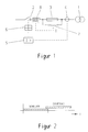
- the series circuit comprising a load break switch 2 as the main switch and a fuse 3 is placed.
- the fuse 3 is in particular a high-voltage high-current fuse, as is used in medium-voltage or high-voltage systems, and which has, for example, a switch-off time of 5 to 10 ms at a current load of 2 to 2.5 kiloamps.
- the switch-disconnector on the other hand, generally has a switch-off intrinsic time of 40 to 60 ms, so that it is ensured that the fuse has already interrupted the circuit when the high residual-current stress is triggered before the switch-disconnector in turn interrupts the circuit.
- a current transformer 4 is provided in the circuit to be switched, which delivers its control signal to an overload release 5, which controls a mechanical switch-off device 6 for the switch disconnector 2.
- the circuit is disconnected exclusively via switch disconnector 2.
- an auxiliary switch 7 is electrically connected in parallel, which causes a short circuit of the fuse 3 and is only opened in the event of short-circuit fault currents. Accordingly, this auxiliary switch should not be triggered in the normal operating and overload ranges even when the transformer 1 is switched on due to the short but high current pulses that occur. As a result, the fuse 3 remains practically unloaded and does not experience any significant change in its characteristic even over a long period of operation.
- the auxiliary switch 7 is consequently opened depending on the current value in the circuit to be switched when an admissible value is exceeded.
- its response time is dimensioned to be correspondingly long due to electrical delay means or mechanical inertia. This response delay must, however, take into account the switch-off time of the switch disconnector 2, taking into account the switch-off time of the fuse 3.
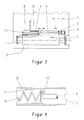
- the auxiliary switch 7 has a switching pin 9 which is mounted so as to be linearly displaceable and which is arranged mechanically parallel to the longitudinal axis of the fuse 3.
- the auxiliary switch 7 can be held on the poles 10 or 11 of the fuse or on the fuse carrier 12.
- the fixed contact 13 of the auxiliary switch 7 is electrically connected to the pole 10, while the switching pin 9 is electrically connected to the Pol 11 is interconnected.
- the contacts 9, 13 of the auxiliary switch 7 are located in an insulating tube in which a magnetic armature 14, which is mechanically firmly connected to the switching pin 9, is also displaceably mounted against the force of a compression spring 15.
- the compression spring 15 holds the switching pin 9 in engagement with the mating contact 13.
- the solenoid 8 is in such an arrangement that the armature 14 with the switching pin 9 is pulled away from the mating contact 13 when the flowing in the circuit to be switched Current i reaches a value at which the generated magnetic force pulls the armature 14 against the force of the prestressed compression spring 15 out of the counter contact 13.
- the magnetic coil 8 If, for example, a large fault current occurs which is above the permissible current value, the magnetic coil 8 generates a magnetic field which is so high that the magnetic armature 14 moves the switching pin 9 out of the mating contact 13. Since the fuse 3 is still intact, the auxiliary switch 7 switches off. Only after the switch contact path 9, 13 has been opened does the fuse 3 take over the full fault current and burns out in a time of 5 to 10 ms, at the same time the resulting arc is extinguished and the circuit is interrupted. The switching pin 9 of the auxiliary switch 7 has traveled a sufficiently long distance of, for example, 40 mm in the time until the fuse 3 has responded, which is sufficient to control the maximum possible switching voltage across the fuse 3.
- the switching pin 9 is assigned a flow damper which reduces the return speed, so that the auxiliary switch 7 can only get into the reclosing position after the main switch 2 has been opened.
- the flow damper can utilize the armature 14 as a piston and the relevant section 16 of the insulating tube enclosing the switching pin 9.
- the section 16, in which the spring 15 also lies, forms a closed cylinder, with either this cylinder 16 or the piston 14 being assigned a ventilation valve 17 which, when the switching pin 9 opens, allows the fluid enclosed in the cylinder 16 to flow largely unhindered. when moving in the opposite direction, however, at least largely closes the flow path, so that the previously displaced fluid can only slowly flow back into the cylinder 6 and, accordingly, the piston is slowly returned to the counter contact 13.
- the switch 2 has a current cut-off capacity which overlaps with the lower region of the tripping current of the fuse 3. It is thus ensured that a reliable interruption of the circuit to be switched is achieved at all current levels occurring during operation.
- the greatly delayed return of the switch pin 9 or its locking in the off position also ensures that the fused fuse is not short-circuited until the load-break switch 2 has reached an adequate disconnection position of its contact pieces for the operating voltage.
- An isolating circuit breaker is preferably provided as the main switch 2, which has a distinctive inductive switching capacity that ranges from about 0.1 to a few kiloamperes at a phase angle cosine phi. Such current conditions occur in particular when switching high-voltage power transformers 1.
- the nominal transformer current is approx. 18 amperes with a nominal transformer power of 630 kilovolt amperes and a nominal voltage of 24000 volts.
- a standard fuse 3 for high voltage with a list fuse nominal current of 50 amperes is used for this. According to the relevant regulations, this type of fuse has an approximately double minimum breaking current, i.e. approximately 100 amperes. From this one Current fuse melts 3 after several minutes at the earliest under permanent load.
- the response time decreases with increasing current load and is in the millisecond range at a current of approximately 2000 to 3000 amperes.
- Such currents only occur in the event of severe accidents in the high-voltage network, as a rule in the event of an arc short-circuit on the primary side of the transformer.
- the auxiliary switch 7 responds automatically and removes the bridging of the fuse 3.
- the fuse 3 is therefore only loaded with current when the current to be switched off has reached that characteristic range at which the fuse 3 responds in the shortest possible time of approximately 5 ms or disconnects the circuit.
- the auxiliary switch 7 With the auxiliary switch 7, the preload of the fuse 3 is cut off and only the reliable and quickly responding part is used by the fuse characteristic.
- the main switch switches all other, lower currents.
- a switching device In one embodiment of a switching device according to the invention, there is an overall economical solution in which a relatively simple main switch can be used. At the same time, the advantages of a fuse in the rarely occurring case of an unusual load are exploited and the fuse is also protected against damage from normal operating currents. An exchange of the fuse, which is time-consuming and costly, is thus restricted to these few extremely rare cases and the main switch need not be dimensioned for the maximum short-circuit current.
- An arrangement according to FIG. 5 can also be used as auxiliary switch 7, for example, in which dynamic current forces automatically cause the switching path to open.
- auxiliary switch 7 for example, in which dynamic current forces automatically cause the switching path to open.
- Contact arms 20 are provided, of which at least one, in the present case both, are pivotably mounted at adjacent ends about a respective pivot point 21.
- the contact arms 20 carry contact pieces 22.
- the contact arms 20 are pressed towards one another by mechanical springs 23 in such a way that the contact pieces 22 make contact.
- the contact arms 20 are carried by busbars 24, which are electrically and possibly also mechanically connected to the connections of the fuse 3 or its carrier 12.
- the contact arms 20, through which the short-circuit current flows, in parallel, are repelled by the magnetic current forces that occur against the force of the springs 23, and the contact path 22, 22 is opened.
- the inertia of the contact arms 20 can be chosen so large that a resetting or reclosing of the contacts 22 only occurs when the fuse 3 has interrupted the short-circuit current and the much slower main switch has opened its contact path. Means for delaying the resetting of the contact arms 20 are then not necessary, but can also be used. It is then ensured that the auxiliary switch does not close before the main switch has disconnected the circuit.
Landscapes
- Driving Mechanisms And Operating Circuits Of Arc-Extinguishing High-Tension Switches (AREA)
- Keying Circuit Devices (AREA)
- Switch Cases, Indication, And Locking (AREA)
- Fuses (AREA)
- Emergency Protection Circuit Devices (AREA)
Applications Claiming Priority (4)
| Application Number | Priority Date | Filing Date | Title |
|---|---|---|---|
| DE4012173 | 1990-04-14 | ||
| DE4012173 | 1990-04-14 | ||
| DE4023237 | 1990-07-21 | ||
| DE4023237A DE4023237A1 (de) | 1990-04-14 | 1990-07-21 | Schalteinrichtung mit einem lastschalter oder lasttrennschalter und einer sicherung |
Publications (2)
| Publication Number | Publication Date |
|---|---|
| EP0453776A1 true EP0453776A1 (fr) | 1991-10-30 |
| EP0453776B1 EP0453776B1 (fr) | 1995-07-05 |
Family
ID=25892269
Family Applications (1)
| Application Number | Title | Priority Date | Filing Date |
|---|---|---|---|
| EP91104524A Expired - Lifetime EP0453776B1 (fr) | 1990-04-14 | 1991-03-22 | Mécanisme de couplage avec disjoncteur ou sectionneur de charge et fusible |
Country Status (4)
| Country | Link |
|---|---|
| EP (1) | EP0453776B1 (fr) |
| JP (1) | JPH04230916A (fr) |
| DE (2) | DE4023237A1 (fr) |
| NO (1) | NO302988B1 (fr) |
Cited By (1)
| Publication number | Priority date | Publication date | Assignee | Title |
|---|---|---|---|---|
| EP1461818B1 (fr) * | 2001-12-31 | 2014-06-25 | ABB Technology AG | Systéme de limitation de courant défectueux |
Families Citing this family (8)
| Publication number | Priority date | Publication date | Assignee | Title |
|---|---|---|---|---|
| DE4417694A1 (de) * | 1994-05-20 | 1995-11-23 | Licentia Gmbh | Verfahren und Schaltungsanordnung zur Messung der Schaltzeit eines einen elektromagnetischen Auslöser enthaltenden Schaltgeräts |
| FR2782409B1 (fr) * | 1998-08-14 | 2002-11-29 | Schneider Electric Ind Sa | Transformateur immerge auto-protege par un dispositif incluant un disjoncteur et des fusibles |
| JP4587311B2 (ja) * | 2005-09-12 | 2010-11-24 | 日本電信電話株式会社 | 電流分配装置 |
| JP5054588B2 (ja) * | 2008-03-26 | 2012-10-24 | 日本電信電話株式会社 | 電流分配装置 |
| DE202015106368U1 (de) * | 2015-11-23 | 2017-02-24 | Phoenix Contatct GmbH & Co. KG | Verteilungssystem mit einer elektronischen Sicherungsklemme und zumindest einer ersten Reihenklemme |
| JP6255429B2 (ja) * | 2016-02-04 | 2017-12-27 | 矢崎総業株式会社 | 電流遮断装置及びワイヤハーネス |
| FR3098006B1 (fr) * | 2019-06-25 | 2021-07-09 | Mersen France Sb Sas | Coupe-circuit électrique |
| DE102021132463A1 (de) | 2021-12-09 | 2023-06-15 | Bayerische Motoren Werke Aktiengesellschaft | Sicherungsbauteil mit elektronischem Trennschalter und Schmelzleiter |
Citations (4)
| Publication number | Priority date | Publication date | Assignee | Title |
|---|---|---|---|---|
| CH311386A (de) * | 1953-02-10 | 1955-11-30 | Fkg Ag | Anordnung zur Begrenzung von Kurzschlussströmen in Gleich- und Wechselstromnetzen. |
| DE1050430B (fr) * | 1959-02-12 | |||
| US3309478A (en) * | 1965-09-15 | 1967-03-14 | Gen Electric | Multi-pole electric circuit breaker and fuse combination with single blownfuse sensing solenoid for all poles |
| DE3213090A1 (de) * | 1982-04-07 | 1983-10-20 | Matsushita Electric Works, Ltd., Kadoma, Osaka | Schaltungsschutzfuehler |
Family Cites Families (11)
| Publication number | Priority date | Publication date | Assignee | Title |
|---|---|---|---|---|
| DE613976C (de) * | 1932-04-26 | 1935-05-29 | Siemens Schuckertwerke Akt Ges | Schaltanordnung fuer eine elektrische Anlage |
| DE853770C (de) * | 1949-07-24 | 1952-10-27 | Voigt & Haeffner Ag | Daempfungspumpe fuer elektrische Schalter |
| DE1752494U (de) * | 1957-05-23 | 1957-09-19 | Fernschaltbau G M B H | Momentschaltgeraet. |
| DE1065060B (de) * | 1958-09-05 | 1959-09-10 | Voigt & Haeffner Ag | Daempfungspumpe fuer Kraftspeicherantrieb elektrischer Schaltgeraete |
| DE1198908B (de) * | 1962-12-12 | 1965-08-19 | Sachsenwerk Licht & Kraft Ag | Fluessigkeitsdaempfungspumpe fuer elektrische Leistungsschalter |
| US3414778A (en) * | 1966-01-03 | 1968-12-03 | Texas Instruments Inc | Solid state overload current controller |
| DE2634973A1 (de) * | 1976-08-04 | 1978-02-09 | Bbc Brown Boveri & Cie | Metallgekapselte, druckgasisolierte hochspannungsschaltanlage |
| DE3037740C2 (de) * | 1980-10-06 | 1982-08-26 | Licentia Patent-Verwaltungs-Gmbh, 6000 Frankfurt | Autopneumatischer SF↓6↓-Druckgasschalter mit pneumatischem Antrieb |
| DE3343424A1 (de) * | 1983-12-01 | 1985-06-13 | Felten & Guilleaume Energietechnik GmbH, 5000 Köln | Schutzeinrichtung fuer transformatorabgaenge im mittelspannungsbereich |
| DE3832171A1 (de) * | 1988-07-01 | 1990-01-04 | Licentia Gmbh | Einrichtung zur raschen ein- und ausschaltung von kleinen stroemen fuer trennschalter von v.i.s. |
| DE4000721C2 (de) * | 1989-01-14 | 1998-12-17 | Driescher Spezialfab Fritz | Mittelspannungs-Schaltanlage |
-
1990
- 1990-07-21 DE DE4023237A patent/DE4023237A1/de not_active Withdrawn
-
1991
- 1991-03-22 DE DE59105900T patent/DE59105900D1/de not_active Expired - Fee Related
- 1991-03-22 EP EP91104524A patent/EP0453776B1/fr not_active Expired - Lifetime
- 1991-04-12 NO NO911447A patent/NO302988B1/no unknown
- 1991-04-12 JP JP3079750A patent/JPH04230916A/ja active Pending
Patent Citations (4)
| Publication number | Priority date | Publication date | Assignee | Title |
|---|---|---|---|---|
| DE1050430B (fr) * | 1959-02-12 | |||
| CH311386A (de) * | 1953-02-10 | 1955-11-30 | Fkg Ag | Anordnung zur Begrenzung von Kurzschlussströmen in Gleich- und Wechselstromnetzen. |
| US3309478A (en) * | 1965-09-15 | 1967-03-14 | Gen Electric | Multi-pole electric circuit breaker and fuse combination with single blownfuse sensing solenoid for all poles |
| DE3213090A1 (de) * | 1982-04-07 | 1983-10-20 | Matsushita Electric Works, Ltd., Kadoma, Osaka | Schaltungsschutzfuehler |
Cited By (1)
| Publication number | Priority date | Publication date | Assignee | Title |
|---|---|---|---|---|
| EP1461818B1 (fr) * | 2001-12-31 | 2014-06-25 | ABB Technology AG | Systéme de limitation de courant défectueux |
Also Published As
| Publication number | Publication date |
|---|---|
| NO911447L (no) | 1991-10-15 |
| NO911447D0 (no) | 1991-04-12 |
| EP0453776B1 (fr) | 1995-07-05 |
| JPH04230916A (ja) | 1992-08-19 |
| DE59105900D1 (de) | 1995-08-10 |
| DE4023237A1 (de) | 1991-10-17 |
| NO302988B1 (no) | 1998-05-11 |
Similar Documents
| Publication | Publication Date | Title |
|---|---|---|
| DE69216179T2 (de) | Elektrisches Leistungsversorgungssystem | |
| WO2015039998A2 (fr) | Circuit pour onduleur photovoltaïque permettant l'équilibrage d'une mise hors circuit au moyen d'interrupteurs de court-circuit, et utilisations du circuit | |
| WO2010089338A2 (fr) | Dispositif de protection contre les courts-circuits et circuiterie présentant un dispositif de protection de ce type | |
| DE2854616C2 (de) | Selektivschutzeinrichtung | |
| EP0453776B1 (fr) | Mécanisme de couplage avec disjoncteur ou sectionneur de charge et fusible | |
| DE10244961B3 (de) | Selektiver Leitungsschutzschalter | |
| WO2005020259A1 (fr) | Appareil de protection de commutation securise | |
| EP1101234B1 (fr) | Systeme de protection contre les court-circuits | |
| DE4015979A1 (de) | Schalterkombination fuer lastschaltanlagen | |
| EP4521436A1 (fr) | Appareil de protection pour interrompre un circuit lors de la surintensité | |
| DE2854623A1 (de) | Anordnung zur selektiven abschaltung mehrerer verbraucher | |
| DE4108049C2 (de) | Schutzsystem für Nieder-, Mittel- oder Hochspannungsnetze mit hierarchisch gegliederten Netzebenen | |
| DE69108614T2 (de) | Abtrennbarer Überspannungsableiter für Niederspannungseinrichtungen. | |
| DE69723640T2 (de) | Elektrisches Verteilungsanschlusselement mit hybridem Begrenzerblock | |
| EP0468299B1 (fr) | Circuit avec un transformateur | |
| DE3133221A1 (de) | "leitungsschutzschalter" | |
| DE850018C (de) | Unterbrechungseinrichtung | |
| WO2017167514A1 (fr) | Agencement de circuits à fonction de déconnexion à minimum ou maximum de tension pour la protection de consommateurs, raccordés à un réseau polyphasés | |
| DE1082971B (de) | Wechselstromkurzschluesse selbsttaetig abschaltender Niederspannungs-Leistungsschalter | |
| DE3133200A1 (de) | Leitungsschutzschalter, geeignet als vorautomat | |
| DE102015106867A1 (de) | Auslösung eines Erdungsschalters einer Schaltanlage | |
| DE632431C (de) | UEberstromschnellschalter | |
| EP0504463A1 (fr) | Circuit pour alimentation en courant | |
| DE2702181A1 (de) | Kurzschluss-schutzschaltung fuer geraete mit halbleiterschaltern, insbesondere fuer lichtsteuergeraete | |
| DE4204559A1 (de) | Verfahren zur schaltspannungsbegrenzung |
Legal Events
| Date | Code | Title | Description |
|---|---|---|---|
| PUAI | Public reference made under article 153(3) epc to a published international application that has entered the european phase |
Free format text: ORIGINAL CODE: 0009012 |
|
| AK | Designated contracting states |
Kind code of ref document: A1 Designated state(s): BE DE FR GB IT NL |
|
| 17P | Request for examination filed |
Effective date: 19920311 |
|
| RAP1 | Party data changed (applicant data changed or rights of an application transferred) |
Owner name: AEG SACHSENWERK GMBH |
|
| 17Q | First examination report despatched |
Effective date: 19940509 |
|
| GRAA | (expected) grant |
Free format text: ORIGINAL CODE: 0009210 |
|
| AK | Designated contracting states |
Kind code of ref document: B1 Designated state(s): BE DE FR GB IT NL |
|
| REF | Corresponds to: |
Ref document number: 59105900 Country of ref document: DE Date of ref document: 19950810 |
|
| ET | Fr: translation filed | ||
| GBT | Gb: translation of ep patent filed (gb section 77(6)(a)/1977) |
Effective date: 19950829 |
|
| ITF | It: translation for a ep patent filed | ||
| PLBE | No opposition filed within time limit |
Free format text: ORIGINAL CODE: 0009261 |
|
| STAA | Information on the status of an ep patent application or granted ep patent |
Free format text: STATUS: NO OPPOSITION FILED WITHIN TIME LIMIT |
|
| 26N | No opposition filed | ||
| PGFP | Annual fee paid to national office [announced via postgrant information from national office to epo] |
Ref country code: FR Payment date: 19980317 Year of fee payment: 8 |
|
| PGFP | Annual fee paid to national office [announced via postgrant information from national office to epo] |
Ref country code: BE Payment date: 19980323 Year of fee payment: 8 |
|
| PGFP | Annual fee paid to national office [announced via postgrant information from national office to epo] |
Ref country code: NL Payment date: 19980330 Year of fee payment: 8 |
|
| PGFP | Annual fee paid to national office [announced via postgrant information from national office to epo] |
Ref country code: GB Payment date: 19980401 Year of fee payment: 8 |
|
| PG25 | Lapsed in a contracting state [announced via postgrant information from national office to epo] |
Ref country code: GB Free format text: LAPSE BECAUSE OF NON-PAYMENT OF DUE FEES Effective date: 19990322 |
|
| PG25 | Lapsed in a contracting state [announced via postgrant information from national office to epo] |
Ref country code: BE Free format text: LAPSE BECAUSE OF NON-PAYMENT OF DUE FEES Effective date: 19990331 |
|
| PGFP | Annual fee paid to national office [announced via postgrant information from national office to epo] |
Ref country code: DE Payment date: 19990529 Year of fee payment: 9 |
|
| BERE | Be: lapsed |
Owner name: AEG SACHSENWERK G.M.B.H. Effective date: 19990331 |
|
| PG25 | Lapsed in a contracting state [announced via postgrant information from national office to epo] |
Ref country code: NL Free format text: LAPSE BECAUSE OF NON-PAYMENT OF DUE FEES Effective date: 19991001 |
|
| GBPC | Gb: european patent ceased through non-payment of renewal fee |
Effective date: 19990322 |
|
| PG25 | Lapsed in a contracting state [announced via postgrant information from national office to epo] |
Ref country code: FR Free format text: LAPSE BECAUSE OF NON-PAYMENT OF DUE FEES Effective date: 19991130 |
|
| NLV4 | Nl: lapsed or anulled due to non-payment of the annual fee |
Effective date: 19991001 |
|
| REG | Reference to a national code |
Ref country code: FR Ref legal event code: ST |
|
| PG25 | Lapsed in a contracting state [announced via postgrant information from national office to epo] |
Ref country code: DE Free format text: LAPSE BECAUSE OF NON-PAYMENT OF DUE FEES Effective date: 20010103 |
|
| PG25 | Lapsed in a contracting state [announced via postgrant information from national office to epo] |
Ref country code: IT Free format text: LAPSE BECAUSE OF NON-PAYMENT OF DUE FEES Effective date: 20050322 |