EP0453791A1 - Plieuse à poches avec dispositif d'alimentation d'encarts - Google Patents
Plieuse à poches avec dispositif d'alimentation d'encarts Download PDFInfo
- Publication number
- EP0453791A1 EP0453791A1 EP91104717A EP91104717A EP0453791A1 EP 0453791 A1 EP0453791 A1 EP 0453791A1 EP 91104717 A EP91104717 A EP 91104717A EP 91104717 A EP91104717 A EP 91104717A EP 0453791 A1 EP0453791 A1 EP 0453791A1
- Authority
- EP
- European Patent Office
- Prior art keywords
- folding
- feed
- folded
- point
- insert
- Prior art date
- Legal status (The legal status is an assumption and is not a legal conclusion. Google has not performed a legal analysis and makes no representation as to the accuracy of the status listed.)
- Granted
Links
- 239000000463 material Substances 0.000 claims abstract description 37
- 238000000034 method Methods 0.000 claims abstract description 7
- 239000013589 supplement Substances 0.000 claims description 5
- 230000001360 synchronised effect Effects 0.000 claims description 3
- 230000008878 coupling Effects 0.000 claims 1
- 238000010168 coupling process Methods 0.000 claims 1
- 238000005859 coupling reaction Methods 0.000 claims 1
- 239000007795 chemical reaction product Substances 0.000 description 2
- 230000005284 excitation Effects 0.000 description 2
- 239000000853 adhesive Substances 0.000 description 1
- 230000001070 adhesive effect Effects 0.000 description 1
- 230000004888 barrier function Effects 0.000 description 1
- 230000000903 blocking effect Effects 0.000 description 1
- 230000006835 compression Effects 0.000 description 1
- 238000007906 compression Methods 0.000 description 1
- 238000007688 edging Methods 0.000 description 1
- 239000003292 glue Substances 0.000 description 1
- 239000002184 metal Substances 0.000 description 1
- 238000000926 separation method Methods 0.000 description 1
- 238000004804 winding Methods 0.000 description 1
Images


Classifications
-
- B—PERFORMING OPERATIONS; TRANSPORTING
- B65—CONVEYING; PACKING; STORING; HANDLING THIN OR FILAMENTARY MATERIAL
- B65H—HANDLING THIN OR FILAMENTARY MATERIAL, e.g. SHEETS, WEBS, CABLES
- B65H45/00—Folding thin material
- B65H45/12—Folding articles or webs with application of pressure to define or form crease lines
- B65H45/14—Buckling folders
- B65H45/142—Pocket-type folders
- B65H45/144—Pockets or stops therefor
-
- B—PERFORMING OPERATIONS; TRANSPORTING
- B65—CONVEYING; PACKING; STORING; HANDLING THIN OR FILAMENTARY MATERIAL
- B65H—HANDLING THIN OR FILAMENTARY MATERIAL, e.g. SHEETS, WEBS, CABLES
- B65H45/00—Folding thin material
- B65H45/12—Folding articles or webs with application of pressure to define or form crease lines
- B65H45/14—Buckling folders
- B65H45/142—Pocket-type folders
- B65H45/148—Pocket-type folders diverters therefor
-
- B—PERFORMING OPERATIONS; TRANSPORTING
- B65—CONVEYING; PACKING; STORING; HANDLING THIN OR FILAMENTARY MATERIAL
- B65H—HANDLING THIN OR FILAMENTARY MATERIAL, e.g. SHEETS, WEBS, CABLES
- B65H45/00—Folding thin material
- B65H45/12—Folding articles or webs with application of pressure to define or form crease lines
- B65H45/18—Oscillating or reciprocating blade folders
Definitions
- the invention relates to an upset folding machine with at least two folding points, each formed by a pair of folding rollers, a feed device for the folded material which determines the forward speed and consists of two feed rollers and which lies in a leading path provided with a forwarding limiting device which leads past the first folding point, one behind the feeding device the first fold point directed insert feed device and a fold pocket with a paper stop is arranged behind the first fold point.
- the known upset folding machines with insert feeders are each equipped with two folding pockets and adjusted so that they produce a folded fold.
- the paper deflectors that are common with upset folding machines, with which the inlet openings of the two folding pockets can be closed and the folded goods are each guided past a folding pocket to the next folding point, are not available in such buckle folding machines provided with insert feeding devices. They are not required because only the double-fold type is used.
- a pocketless paper folding machine is already known (DE 38 30 656 C1), in which a stop-free forward limiting device which determines the respective folding length and which is determined by a microprocessor and an electronic control device as a function of a forward measuring device is arranged in a conveying material feed path passing a folding point Folding process can be actuated individually and in which the folding material is deflected towards the folding points by knife-like or rod-shaped deflection elements at a speed corresponding to the feeding of the folding material.
- this known paper folding machine is not provided with an inserting device.
- a folding machine provided with two folding points and two folding pockets is known (DE 38 40 856 A1), in which a sheet guiding element driven by a linear motor and controlled by an electronic control is arranged between the first and second folding points.
- this folding machine does not have any insert addition device, which is why the sheet guiding element is only used to determine the type of fold.
- the invention is based on the object of designing an upset folding machine with an insert feed device of the type mentioned in such a way that different inserts can be inserted individually or together in the first and / or second fold of the folded material according to a program which can be entered.
- a second insert feed device (32 ') is arranged in front of the feeder device (T1, T2), the inserts of the first fold point (F1) being fed from a knife-like deflection member (6) to a stop-free flow limiting device which is fed with a
- the speed corresponding to the forwarding of the folded material can be moved towards the first folding point (F1) and is deflected by an electronic control device (21) in dependence on the fold-forming deflection (43, 55) a flow measuring device can be actuated individually for each folding process, and that for the direct feeding of the inserts to the second folding point (F2) directly in front of the folding pocket (25) as a second deflection element (26), an electromagnetically controllable folding material deflector is arranged, which after the folding material (43 , 55) into the folding pocket (25) while at the same time forming the folding material (43, 55) from a rest position that does not influence the folding material (43, 55) and the inserts toward the second folding point
- a folding machine equipped in this way solves the task with simple means. Their usability is considerably more variable than that of the known upset folding machines of the generic type. In addition, a high level of functional reliability and working speed is guaranteed.
- the inserts to be added optionally from the second insert feeding device can be added during the folding process in addition to the inserts from the first insert feeding device, for example directed towards the first folding point, or instead of the inserts from the first insert feeding device.
- the embodiment of the invention according to claim 2 ensures in a simple manner that the inserts fed from the second insert feed device arranged in front of the feeder device are guided directly from the feeder device to the first folding point, it being sensible to hold the deflecting member in the deflecting position for so long until the last third of the folded material has reached the first folding point, so that an insert that is fed from the second insert feed device to the second fold is reliably grasped by the two folding rollers forming the first folding point.
- the embodiment according to claim 3 contributes significantly to the functional reliability with regard to the insert separation and also to the increase in the working speed.
- the upset folding machine can be programmed in a simple manner both with regard to the folded material format and with regard to the addition of supplements.
- Folding machine are arranged in a frame 2 consisting of two plates 1 three folding rollers W1, W2 and W3 to each other so that their axes A1, A2 and A3 lie in the corners of a right-angled, isosceles triangle or in a horizontal plane E1 and in a vertical plane E2 and that they each form a first fold point F1 and a fold point F2 in pairs, in which the lateral surfaces of the folding rollers W1 and W2 or W2 and W3 touch.
- two feed rollers T1 and T2 form a feed point E, which is at the height of a horizontal paper guide 3.
- two further transport roller or transport rollers T3 and T4 are arranged, which together form an output point A through which the folded material leaves the folding machine again.
- the paper guide 3 with the feed point E is arranged so that the incoming folding material passes approximately tangentially via the first folding roller W1 past the first fold point F1 onto a second paper guide 3 ', which lies in the same horizontal plane as the feed point E, so that it together with this forms the leading path 4, indicated by a dash-dotted line and passing the first fold point F1.
- the knife-like deflection member 6 consists of a bent sheet metal part, and it has a rear guide web 5 which is directed against the feed point E and in the deflection position shown in FIG. 2 projects through the leading path 4 at an angle.
- the pivot levers 7 are in turn arranged on a common shaft 8 so that they are axially outside the two end faces of the folding roller W 1 and can thus be pivoted past the latter.
- the shaft 8 is mounted eccentrically to the axis A1 of the folding roller W1 below the advance path 4 between the folding roller W1 and the feed point E in the frame 2.
- two cam disks 10 are provided which are fastened on a shaft 9 mounted below the folding roller W1 and which have a single-speed clutch 14, which can be designed, for example, as a wrap spring clutch and can be brought into gear connection with the folding roller W1 at times via gear wheels 15 and 16 .
- the curve shape of the cams is designed in such a way that the deflection element 6 moves in synchronism between the cams 10 and the folding roller W1 at the forward speed of the folded material against the first fold point F1 and feeds the folded material to form the fold.
- the respective engagement of the one-way clutch 14 takes place by means of a pawl 17, which is actuated by an electromagnet 18 and, in its rest position, engages in a blocking manner under a locking shoulder 19 of a control ring 20 of the one-way clutch 14. If the electromagnet 18 is briefly energized, the pawl 17 releases the control ring for one revolution of the shaft 9 with the cams 10.
- the timely excitation of the electromagnet 18 is controlled by an electronic control device or with the aid of a microprocessor 21 as a function of a flow measuring device, not shown here.
- This flow measuring device includes a light barrier 22 in the flow path 4 and a pulse generator 23, both of which are connected to the microprocessor 21, by which the electromagnet 18 is controlled.
- the pulse generator 23 is synchronized with the folding rollers W1, W2, W3 or with the feed rollers T1, T2 and supplies 21 counting pulses to a programmable coincidence circuit of the microprocessor, the number of which represents a measure of the lead length.
- the microprocessor 21 or its coincidence circuit can be programmed and adjusted with the aid of an input keyboard 24 so that different fold lengths and different sheet lengths or different lead lengths can be set, depending on which the microprocessor 21 can address the electromagnet 18 in the event of coincidence.
- a second deflecting element 26 in the form of a paper deflector is arranged in the fold pocket 25 assigned to this fold point F1.
- This deflection member 26 is fastened to two pivot levers 27 of a shaft 26 'mounted in the frame 2 parallel to the folding rollers W1, W2, W3 and via an intermediate lever 28 from an electromagnet 29 from the rest position shown in FIGS 10c and 11c can be pivoted shown. In this swivel position, sheets of sheets and inserts arriving from the first folding point F1 can be directed past the folding pocket 25 directly to the second folding point F2.
- the intermediate lever 28 is pivotally mounted on a fixed bearing journal 30 and in each case articulatedly connected to one of the pivot levers 27 and the armature 31 of the electromagnet 29.
- the electromagnet 29 is also controlled by the microprocessor 21 according to the predetermined program.
- Both the separating devices 34 and 34 ', also the feed rollers 37, 38 and 37 ', 38', like the shaft 9 of the cam flanges 10, are driven via electromagnetically actuated clutches, the electromagnets 39, 40 and 41, 42 of which are controlled by the microprocessor 21 according to the program.
- the feed rollers preferably have a somewhat higher conveying speed than the feed rollers T1, T2 or the folding rollers W1, W2, W3.
- the waiting stations 33 and 33 'each have sheet guiding shafts 35 and 35', respectively, which are directed obliquely towards the advance track 4.
- the arrangement is such that the sheet guide shaft 35 of the first insert feed device 32 is directed directly at the first fold point F1 behind the feed rollers T1, T2 of the feeder device, while the sheet guide shaft 35 'of the second insert feed device 32' is arranged in front of the feed rollers T1 and T2 and is aimed directly at the collection point E.
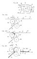
- FIG. 10 shows a sheet of folded material 43 which has already been folded twice in the manner of a wrap fold and partially opened again, the middle part 44 of which is provided with a viewing window 45.
- the address field 46 which is arranged on the inside of the lower sheet section 47, can be seen from the outside.
- the lower arch section 47 is provided with adhesive strips 48 only along its side edges
- the upper arch section 49 has glue strips 48 both along the side edges and along the transverse edge.
- the inside surface of the entire arch can be labeled.
- the not yet folded paper sheet 43 runs in the advance path 4 into the position shown in FIG. 10a.
- the folds 51 and 52 to be produced are indicated by small cross lines on the folded sheet 43.
- the pivoting lever 7 with the deflection element 6 is actuated by the cam disks 10 rotating once so that the exact position, at which the fold 51 is to be formed reaches the fold point F1, as is shown in FIG. 10b.
- the fold 51 formed in the fold point F1 then runs with the two adjoining arc sections 44 and 47 into the fold pocket 25 a.
- an insert 50 is fed from the waiting station 33 to the first insert feed device 32 by appropriate excitation of the electromagnet 41 from the feed rollers 37 and 38 in such a way that it arrives approximately simultaneously with the fold 52 or a little later in the fold point F1.
- the second deflecting member 26 is suddenly pivoted against the fold point F2, so that the fold 52 is steered together with the insert 50 into the fold point F2, and there is shown schematically in FIG. 10d Folded goods form with insert 50 inserted.
- the deflection element 6 would have had to remain in the position shown in FIG. 10b until the insert 50 caught the front edge of the fold point F1 would have been.
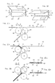
- the guide bar 5 is provided on the deflection element 6. This is because its task is to feed the inserts from the pre-feed path from the second insert feed device 32 ' 4 to the fold point F1, as shown in Fig. 11b.
- the viewing window 45 is attached in the upper sheet section 49 and the address field 46, which is to be read through this viewing window 45 in the folded state, on the outside of the lower sheet section 47.
- the one-dot-dash line in FIG. 11 In this case, insert 50 drawn in lines should already be added to the first fold 51 so that in the final state it comes to lie between the middle sheet section 44 and the lower sheet section 47, as shown in FIG. 11d.
- the insert 50 is fed from the second insert feed device 32 'in such a way that its front edge with the fold 51 reaches the fold point F1, when the first fold 51 is formed, it passes between the two sheet sections 44 and 47 and also runs into the folding pocket 25 between these two arc sections 44, 47.
- the deflection element 26 is pivoted back into its deflection position shown in FIG. 11c, so that the sheet of folded material 43 is deflected towards the second fold point F2 to form the second fold 52 and finally the end product shown in FIG. 11d is formed Wrapped fold, in which the insert 50 is added in the first fold 51.
- inserts 50 have a format that corresponds to approximately one third of the unfolded folded sheet format
- inserts the format of which corresponds to a two-thirds format of the folded sheet.
- Such an insert 54 is shown together with a folded sheet 55 in FIGS. 12 and 12a.
- the viewing window is arranged in the lower sheet section 47 and the address field 46 on the outside of the upper sheet section 49.
- the insert 54 is fed from the second insert feed device 32 'in such a way that the front edge of the insert 54 is in the vicinity of the fold 52 and that it is folded in half when the first fold 51 is formed in the fold point F1.
- the sheet of folded goods 55 is inserted into the feed point E in such a way that the lower sheet section 47 precedes and not, as in the examples above, the sheet section 49. Then the sheet of folded goods 55, as described above, is passed through together with the insert 54 the swiveling deflection element 6 is deflected into the first folding point F1, so that in this case the folded material sections 44 and 49 enter the folding pocket 25 and the folded insert 54 comes to lie between these two sheet sections 44 and 49. This is followed by a corresponding deflection of the deflecting member 26, the second fold in the folding point F2 and the end product shown in Fig. 12a schematically shown folded goods form with inserted insert 54.
- microprocessor 21 can also be easily programmed in such a fold type.
Landscapes
- Folding Of Thin Sheet-Like Materials, Special Discharging Devices, And Others (AREA)
Priority Applications (1)
| Application Number | Priority Date | Filing Date | Title |
|---|---|---|---|
| AT9191104717T ATE104644T1 (de) | 1990-04-23 | 1991-03-26 | Stauchfalzmaschine mit beilagenzufuehreinrichtung. |
Applications Claiming Priority (2)
| Application Number | Priority Date | Filing Date | Title |
|---|---|---|---|
| DE4012859 | 1990-04-23 | ||
| DE4012859A DE4012859C2 (de) | 1990-04-23 | 1990-04-23 | Stauchfalzmaschine mit Beilagenzuführeinrichtung |
Publications (2)
| Publication Number | Publication Date |
|---|---|
| EP0453791A1 true EP0453791A1 (fr) | 1991-10-30 |
| EP0453791B1 EP0453791B1 (fr) | 1994-04-20 |
Family
ID=6404883
Family Applications (1)
| Application Number | Title | Priority Date | Filing Date |
|---|---|---|---|
| EP91104717A Expired - Lifetime EP0453791B1 (fr) | 1990-04-23 | 1991-03-26 | Plieuse à poches avec dispositif d'alimentation d'encarts |
Country Status (5)
| Country | Link |
|---|---|
| US (1) | US5125633A (fr) |
| EP (1) | EP0453791B1 (fr) |
| JP (1) | JP2648403B2 (fr) |
| AT (1) | ATE104644T1 (fr) |
| DE (1) | DE4012859C2 (fr) |
Families Citing this family (10)
| Publication number | Priority date | Publication date | Assignee | Title |
|---|---|---|---|---|
| US5445368A (en) * | 1993-10-27 | 1995-08-29 | Pitney Bowes Inc. | Apparatus and method for forming collations of two different size documents |
| DE9404431U1 (de) * | 1994-03-16 | 1994-05-19 | Mathias Bäuerle GmbH, 78112 St Georgen | Vorrichtung zum Sammeln und Falzen mehrerer Papierbogen |
| DE19611788C2 (de) | 1996-03-12 | 1999-11-11 | Francotyp Postalia Gmbh | Anordnung zum Falzen von Bögen |
| DE19611787C2 (de) * | 1996-03-12 | 1999-11-11 | Francotyp Postalia Gmbh | Anordnung zum Falzen von Bögen |
| US5743517A (en) * | 1996-05-14 | 1998-04-28 | Bergeron; Eugene John | Loose signature ejector assembly in a folding apparatus |
| DE19747997A1 (de) * | 1997-10-30 | 1999-05-12 | Stahl Gmbh & Co Maschf | Taschenfalzwerk und Verfahren zur Registerregelung eines Taschenfalzwerks |
| JP3744234B2 (ja) * | 1998-11-10 | 2006-02-08 | コニカミノルタホールディングス株式会社 | シート後処理装置及び画像形成装置 |
| DE10132910A1 (de) * | 2001-06-28 | 2003-01-16 | Baeuerle Gmbh Mathias | Falzvorrichtung für Bogen aus Papier, Kunststoff und dergleichen |
| JP4189583B2 (ja) * | 2003-07-24 | 2008-12-03 | コニカミノルタビジネステクノロジーズ株式会社 | 用紙折り装置、用紙折り方法、後処理装置及び画像形成システム |
| WO2022137158A1 (fr) * | 2020-12-23 | 2022-06-30 | Dandekar Sanjay Madhav | Mécanisme pour empêcher le pliage d'un article intermédiaire dans une plieuse à couteau |
Citations (3)
| Publication number | Priority date | Publication date | Assignee | Title |
|---|---|---|---|---|
| US3416785A (en) * | 1966-01-24 | 1968-12-17 | Roneo Neopost Ltd | Paper nesting and enveloping apparatus |
| EP0297843A1 (fr) * | 1987-06-30 | 1989-01-04 | Iseto Shiko Co. Limited | Appareil pour manufacturer des envois postaux fermés ou enveloppes similaires |
| DE3830656C1 (fr) * | 1988-09-09 | 1989-11-23 | Mathias Baeuerle Gmbh, 7742 St Georgen, De |
Family Cites Families (9)
| Publication number | Priority date | Publication date | Assignee | Title |
|---|---|---|---|---|
| NL284451A (fr) * | 1961-10-18 | |||
| US3242637A (en) * | 1963-04-16 | 1966-03-29 | Kurt H Wills | Sheet folding and inserting apparatus |
| US3265382A (en) * | 1964-05-18 | 1966-08-09 | Herbert P Sherman | Paper nesting and enveloping apparatus |
| US3804399A (en) * | 1971-07-16 | 1974-04-16 | Chandler & Price Co | Auxiliary folder |
| US4270742A (en) * | 1978-03-27 | 1981-06-02 | Hiroshi Kobayashi | Paper stack binding and folding device |
| JPS62136478A (ja) * | 1985-12-04 | 1987-06-19 | Komori Printing Mach Co Ltd | 折機のチヨツパ装置 |
| DD269597A1 (de) * | 1987-12-29 | 1989-07-05 | Polygraph Leipzig | Linearmotorantrieb fuer bogenleitelemente |
| US4900391A (en) * | 1988-12-19 | 1990-02-13 | Xerox Corporation | Recirculating folder for direct mail application |
| US5044617A (en) * | 1989-02-28 | 1991-09-03 | M.B.O. Binder And Company Of America | Sheet folding apparatus having air deflector means |
-
1990
- 1990-04-23 DE DE4012859A patent/DE4012859C2/de not_active Expired - Fee Related
-
1991
- 1991-03-26 AT AT9191104717T patent/ATE104644T1/de not_active IP Right Cessation
- 1991-03-26 EP EP91104717A patent/EP0453791B1/fr not_active Expired - Lifetime
- 1991-04-19 JP JP3088222A patent/JP2648403B2/ja not_active Expired - Lifetime
- 1991-04-22 US US07/689,307 patent/US5125633A/en not_active Expired - Lifetime
Patent Citations (3)
| Publication number | Priority date | Publication date | Assignee | Title |
|---|---|---|---|---|
| US3416785A (en) * | 1966-01-24 | 1968-12-17 | Roneo Neopost Ltd | Paper nesting and enveloping apparatus |
| EP0297843A1 (fr) * | 1987-06-30 | 1989-01-04 | Iseto Shiko Co. Limited | Appareil pour manufacturer des envois postaux fermés ou enveloppes similaires |
| DE3830656C1 (fr) * | 1988-09-09 | 1989-11-23 | Mathias Baeuerle Gmbh, 7742 St Georgen, De |
Also Published As
| Publication number | Publication date |
|---|---|
| ATE104644T1 (de) | 1994-05-15 |
| JP2648403B2 (ja) | 1997-08-27 |
| DE4012859C2 (de) | 1993-12-16 |
| EP0453791B1 (fr) | 1994-04-20 |
| JPH04223974A (ja) | 1992-08-13 |
| US5125633A (en) | 1992-06-30 |
| DE4012859A1 (de) | 1991-10-24 |
Similar Documents
| Publication | Publication Date | Title |
|---|---|---|
| EP0059357B1 (fr) | Plieuse | |
| EP0768267B1 (fr) | Plieuse à poches avec un sac de pliage et de stockage | |
| DE69909387T2 (de) | Kuvertiermaschine mit getrenntem Weg für Beilagen | |
| DE3911423C2 (de) | Vorrichtung zum Transport eines Umschlages in einer Umschlag-Beschickungseinrichtung | |
| EP2727869B1 (fr) | Dispositif et procédé destinés à plier des feuilles imprimées | |
| EP0357948B1 (fr) | Plieuse pour papier | |
| EP0453791B1 (fr) | Plieuse à poches avec dispositif d'alimentation d'encarts | |
| EP0473902A1 (fr) | Dispositif d'agrafage de produits imprimés composés | |
| DE4123499A1 (de) | Vorrichtung zur papierfuehrung an einem weiterverarbeitungsgeraet fuer kopieblaetter | |
| DE69409596T2 (de) | Vorrichtung zum Zickzackfalten von Bogen | |
| EP0675008B1 (fr) | Machine à mettre sous enveloppe avec un approvisionnement réglable et facultatif des inserts et des enveloppes à partir de postes d'apprivisionnement multiples | |
| EP2165957B1 (fr) | Procédé et dispositif destinés à plier des feuilles | |
| DE69804183T2 (de) | Kuvertiermaschine mit optimisierten Wegen für die Dokumente | |
| DE69312896T2 (de) | Einrichtung und Verfarhen zum Kuvertieren einer Gesammtheit von Dokumenten | |
| CH694556A5 (de) | Verpackungsstrasse für gestapelte Druckprodukte, wie Zeitschriften oder Magazine. | |
| EP0354176A1 (fr) | Machine à plier les feuilles de papier | |
| EP2727868A1 (fr) | Dispositif et procédé destinés à plier des feuilles imprimées | |
| DE2434360A1 (de) | Vorrichtung zum stapeln loser papierboegen | |
| DE19522131C2 (de) | Transportvorrichtung für Blätter | |
| EP2176151A1 (fr) | Procédé et dispositif pour produire une bande pliée | |
| DE69302494T2 (de) | Vorrichtung und Verfahren zum Falten von Bogen mit verschiedenen Formaten | |
| WO1998035901A1 (fr) | Dispositif pour produire des imprimes en plusieurs parties | |
| DE1436595A1 (de) | Bogenfalzmaschine | |
| DE10314791B4 (de) | Medienfalten | |
| DE9104607U1 (de) | Vorrichtung zum Sammeln und Falzen von Papierbogen |
Legal Events
| Date | Code | Title | Description |
|---|---|---|---|
| PUAI | Public reference made under article 153(3) epc to a published international application that has entered the european phase |
Free format text: ORIGINAL CODE: 0009012 |
|
| AK | Designated contracting states |
Kind code of ref document: A1 Designated state(s): AT BE CH FR GB IT LI LU NL SE |
|
| 17P | Request for examination filed |
Effective date: 19920331 |
|
| 17Q | First examination report despatched |
Effective date: 19931011 |
|
| GRAA | (expected) grant |
Free format text: ORIGINAL CODE: 0009210 |
|
| AK | Designated contracting states |
Kind code of ref document: B1 Designated state(s): AT BE CH FR GB IT LI LU NL SE |
|
| PG25 | Lapsed in a contracting state [announced via postgrant information from national office to epo] |
Ref country code: FR Free format text: THE PATENT HAS BEEN ANNULLED BY A DECISION OF A NATIONAL AUTHORITY Effective date: 19940420 |
|
| REF | Corresponds to: |
Ref document number: 104644 Country of ref document: AT Date of ref document: 19940515 Kind code of ref document: T |
|
| ET | Fr: translation filed | ||
| GBT | Gb: translation of ep patent filed (gb section 77(6)(a)/1977) |
Effective date: 19940420 |
|
| ITF | It: translation for a ep patent filed | ||
| EAL | Se: european patent in force in sweden |
Ref document number: 91104717.3 |
|
| PLBE | No opposition filed within time limit |
Free format text: ORIGINAL CODE: 0009261 |
|
| STAA | Information on the status of an ep patent application or granted ep patent |
Free format text: STATUS: NO OPPOSITION FILED WITHIN TIME LIMIT |
|
| PG25 | Lapsed in a contracting state [announced via postgrant information from national office to epo] |
Ref country code: GB Effective date: 19950326 Ref country code: AT Effective date: 19950326 |
|
| PG25 | Lapsed in a contracting state [announced via postgrant information from national office to epo] |
Ref country code: SE Effective date: 19950327 |
|
| PG25 | Lapsed in a contracting state [announced via postgrant information from national office to epo] |
Ref country code: LU Free format text: LAPSE BECAUSE OF NON-PAYMENT OF DUE FEES Effective date: 19950331 Ref country code: LI Effective date: 19950331 Ref country code: CH Effective date: 19950331 Ref country code: BE Effective date: 19950331 |
|
| 26N | No opposition filed | ||
| BERE | Be: lapsed |
Owner name: MATHIAS BAUERLE G.M.B.H. Effective date: 19950331 |
|
| PG25 | Lapsed in a contracting state [announced via postgrant information from national office to epo] |
Ref country code: NL Effective date: 19951001 |
|
| GBPC | Gb: european patent ceased through non-payment of renewal fee |
Effective date: 19950326 |
|
| REG | Reference to a national code |
Ref country code: CH Ref legal event code: PL |
|
| NLV4 | Nl: lapsed or anulled due to non-payment of the annual fee |
Effective date: 19951001 |
|
| EUG | Se: european patent has lapsed |
Ref document number: 91104717.3 |
|
| REG | Reference to a national code |
Ref country code: FR Ref legal event code: ST |
|
| PG25 | Lapsed in a contracting state [announced via postgrant information from national office to epo] |
Ref country code: IT Free format text: LAPSE BECAUSE OF NON-PAYMENT OF DUE FEES;WARNING: LAPSES OF ITALIAN PATENTS WITH EFFECTIVE DATE BEFORE 2007 MAY HAVE OCCURRED AT ANY TIME BEFORE 2007. THE CORRECT EFFECTIVE DATE MAY BE DIFFERENT FROM THE ONE RECORDED. Effective date: 20050326 |