EP0453794B1 - Appareil et procédé pour fixer une plaque d'impression sur un cylindre de fente étroite - Google Patents
Appareil et procédé pour fixer une plaque d'impression sur un cylindre de fente étroite Download PDFInfo
- Publication number
- EP0453794B1 EP0453794B1 EP91104754A EP91104754A EP0453794B1 EP 0453794 B1 EP0453794 B1 EP 0453794B1 EP 91104754 A EP91104754 A EP 91104754A EP 91104754 A EP91104754 A EP 91104754A EP 0453794 B1 EP0453794 B1 EP 0453794B1
- Authority
- EP
- European Patent Office
- Prior art keywords
- tail member
- gap
- mounting arrangement
- curved
- tail
- Prior art date
- Legal status (The legal status is an assumption and is not a legal conclusion. Google has not performed a legal analysis and makes no representation as to the accuracy of the status listed.)
- Expired - Lifetime
Links
- 238000000034 method Methods 0.000 title claims description 4
- 238000003825 pressing Methods 0.000 claims description 7
- 230000013011 mating Effects 0.000 claims description 6
- 238000005452 bending Methods 0.000 claims description 5
- 238000004891 communication Methods 0.000 claims description 4
- 229910000831 Steel Inorganic materials 0.000 description 2
- 230000001154 acute effect Effects 0.000 description 2
- 239000010959 steel Substances 0.000 description 2
- 230000000712 assembly Effects 0.000 description 1
- 238000000429 assembly Methods 0.000 description 1
- 230000000694 effects Effects 0.000 description 1
- 238000003780 insertion Methods 0.000 description 1
- 230000037431 insertion Effects 0.000 description 1
- 238000004519 manufacturing process Methods 0.000 description 1
- 239000000463 material Substances 0.000 description 1
Images

Classifications
-
- B—PERFORMING OPERATIONS; TRANSPORTING
- B41—PRINTING; LINING MACHINES; TYPEWRITERS; STAMPS
- B41F—PRINTING MACHINES OR PRESSES
- B41F27/00—Devices for attaching printing elements or formes to supports
- B41F27/12—Devices for attaching printing elements or formes to supports for attaching flexible printing formes
- B41F27/1281—Devices for attaching printing elements or formes to supports for attaching flexible printing formes details of the printing plate ends
Definitions
- This invention relates to a printing plate mounting apparatus for releasibly connecting a printing plate to a rotary cylinder of a printing press and, more particularly, to such a mounting apparatus in which the plate is mounted by means of tail members at opposite ends which are held within a longitudinal mounting gap in the surface of the cylinder.
- the smallest gaps which can be used are at least ten times the thickness of the plates. Specifically, the smallest gap known to operate successfully is approximately 3 mm (123 mils) thick.
- the tail members are both substantially planar and extend at acute angles to overlie the printing plate body.
- the tail at the leading edge is inserted in the gap and hooks around an edge.
- the flexible body is then wrapped around the cylinder until the tail at the opposite end of the body is located opposite the gap. It is then inserted in the gap alongside the leading edge tail member and locked in place.
- the gaps are so large, the locking mechanism often must longitudinally strain the tail member to keep it in place which can cause distortion of the tail member. This distortion is preferably avoided since it can cause jamming of the tail member within the slot and hinder or prevent subsequent removal even when the gap is relatively large.
- attempts to reduce the gap to less than a minimum gap size of approximatley 3 mm (123 mils) results in difficulties in inserting the one tail member in the gap after the other tail has already been inserted.
- small gap sizes can create unacceptable difficulties in removing the tail members after insertion with known printing plates.
- a plate cylinder arranged for mounting intaglio printing plates for web-fed printing machines comprises at least one groove opening at its periphery.
- a fastening device is disposed in the groove opening for opposed plate ends extending into the groove.
- the tail member at one of the opposite ends of the plate is substantially curved and in contact with a tightening bar disposed in the groove opening.
- the tightening bar abuts against the bottom of the groove, and its tapered end extends almost to the envelope of the generated surface of the plate cylinder.
- the tapered end lies in the circumferential gap formed by the outwardly tapering groove where it opens out at the cylinder periphery.
- Pistons strike the tightening bar which is thus thrust toward the opposed wall of the groove.
- a clamping piece is located between this opposed wall and the tightening bar.
- the wall of the groove on the side of the tighening bar remote from the clamping piece is substantially planar.
- the surface thereof on the side of the clamping piece which acts as a contact surface, is adapted to the curvature of the tail member with the exception of a radially inner section.
- the surface is slightly angled to form an edge, in order to increase the clamping effect on the curved tail member of the plate extending over this edge.
- US-A-3,408,933 discloses a cylinder for a blanket in a printing press in which the ends of the blanket are received in a groove having an access slot comprising opposed planar surfaces used as undercut seating surfaces for the opposed ends of the blanket.
- the known cylinder comprises a leaf spring for gripping a respective end of the blanket and a takeup spring for applying force against the leaf spring so that the latter applies a first component normal to the surface and a second component along the surface to take up any slack developing in the blanket under running conditions.
- the blanket is tightened at its ends received in the groove in a direction parallel to the planar groove walls.
- a printing plate having a planar body extending between a pair of opposite ends for mounting to the surface of a rotary cylinder of a printing press by means of a mounting gap for holding the body to the cylinder at said opposite ends with a narrow gap plate mounting apparatus.
- the narrow gap plate mounting apparatus comprising a first tail member at one of said opposite ends and extending away from the planar body for receipt within the mounting gap, and a second tail member at the other one of said opposite ends and extending away from the planar body for receipt within the mounting gap together with the substantially planar tail member, which unlike known planar tail members, is substantially curved.
- the curved shape is at least approximately involute, i.e. the locus of a fixed point on a taut, inextensible string as it unwinds from a fixed plane curve.
- the substantially curved tail member includes a plurality of substantially planar tail member segments interconnected to approximate the curved shape of the substantially curved tail member.
- a narrow gap mounting apparatus including a cavity within a printing press cylinder and in communication with the gap which has a substantially curved wall to mate with the substantially curved one of the tail members received through the mounting slot and means for pressing the curved one of the tails against the curved wall to hold it within the cavity.
- An improved method of mounting a printing plate to a cylinder of a rotary printing press is then also provided which enables use of a much narrower gap than previously could be used comprising the steps of bending the opposite ends of printing plate stock to form a pair of first and second mounting tail members at opposite ends of an intermediate planar body with the second tail member being bent in a curved shape inserting the first tail member in a mounting slot in the cylinder conveying the intermediate body around the cylinder and inserting the second, curved tail member into the slot between a lagging edge of the slot and the first tail member.
- the second tail member is bent in an approximate involute shape.
- a narrow gap plate mating apparatus for a cylinder which reduces strain on the tail member comprising a cavity within the cylinder and having a pair of walls extending from the gap which are conformed relative to the pair of tails to receive them in mating, overlying relationship when fully inserted in the gap, a locking mechanism within the cavity including a locking member and means for moving the locking member to press one of the tail members against its mating wall in a direction substantially transverse thereto to frictionally hold it within the cavity.
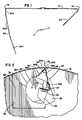
- a preferred embodiment of a printing plate 10 ⁇ incorporating the narrow gap plate mounting apparatus is seen to have a planar body 12 extending between a pair of opposite ends 14 and 16.
- the planar body 12 is made of flexible, rolled steel or the like having a thickness of approximately 0.195 to 0.293 mm (eight to twelve mils).
- the length of the plate 10 ⁇ between ends 14 and 16 is matched to the circumference of the plate cylinder 18 which in this particular embodiment is approximately 512.4 mm (twenty one inches). The length is also matched to that of the cylinder 18 which may vary from approximately 0.61 to 1.52 m (two to five feet).
- the planar, resilient body 12 of the plate 10 ⁇ is mounted by wrapping the body around the surface of the cylinder 18. After being wrapped, the body is held to the cylinder 18 at the opposite ends by means including the narrow gap mounting apparatus including a first tail member 22 and a second, substantially curved tail member 24.
- the first tail member 22 is of planar configuration and extends away from and over the planar body 12 to form an acute angle therewith of approximately forty-four degrees.
- the length of the first tail member 22 is 8.83 mm (0 ⁇ .362 inches), and is joined at the end 14 by a bend having a radius of 0.37 mm (0 ⁇ .0 ⁇ 15 inches).
- the second, curved tail member 24 at the other opposite 16 also extends away from and over the planar body 12 for receipt within the mounting gap, or slot, 20 ⁇ together with the substantially planar tail member 22.
- the objectives are achieved by providing the second tail member with a substantially curved configuration.
- the substantially curved tail 24 has a curved shape which is at least approximately involute.
- the substantially curved shape is achieved by providing a plurality of substantially planar tail member segments 24A, 24B and 24C which are interconnected to approximate the substantially curved shape of the second tail member 24.
- the three planar tail member segments 24A, 24B and 24C are interconnected to approximate an involute shape.
- the lengths of segments 24A, 24B and 24C are 1.66 mm (0 ⁇ .0 ⁇ 68 inches), 9.59 mm (0 ⁇ .393 inches) and 7.76 mm (0 ⁇ .318 inches), respectively.
- the segment 24A forms a right angle with the body 12 and has a bend radius of 0.24 mm (0 ⁇ .0 ⁇ 10 ⁇ inches).
- the middle segment 24B forms an angle of eighty-seven degrees and the distal segment 24C forms an angle of approximately seventy degrees relative to the planar body 12.
- the maximum bend radius for the bends at the beginning of segments 24B and 24C is 0.73 mm (0 ⁇ .0 ⁇ 30 ⁇ inches). While this specific configuration and dimensions for approximating a substantially curved shape for tail 24 has worked successfully, it should be appreciated that variations may be made while still retaining the advantages of the invention.
- the aspect of the plate mounting apparatus associated with the cylinder 18 is seen to include a cavity 26 within the cylinder 18 and in communication with the gap 20 ⁇ which has a substantially curved wall 28.
- the curve of wall 28 is selected to congruently mate with the substantially curved tail member 24.
- the substantially curved wall 28, conforming to the substantially curved tail member 24 of Fig. 1 has three planar segments 28A, 28B and 28C for respectively mating with the curved tail member segments 24A, 24B and 24C to approximate an involute curve.
- the substantially curved tail member 24 snugly fits against the substantially curved wall 28 when the tail member 24 is fully inserted through the gap 20 ⁇ .
- a curved, resilient locking member 30 ⁇ of a rotatable locking mechanism is pressed against the substantially curved tail member 24 at its distal segment 24C to cause it to resiliently press against the curved wall 28 to frictionally hold it within cavity 26.
- the locking mechanism includes a lock rotor 32 mounted for rotation within the cavity about an axis parallel to that of the cylinder 28 and defined by a cylindrical wall 26A of the cavity 26. When rotated in the direction of arrow 33 from the locked position shown in Fig. 2 to an unlocked position, the resilient locking member 30 ⁇ is disengaged from the curved wall 28.
- the resilient locking member 30 ⁇ is releasably attached to the rotor 32 by means of a plurality of screws 35 which are fastened to the underside of a channel 36 provided for that purpose.
- the rotor 32 has a cylindrical wall portion 32A which is rotatably supported within a matching cylindrical wall portion 26A of the cavity 26.
- planar wall 34 which ends at the leading edge 20 ⁇ A of the gap 20 ⁇ and conforms to the first planar tail member 22.
- Planar wall 34 is formed in the side of an insert 38 fitted into an irregularly shaped groove 40 ⁇ in the cylinder 18, while the planar wall segments 28A, 28B and 28C are defined by the walls of the groove 40 ⁇ itself.
- the lock rotor 32 is seen to be slideably removable from the cavity 26 at one end of cylinder 18 and is locked adjacent an adjustment screw 42.
- a worm gear 44 is connected to the lock rotor 32 and engages a threaded section 42A of the adjustment screw 42. Accordingly, when the adjustment screw 42 is rotated in one direction, the worm gear 44 and, thus, the lock rotor 32 and resilient locking arm are rotated in one direction to the unlocked position shown in Fig. 2. When the adjustment screw 42 is rotated in the other direction, the worm gear 44 causes the lock rotor 32 to move to the unlocked position shown in Fig. 4.
- the printing plate body 12 is mounted to the cylinder 18 by first fully inserting the planar tail member 22 into the gap and then wrapping the body 12 around the cylinder 18 in the direction of its normal rotation. After the planar body has been wrapped all the way around the cylinder 18, the curved tail member is fully inserted through the gap 20 ⁇ between the lagging edge 20 ⁇ B of gap 30 ⁇ and the first, planar tail member 22.
- the narrow gap eliminates the need for a locking mechanism which strains the tail member by pulling on it. Accordingly, the locking member 30 ⁇ which only presses against the tail member 24 in a normal direction is employed to hold the curved first member 24 against the wall 28 after they are aligned.
Landscapes
- Engineering & Computer Science (AREA)
- Mechanical Engineering (AREA)
- Supply, Installation And Extraction Of Printed Sheets Or Plates (AREA)
Claims (20)
- Dispositif de montage pour monter une plaque d'impression (10) sur la surface d'un cylindre rotatif (18) d'une presse à imprimer, ladite plaque d'impression (10) ayant un corps plan (12), s'étendant entièrement entre une paire d'extrémités opposées (14, 16), et ledit cylindre (18) ayant un intervalle étroit de montage (20) pour maintenir le corps (12) sur le cylindre (18) auxdites extrémités opposées (14, 16), le dispositif de montage comprenant:- une première pièce de queue (22) à l'une (14) desdites extrémités opposées (14, 16) s'étendant hors du corps plan (12) pour être reçue à l'intérieur de l'intervalle de montage (20);- une seconde pièce de queue, (24) sensiblement incurvée, à l'autre (16) desdites extrémités opposées (14, 16), s'étendant hors du corps plan (12) pour être reçue a l'intérieur de l'intervalle de montage (20) en même temps que la première pièce de queue (22), et- une cavité (26) à l'intérieur du cylindre (18), en communication avec ledit intervalle (20);caractérisé
en ce que ladite seconde pièce de queue (24), sensiblement incurvée, posssède une forme courbée, qui est, au moins approximativement, à développante, en ce qu'une première paroi (28) de ladite cavité (26) est sensiblement courbée pour s'adapter avec ladite seconde pièce de queue (24) , et en ce que des moyens (30, 32) sont prévus pour presser ladite seconde pièce de queue (24) contre ladite première paroi (28) sensiblement courbée, dans une direction qui est sensiblement normale au plan de contact entre elles, afin de réduire sensiblement la contrainte longitudinale et la distorsion de la seconde pièce de queue (24). - Dispositif de montage de la revendication 1, dans lequel la première pièce de queue (22) est sensiblement non courbée.
- Dispositif de montage de la revendication 1, dans lequel ladite seconde pièce de queue (24), sensiblement incurvée, comprend un certain nombre de segments (24A, 24B, 24C) interconnectés pour approcher ladite forme à développante.
- Dispositif de montage de la revendication 3, dans lequel au moins quelques uns desdits segments (24A, 24B, 24C) sont sensiblement non courbés et plans.
- Dispositif de montage de la revendication 1, dans lequel lesdits moyens de pression (30, 32) sont prévus pour maintenir par frottement ladite seconde pièce de queue (24) à l'intérieur de la cavité (26).
- Dispositif de montage de la revendication 2, dans lequel ladite cavité (26) possède une seconde paroi (34), opposée à ladite première paroi (28) sensiblement courbée, qui est sensiblement non courbée pour s'adapter à ladite première pièce de queue (22), sensiblement non courbée.
- Dispositif de montage de la revendication 1, dans lequel les moyens de pression (30, 32) comprennent une pièce de verrouillage (30) pour presser ladite seconde pièce de queue (24), sensiblement courbée, contre la première paroi sensiblement courbée (28).
- Dispositif de montage de la revendication 7, dans lequel lesdits moyens de pression (30, 32) comprennent des moyens (32) pour faire mouvoir ladite pièce de verrouillage (30) entre- une position verrouillée dans laquelle ils obligent la seconde pièce de queue (24), sensiblement courbée, à se presser contre la première paroi sensiblement courbée (28), et- une position déverrouillée dans laquelle la seconde pièce de queue (24) n'est pas pressee contre ladite première paroi (28).
- Dispositif de montage de la revendication 7, dans lequel ladite pièce de verrouillage (30) est élastique.
- Dispositif de montage de la revendication 1, dans lequel ladite première paroi sensiblement courbée (28) est approximativement à développante.
- Dispositif de montage de la revendication 1, dans lequel ladite première paroi sensiblement courbée (28) comprend un certain nombre de segments de paroi (28A, 28B, 28C) interconnectés pour approcher ladite forme sensiblement courbée de ladite première paroi (28).
- Dispositif de montage de la revendication 1, dans lequel lesdites première et seconde parois (28, 34) de ladite cavité (26) sont séparees pour former l'intervalle (20) avec une dimension sensiblement inférieure à 3 mm (0,123 pouce).
- Dispositif de montage de la revendication 1, dans lequel ledit intervalle (20) est choisi pour avoir une dimension inférieure à l'épaisseur du corps de plaque (12) augmentée de 1,22 mm (0,050 pouce).
- Dispositif de montage de la revendication 1, dans lequel ledit intervalle (20) a un bord avant et un bord arrière, et ladite première paroi sensiblement courbée (28) est reliée au bord arrière.
- Dispositif de montage de l'une des revendications précédentes, dans lequel lesdites première et seconde parois (28, 34) de ladite cavité (26), partant de l'intervalle (20), sont conformées par rapport à la première et seconde pièces de queue (22, 24) pour y être adaptées et les recevoir, avec recouvrement, lorsqu'elles sont pleinement insérées dans l'intervalle (20).
- Dispositif de montage des revendications 7 et 15, dans lequel ladite pièce de verrouillage (30) est courbée.
- Dispositif de montage des revendications 8 et 16, dans lequel les moyens de mobilité (32) comprennent des moyens pour faire tourner la pièce de verrouillage (30) vers ladite position verrouillée.
- Dispositif de montage de la revendication 17, dans lequel lesdits moyens de rotation (32) comprennent un engrenage à vis sans fin (44) relié à la pièce de verrouillage (30).
- Procédé de montage d'une plaque d'impression (10) sur un cylindre (18) d'une presse d'impression rotative, comprenant les étapes suivantes:- cintrage des extrémités opposées d'un bloc de plaque d'impression pour former une paire de première et seconde pièces de queue (22, 24) en des extrémités opposées (14, 16) d'un corps plan intermédiaire (12), ladite seconde pièce de queue (24) étant cintrée en forme de courbe;- insertion de la première pièce de queue (22) dans un intervalle de montage (20) du cylindre (18);- amenée du corps intermédiaire (12) autour du cylindre (18);- insertion de la seconde pièce de queue courbée (24) dans l'intervalle (20) entre un bord arrière de l'intervalle (20) et la première pièce de queue (22);caractérisé par le fait que l'étape de cintrage comprend l'étape de cintrage, sensiblement en forme à développante, de la seconde pièce de queue courbée (24) et l'étape de pressage de ladite seconde pièce de queue courbée (24) contre une paroi correspondante courbée (28) d'une cavité (26) en communication avec ledit intervalle (20) dans une direction sensiblement normale à la surface de ladite seconde pièce de queue courbée (24) en un endroit de celle-ci où elle est pressée pour éviter les efforts sur ladite seconde pièce de queue courbée (24)
- Procédé de la revendication 19 dans lequel ladite étape de cintrage de la seconde pièce de queue (24) sensiblement en forme de développante comprend les étapes de réalisation de multiples cintrages successsifs tout au long de la seconde pièce de queue (24) pour approcher ladite forme à développante.
Applications Claiming Priority (2)
| Application Number | Priority Date | Filing Date | Title |
|---|---|---|---|
| US51353890A | 1990-04-24 | 1990-04-24 | |
| US513538 | 1990-04-24 |
Publications (2)
| Publication Number | Publication Date |
|---|---|
| EP0453794A1 EP0453794A1 (fr) | 1991-10-30 |
| EP0453794B1 true EP0453794B1 (fr) | 1994-10-26 |
Family
ID=24043688
Family Applications (1)
| Application Number | Title | Priority Date | Filing Date |
|---|---|---|---|
| EP91104754A Expired - Lifetime EP0453794B1 (fr) | 1990-04-24 | 1991-03-26 | Appareil et procédé pour fixer une plaque d'impression sur un cylindre de fente étroite |
Country Status (4)
| Country | Link |
|---|---|
| EP (1) | EP0453794B1 (fr) |
| JP (1) | JPH04224954A (fr) |
| CA (1) | CA2038809C (fr) |
| DE (2) | DE453794T1 (fr) |
Families Citing this family (4)
| Publication number | Priority date | Publication date | Assignee | Title |
|---|---|---|---|---|
| DE4404758C2 (de) * | 1994-02-15 | 1996-06-27 | Roland Man Druckmasch | Verfahren und Vorrichtung zum Wechseln der Bespannung eines Zylinders einer Rollenrotationsdruckmaschine |
| FR2737149B1 (fr) * | 1995-07-25 | 1997-10-17 | Heidelberg Harris Sa | Dispositif de fixation d'une plaque d'impression sur un cylindre porte-plaque |
| DE19642141C1 (de) * | 1996-10-12 | 1998-06-18 | Koenig & Bauer Albert Ag | Vorrichtung zum Lösen von Platten |
| JP4666707B2 (ja) * | 1999-12-21 | 2011-04-06 | 株式会社ミヤコシ | 版胴における刷版クイックくわえ装置 |
Citations (1)
| Publication number | Priority date | Publication date | Assignee | Title |
|---|---|---|---|---|
| US3408933A (en) * | 1966-03-24 | 1968-11-05 | Miehle Goss Dexter Inc | Continuous take-up clamping arrangement for blanket in printing press |
Family Cites Families (4)
| Publication number | Priority date | Publication date | Assignee | Title |
|---|---|---|---|---|
| US3022728A (en) * | 1959-11-12 | 1962-02-27 | American Type Founders Co Inc | Printing plates and methods and apparatus for forming them |
| DE2334127A1 (de) * | 1973-07-05 | 1975-01-23 | Koenig & Bauer Ag | Vorrichtung zum befestigen und spannen von biegsamen druckplatten |
| US4214530A (en) * | 1978-02-23 | 1980-07-29 | Glanzner Gary C | Metal printing plate |
| DE3470688D1 (en) * | 1983-11-14 | 1988-06-01 | De La Rue Giori Sa | Plate cylinder with a device for affixing gravure printing plates for a web-printing machine |
-
1991
- 1991-03-21 CA CA 2038809 patent/CA2038809C/fr not_active Expired - Fee Related
- 1991-03-26 EP EP91104754A patent/EP0453794B1/fr not_active Expired - Lifetime
- 1991-03-26 DE DE1991104754 patent/DE453794T1/de active Pending
- 1991-03-26 DE DE1991604764 patent/DE69104764T2/de not_active Expired - Fee Related
- 1991-04-23 JP JP9181191A patent/JPH04224954A/ja active Pending
Patent Citations (1)
| Publication number | Priority date | Publication date | Assignee | Title |
|---|---|---|---|---|
| US3408933A (en) * | 1966-03-24 | 1968-11-05 | Miehle Goss Dexter Inc | Continuous take-up clamping arrangement for blanket in printing press |
Also Published As
| Publication number | Publication date |
|---|---|
| EP0453794A1 (fr) | 1991-10-30 |
| CA2038809A1 (fr) | 1991-10-25 |
| JPH04224954A (ja) | 1992-08-14 |
| CA2038809C (fr) | 1998-12-08 |
| DE69104764T2 (de) | 1995-05-04 |
| DE453794T1 (de) | 1992-02-06 |
| DE69104764D1 (de) | 1994-12-01 |
Similar Documents
| Publication | Publication Date | Title |
|---|---|---|
| EP1084842B1 (fr) | Pinces amovibles pour fixer des plaques sur des surfaces externes de tambours | |
| CA2034427C (fr) | Piece souple de plaque d'impression | |
| EP0881074B1 (fr) | Pinces dynamiques pour plaques flexibles | |
| US5685226A (en) | Adaptive clamping mechanism for printing plates | |
| FR2745524A1 (fr) | Dispositif pour fixer un element de revetement sur un cylindre d'un groupe d'impression | |
| US5107763A (en) | Narrow gap plate mounting apparatus and method | |
| CA2148517C (fr) | Appareil et methode servant a assujettir une planche d'impression souple | |
| US4110054A (en) | Clampable plastic gear and the like | |
| EP0453794A1 (fr) | Appareil et procédé pour fixer une plaque d'impression sur un cylindre de fente étroite | |
| US5669306A (en) | Rubber blanket unit fastening device | |
| JP3088477B2 (ja) | 輪転印刷機の版胴に版を緊締するための装置 | |
| US5715752A (en) | Device for drawing a printing plate onto the plate cylinder of a printing machine | |
| US6237492B1 (en) | Cleaning device for a printing press | |
| US5778786A (en) | Plate clamping device for reducing the non-printing region | |
| JP3706808B2 (ja) | ブランケット固定装置及びブランケット固定方法 | |
| US4802413A (en) | Printing plate securing | |
| US4585226A (en) | Resilient document feeding member | |
| JP2970968B2 (ja) | 輪転印刷機の枚葉紙案内胴に胴張りを固定する装置 | |
| EP1172207B1 (fr) | Cylindre de blanchet permettant de faciliter le montage et le démontage d'un blanchet | |
| JPH02193B2 (fr) | ||
| US4641576A (en) | Clamping device for printing plates and printing cloths on printing machines | |
| JPH04226359A (ja) | オフセット印刷機械のプレートシリンダへ印刷プレートを取り付ける方法 | |
| US3724367A (en) | Print drum clamp | |
| JPH06277763A (ja) | 金属部材の曲げ加工装置 | |
| US6374735B1 (en) | Printing plate having interdigitating mounting lugs, a plate cylinder, and method of mounting |
Legal Events
| Date | Code | Title | Description |
|---|---|---|---|
| PUAI | Public reference made under article 153(3) epc to a published international application that has entered the european phase |
Free format text: ORIGINAL CODE: 0009012 |
|
| AK | Designated contracting states |
Kind code of ref document: A1 Designated state(s): DE FR GB |
|
| EL | Fr: translation of claims filed | ||
| 17P | Request for examination filed |
Effective date: 19911205 |
|
| DET | De: translation of patent claims | ||
| 17Q | First examination report despatched |
Effective date: 19930820 |
|
| GRAA | (expected) grant |
Free format text: ORIGINAL CODE: 0009210 |
|
| AK | Designated contracting states |
Kind code of ref document: B1 Designated state(s): DE FR GB |
|
| REF | Corresponds to: |
Ref document number: 69104764 Country of ref document: DE Date of ref document: 19941201 |
|
| ET | Fr: translation filed | ||
| PLBE | No opposition filed within time limit |
Free format text: ORIGINAL CODE: 0009261 |
|
| STAA | Information on the status of an ep patent application or granted ep patent |
Free format text: STATUS: NO OPPOSITION FILED WITHIN TIME LIMIT |
|
| 26N | No opposition filed | ||
| REG | Reference to a national code |
Ref country code: FR Ref legal event code: TP |
|
| REG | Reference to a national code |
Ref country code: GB Ref legal event code: 732E |
|
| REG | Reference to a national code |
Ref country code: GB Ref legal event code: IF02 |
|
| PGFP | Annual fee paid to national office [announced via postgrant information from national office to epo] |
Ref country code: FR Payment date: 20060317 Year of fee payment: 16 |
|
| PGFP | Annual fee paid to national office [announced via postgrant information from national office to epo] |
Ref country code: GB Payment date: 20060329 Year of fee payment: 16 |
|
| PGFP | Annual fee paid to national office [announced via postgrant information from national office to epo] |
Ref country code: DE Payment date: 20060502 Year of fee payment: 16 |
|
| GBPC | Gb: european patent ceased through non-payment of renewal fee |
Effective date: 20070326 |
|
| REG | Reference to a national code |
Ref country code: FR Ref legal event code: ST Effective date: 20071130 |
|
| PG25 | Lapsed in a contracting state [announced via postgrant information from national office to epo] |
Ref country code: DE Free format text: LAPSE BECAUSE OF NON-PAYMENT OF DUE FEES Effective date: 20071002 |
|
| PG25 | Lapsed in a contracting state [announced via postgrant information from national office to epo] |
Ref country code: GB Free format text: LAPSE BECAUSE OF NON-PAYMENT OF DUE FEES Effective date: 20070326 |
|
| PG25 | Lapsed in a contracting state [announced via postgrant information from national office to epo] |
Ref country code: FR Free format text: LAPSE BECAUSE OF NON-PAYMENT OF DUE FEES Effective date: 20070402 |
|
| REG | Reference to a national code |
Ref country code: GB Ref legal event code: 732E Free format text: REGISTERED BETWEEN 20091022 AND 20091028 |
|
| REG | Reference to a national code |
Ref country code: GB Ref legal event code: 732E Free format text: REGISTERED BETWEEN 20091029 AND 20091104 |