EP0453806A1 - Installation pour empiler des pièces constituées d'éléments plats séparés ou de paquets desdits éléments plats - Google Patents
Installation pour empiler des pièces constituées d'éléments plats séparés ou de paquets desdits éléments plats Download PDFInfo
- Publication number
- EP0453806A1 EP0453806A1 EP91104950A EP91104950A EP0453806A1 EP 0453806 A1 EP0453806 A1 EP 0453806A1 EP 91104950 A EP91104950 A EP 91104950A EP 91104950 A EP91104950 A EP 91104950A EP 0453806 A1 EP0453806 A1 EP 0453806A1
- Authority
- EP
- European Patent Office
- Prior art keywords
- stacking
- station
- individual
- individual formats
- roller table
- Prior art date
- Legal status (The legal status is an assumption and is not a legal conclusion. Google has not performed a legal analysis and makes no representation as to the accuracy of the status listed.)
- Granted
Links
Images





Classifications
-
- B—PERFORMING OPERATIONS; TRANSPORTING
- B27—WORKING OR PRESERVING WOOD OR SIMILAR MATERIAL; NAILING OR STAPLING MACHINES IN GENERAL
- B27B—SAWS FOR WOOD OR SIMILAR MATERIAL; COMPONENTS OR ACCESSORIES THEREFOR
- B27B5/00—Sawing machines working with circular or cylindrical saw blades; Components or equipment therefor
- B27B5/02—Sawing machines working with circular or cylindrical saw blades; Components or equipment therefor characterised by a special purpose only
- B27B5/06—Sawing machines working with circular or cylindrical saw blades; Components or equipment therefor characterised by a special purpose only for dividing plates in parts of determined size, e.g. panels
- B27B5/061—Devices having saws perpendicular to each other
-
- B—PERFORMING OPERATIONS; TRANSPORTING
- B27—WORKING OR PRESERVING WOOD OR SIMILAR MATERIAL; NAILING OR STAPLING MACHINES IN GENERAL
- B27B—SAWS FOR WOOD OR SIMILAR MATERIAL; COMPONENTS OR ACCESSORIES THEREFOR
- B27B31/00—Arrangements for conveying, loading, turning, adjusting, or discharging the log or timber, specially designed for saw mills or sawing machines
-
- B—PERFORMING OPERATIONS; TRANSPORTING
- B65—CONVEYING; PACKING; STORING; HANDLING THIN OR FILAMENTARY MATERIAL
- B65G—TRANSPORT OR STORAGE DEVICES, e.g. CONVEYORS FOR LOADING OR TIPPING, SHOP CONVEYOR SYSTEMS OR PNEUMATIC TUBE CONVEYORS
- B65G57/00—Stacking of articles
- B65G57/02—Stacking of articles by adding to the top of the stack
- B65G57/03—Stacking of articles by adding to the top of the stack from above
- B65G57/035—Stacking of articles by adding to the top of the stack from above with a stepwise downward movement of the stack
Definitions
- the invention relates to a device for stacking individual formats produced from divided, plate-shaped individual workpieces or plate packs, with the features of the preamble of patent claim 1.
- the program-controlled stacking trolley which can be moved above the stacking stations, can either be supplied with a split image (colorfully divided workpiece plate or a correspondingly split plate package) leaving a plate sizing system as a whole or only one crosswise divided strip of such a split image either as a whole or its individual formats.
- Strips, or the individual formats forming them, or the entire split image are then conveyed to one or more stacking stations for stacking by means of the stacking carriage.
- the strip consisting of several individual formats or its individual individual formats is fed to a stacking station selected according to the program, whereupon the stacking device comes into operation and stores this or its individual formats there.
- the destacking device comes into operation during a transport movement of the destacking trolley into several selected stacking stations, one of the transversely divided strips of the recorded split image being stacked by the stacking trolley in successively approached stacking stations.
- the destacking device on the destacking trolley has a controllable squeegee which, for the individual placement of transversely divided strips or, in the case of an overlapping split image, shifts the same by the width of such strips against the direction of movement of the destacking trolley. Accordingly, only one of the strips of a split image is pushed down from the stacking trolley at the corresponding stacking stations.
- This device works time-consuming, so that a continuous passage of individual plates or plate packages to be divided through plate dividing systems is only possible to a limited extent.
- the invention has for its object to improve a device in an embodiment according to the preamble of claim 1 so that it works with high cycle power and thus enables a continuous plate run through an upstream plate sizing system.
- individual formats can be stacked at short notice in different stacking stations from the layout of individual workpiece plates or plate packs, so that plate stacks formed from the same individual formats are produced when individual workpiece plates or plate packs are processed according to the same cutting plan. It should be possible to form two or possibly several individual stacks of different, identical-format individual formats at the same time in a stacking station, provided the individual formats are of correspondingly small dimensions.
- the stacking trolleys provided according to the invention move along an endless guideway, so that they have to be provided in rapid succession for the acceptance of one or possibly several transversely divided plate or package strips, which are always controlled in one direction only.
- the device according to the invention is advantageously linked to a panel dividing system having a longitudinal saw and a cross saw.
- a separating device must be interposed between the two in order to separate the adjacent formats of adjacent, transversely divided strips of a split image before they are transferred to the device according to the invention in the longitudinal direction of the strip.
- two or possibly several strips of a split image lying next to one another can also be separated at the same time, such that, as already explained above, two or more individual formats lying next to one another are simultaneously fed to a stacking trolley and accordingly also in the ones selected for stacking Stacking stations are stacked together side by side.
- the guideway can run according to claims 2 or 3. In the latter case, there is an advantageous construction according to claim 4.
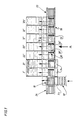
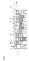
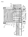
- the stacking device has, for example, stacking stations I-VII.
- an input station 10 In front of the stacking station I there is an input station 10, to which 12 individual formats of an individual, transversely divided longitudinal plate strip are fed, for example via a separating device 12.
- Each stacking station I - VII and the input station 10 are assigned a transfer device I '- VII', which are designed, for example, as roller conveyors.
- the row of stacking stations I-VII adjoining one another preferably extends perpendicular to the conveying direction of the separating device 12.
- Each stacking station I - VII is equipped with a lifting table 14 which, after each transfer of an individual format or a stack of packages 16 (individual format of a plate package), is lowered by an amount corresponding to the height of these parts, so that the individual format at the top of the deposited or formed Stack is located in all stacking stations I - VII on the same level for taking over a further individual format or stack of packages.
- a lifting table 14 which, after each transfer of an individual format or a stack of packages 16 (individual format of a plate package), is lowered by an amount corresponding to the height of these parts, so that the individual format at the top of the deposited or formed Stack is located in all stacking stations I - VII on the same level for taking over a further individual format or stack of packages.
- a transport device 18 is arranged above the stacking stations I-VII, with the aid of which program-controlled stacking takes place in the individual stacking stations I-VII. It has a number of stacking trolleys 20, which is preferably three more than the number of stacking stations I-VII.
- the stacking trolleys 20 move in two superposed levels aa and bb along the row of stacking stations I - VII in such a way that they pass out of their conveying level in a lifting station 22 after passing the last stacking station VII aa be raised to the return level bb. If they have passed the input station 10 in this level bb, they run into a further lifting station 24, in which they are lowered into the conveyor level aa before they are fed back to the input station 10.
- Each stacking station I - VII is assigned a stacking device, designated as a whole by 26, which can be controlled via a control program which is coordinated with the distribution program of an upstream plate dividing system in such a way that individual formats or stacked packages which are conveyed by means of a stacking carriage 20 are stacked in the stacking station provided for stacking them be pushed down by the stacking trolley 20.
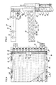
- the stacking trolleys 20 are U-shaped in side view, their U-legs 28 and 30 extending horizontally.
- the U-leg 28 receiving a single format or, as shown in FIG. 3, a stack of parcels 32 forms a stacking rake, the individual rake tines of which are denoted by 34 in FIG. These are angular in shape, the vertical tine section 34 'of which is fastened to an upper transverse yoke 36. While the lower edge 38 of the tines 34 runs essentially horizontally, the upper edge 40 of the parcel 32 falls slightly obliquely in the direction of the free tine end in order to push off the stack of packs 32, for example.
- the transverse yoke 36 carries at both ends the upper U-leg 30 of the stacking trolley 20 supporting rails 42 and 44, in each of which two pairs of guide rollers 46 and 48 are freely rotatably mounted.
- Each stacking carriage 20 is equipped with its own drive device 52, which is seated on the transverse yoke 36. It has a program-controlled electric motor 54 through which a drive shaft 56 can be driven. This extends in each case into the region of the mounting rails 42 and 44, a pinion 58 and 60 respectively being seated in a rotationally fixed manner on their shaft ends.
- the stacking device 26 assigned to the stacking trolleys 20 in the stacking stations I-VII has a scraper comb 26 ', the comb teeth 62 of which, as indicated by the double arrow 64, between the vertically extending tine sections 34' of the stacking trolleys 20 from a lower release position into a position shown in FIG 3 shown, upper stripping position are controllable.
- the scraper comb 26 ' is actuated with the aid of an actuator which can be controlled as a function of the program, for example in the form of a double-acting cylinder 66, the piston rod 68 of which is mounted on the frame at 70.
- the pairs of rollers 46, 48 of each support rail 28, 30 roll on lateral, horizontal guide rails 72 and 74 (FIG. 1), of which only one is shown in FIG. 7.
- a toothed rack 76 which engages with one of the toothed pinions 58 and 60, respectively.
- the stacking trolleys 20 are therefore driven when the drive shaft 56 rotates.
- the two lifting stations 22 and 24 are structurally identical. As an extension of the horizontal guide rails 72 and 74, they each have two guide rail sections 72 'and 74' (FIG. 6), both of which also carry a rack section 76 '(Fig. 5).
- the guide rail sections 72 'and 74' are each held with their end regions on the underside of a crossbar 78 or 80, for which purpose they are fastened to spacers 82 and 84 connected to them in such a way that the stacking carriages 20 underneath each of these crossbars 78 and 80, respectively. 80 past and into the lifting station 24 or extend from the lifting station 22.
- Each crossbar 78 and 80 is supported in its end regions on two lifting devices 94, preferably accommodated in frame columns 86, 88 or 90, 92, which are preferably each formed by a double-acting cylinder unit, the cylinders 96 of which receive the guide rail sections 72 'and 74' and whose piston rod 98 is pivotally supported at 100 in the frame columns 86-92.
- the lower starting position (conveying plane a-a) of the guide rail sections 72 'and 74' is indicated by dash-dotted lines in FIG. 5.
- the facility works as follows: It is assumed that the individual formats of a split image (workpiece plate divided according to a cutting plan) are to be stacked in the device in such a way that individual formats having the same format are stacked in their stacking stations I - VII.
- the split image leaves the plate dividing system in question in such a way that mutually adjacent, transversely divided longitudinal strips abut one another.
- the prerequisite for the desired stacking of individual formats in the same stacking station is that the individual formats of a longitudinal strip of the split image are fed individually to the input station 10. For this reason, it is necessary, as already mentioned, to interpose the separating device 12 between the input station 10 and the plate dividing system (see FIG. 1).
- a stacking carriage 20 is already provided in the input device 10, onto which an incoming individual format is deposited by lowering.
- the input station 10 is equipped, for example, with friction rollers 35 which engage between the tines 34 of the stacking carriage 20 and protrude on their upper side and which are lowered as soon as the individual format is in the storage position above the tines 34 of the stacking carriage 20.
- the drive device 52 of this stacking carriage 20 is now controlled via a control program, which now travels continuously in the conveyor plane aa over the individual stacking stations I VII.
- the stacking device 26 of the stacking station into which the individual format picked up by the stacking trolley 20 is to be stacked is made according to the work program Arrival of the stacking trolley 20 in its stripping position is controlled upwards (see FIG. 3), the individual format running against its stripping comb 26 'and stripped off by the stacking trolley 20 because of this and is placed on the lifting table 14.
- the stacking station 20 After the emptied stacking trolley 20 has been moved into the lifting station 22, the stacking station 20 functions, feeds the stacking trolley 20 into the return plane bb, after which its drive device 52 is reversed, the stacking trolley 20 thus moves towards the lifting station 24, in which it is lowered again into the conveying plane aa and then transported to the input station by reversing the drive device 52 again and made available there for taking over a further individual format.
- a stacking trolley 20 After a stacking trolley 20 is preferably provided for all stations, individual formats or stacked stacks can be continuously transferred to a stacking trolley 20 in the input station 10, the stacking devices 26 of the various stacking stations I being used to store the individual formats or package stacks in accordance with the sequence of the sawing program of the panel sizing system - VII controlled according to the program.
- the lifting tables 14 of the input station 10 and of the two following stacking stations I and II are larger than the lifting tables 14 of the other stacking stations III-VII, so that they protrude beyond the front of the device. This is provided so that in these two stacking stations I and II individual formats of particularly long lengths can be stacked cheaply.
- a collecting station designated as a whole by 104, is interposed between the separating device 12 and the input station 10, which in turn is followed by a waiting station, designated as a whole by 106.
- this collecting station 104 With the aid of this collecting station 104, it is possible to align individual individual formats or stacks of packages precisely before they are fed into the input station 10. In addition, it is possible to collect individual formats or stacks of packages in a predetermined number before they are fed to the input station 10 and then to feed them to the input station 10 in a precisely aligned manner in one operation.
- the waiting station 106 would not yet be required for this. In this case, their arrangement could be dispensed with. The purpose of the waiting station 106 is therefore not yet discussed at first.
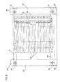
- the collecting station 104 has a roller table 108, the rollers of which form friction rollers 112 mounted in axes 110 arranged transversely to the conveying direction.
- support rails 114 extend across the entire table width.
- Support rails 114 and friction rollers 112, which are no longer shown, are vertically adjustable relative to one another, such that the support rails are located below the support plane defined by the friction rollers 112 for pushing up or down individual formats or stacked packages.
- the support rails 118 are preferably designed to be raised and lowered.
- the roller table 108 is assigned an alignment device, designated as a whole by 116, with the aid of which individual formats or stack of packages can be precisely aligned before they are fed to the input station 10.
- the alignment device 116 has an alignment stop 118 which extends over the entire length of the table in the conveying direction and a conveyor stop 120 which extends perpendicularly thereto and is arranged on the side facing the input station and extends essentially over the entire table width.
- the latter can be controlled programmatically up and down.
- lifting devices for example pneumatic lifting cylinders 122 and 124, which can be steered upwards from the stop position shown in FIG. 10 into a release position in order to be able to run the parts lying on the roller table 108 into the input station 10.
- the alignment stop 118 is suspended on piston rods 126 by preferably pneumatic lifting cylinders 128 and 130, which in turn are seated on a carriage 132, which in turn is slidably guided on two upper, horizontal guide rails 134 and 136.
- the carriage 132 is equipped with two pairs of guide rollers 138 and 140 for each guide rail 134 and 136, of which one pair rolls on the top and the other pair on the underside of the respective guide rail 134 and 136.
- the carriage 132 which is not shown, can be adjusted in a program-controlled manner by means of a drive device, for which purpose, for example, at least the guide rollers 138 or 140 are in engagement with a toothed rack.
- the collecting device 104 works without the waiting station 106 linked to it as follows: It is assumed that the input station 10 is to be supplied with a large number of individual formats 142 in an exactly aligned manner. It is further assumed that the length of the individual formats 142 corresponds, for example, to approximately half the length of the roller table 108, so that in each case two individual formats 142 can be accommodated one behind the other in the conveying direction by the roller table 108.
- the alignment stop 118 and the conveyor stop 120 are to be lowered into their stop position shown in FIG. 10.
- the mounting rails 114 remain in their lower starting position.
- the friction rollers 12 'of the separating device 12 are positioned obliquely with respect to a side stop 144 in such a way that individually supplied individual formats 142 already arrive at the roller table 108 in a longitudinal direction.
- the friction rollers 112 continue to convey them on the roller table 108 until the single format 142 viewed in the direction of conveyance comes to rest against the conveyor stop 120.
- the mounting rails are steered upwards and accommodate both individual formats 142 at the same time.
- the carriage 132 comes into operation and, via the aligning stop 118, shifts both individual formats 142 parallel to itself in the direction of the waiting station 106 by a distance which is slightly larger than the width of the individual formats 142.
- the carriage 132 then moves into the position shown in FIG 9 starting position shown back, the mounting rails 114 are lowered and a further pair of individual formats 142 is conveyed onto the roller table 108.
- alignment stop 118 and mounting rails 114 then takes place again until, for example, three pairs of individual formats 142 are received by the roller table 108, the mounting rails 114 remaining in their upper position after receiving the two last delivered individual formats 142, the alignment stop 118 in its upper starting position is raised and the carriage 132 is steered towards the waiting station 106 by a distance such that the alignment stop 118 can then be lowered behind the two individual formats 142 delivered first or adjacent to the waiting station 106.
- the carriage 132 is then reversed in the opposite direction, with the existing pairs of individual formats 142 or, as can be seen from FIG. 10, corresponding pairs of package stacks 142 ′ being pushed exactly against one another into a transfer position via the alignment stop 118.
- the friction rollers 112 After lowering the support rails 114 and lifting the conveyor stop 120, the friction rollers 112 then come into operation and feed the individual formats 142 or package stacks 142 'together via an intermediate roller table 146 to the input station 10, from which they are transported together to a stacking station I-VII selected according to the program will.
- the waiting station 106 does the following: As a rule, a split image obtained behind a plate sizing system contains a number of individual formats 142 or packet stacks 142 ', for example 6 pieces, each of which can be aligned, for example, half on the roller table 108. In this case, the waiting station 106 is not required.
- split images may also occur, which may contain a total of, for example, seven or more individual formats 142 or packet stacks 142 '. In this case there is e.g. a single format 142 or stack of packages 142 ′ which can no longer be accommodated with others on the roller table 108 or is to be fed to the input station 10 together with them.
- Such surplus individual formats 142 or package stacks 142 ′ can then be fed to the waiting station 106 with the aid of the alignment stop 118, in which as many can be accumulated as are required for a complete loading of the input station 10.
- a collection level in the waiting station 106 could already suffice for this.
- the waiting station 106 is so that such temporarily stored, surplus individual formats 142 or package stacks 142 'can be supplied quickly after the division of an intended number of workpiece plates on a plate dividing system and stacking of the individual formats 142 or package stacks 142' of the division images produced from these workpiece plates equipped with several storage levels arranged one above the other (FIG. 11), which are located on lifting platforms 146.
- lifting platforms 146 which are jointly adjustable in height in a guide frame 148 by means of a drive device 150 and individually adjustable in the plane of the roller table 108 of the collecting station 104.
- the storage level of this lifting platform 146 is preferably each formed by the upper run 152 of an endless, horizontal belt conveyor 154, the drive of which is program-controlled in both directions.
- lifting capacity of these lifting platforms 146 corresponds at least to that of the roller table 108.
- a different design of the lifting platforms 146 and the waiting station 148 is of course also conceivable.
- a parking station 156 can also be assigned to the input station 10 of the stacking device opposite the collecting station 104. It has the task of individual formats 142 or package stacks 142 'individually, or by to collect the collecting station 104, that is to say to store several of them at the same time, in the event that the stacking station to be selected in accordance with the program for their stacking should not be receptive or should just be emptied.
- the construction of the parking station 156 expediently corresponds to that of the waiting station 106 explained, an intermediate table 158 having friction rollers also being able to be provided between the input station 10 and the parking station 156.
- Collection station 104, waiting station 106 and parking station 156 are also considered worthy of protection in themselves.
Landscapes
- Life Sciences & Earth Sciences (AREA)
- Engineering & Computer Science (AREA)
- Mechanical Engineering (AREA)
- Wood Science & Technology (AREA)
- Forests & Forestry (AREA)
- Pile Receivers (AREA)
- Attitude Control For Articles On Conveyors (AREA)
- Stacking Of Articles And Auxiliary Devices (AREA)
- Pallets (AREA)
- Specific Conveyance Elements (AREA)
Priority Applications (2)
| Application Number | Priority Date | Filing Date | Title |
|---|---|---|---|
| AT91104950T ATE93488T1 (de) | 1990-04-23 | 1991-03-28 | Einrichtung zum abstapeln von aus aufgeteilten, plattenfoermigen einzelwerkstuecken oder plattenpaketen hergestellten einzelformaten. |
| EP93101055A EP0540505B1 (fr) | 1990-04-23 | 1991-03-28 | Installation pour empiler des pièces à usiner partagées en forme de plaques individuelles ou en paquets |
Applications Claiming Priority (2)
| Application Number | Priority Date | Filing Date | Title |
|---|---|---|---|
| DE4012840A DE4012840A1 (de) | 1990-04-23 | 1990-04-23 | Einrichtung zum abstapeln von aus aufgeteilten, plattenfoermigen einzelwerkstuecken oder plattenpaketen hergestellten einzelformaten |
| DE4012840 | 1990-04-23 |
Related Child Applications (1)
| Application Number | Title | Priority Date | Filing Date |
|---|---|---|---|
| EP93101055.7 Division-Into | 1993-01-25 |
Publications (2)
| Publication Number | Publication Date |
|---|---|
| EP0453806A1 true EP0453806A1 (fr) | 1991-10-30 |
| EP0453806B1 EP0453806B1 (fr) | 1993-08-25 |
Family
ID=6404869
Family Applications (2)
| Application Number | Title | Priority Date | Filing Date |
|---|---|---|---|
| EP91104950A Expired - Lifetime EP0453806B1 (fr) | 1990-04-23 | 1991-03-28 | Installation pour empiler des pièces constituées d'éléments plats séparés ou de paquets desdits éléments plats |
| EP93101055A Expired - Lifetime EP0540505B1 (fr) | 1990-04-23 | 1991-03-28 | Installation pour empiler des pièces à usiner partagées en forme de plaques individuelles ou en paquets |
Family Applications After (1)
| Application Number | Title | Priority Date | Filing Date |
|---|---|---|---|
| EP93101055A Expired - Lifetime EP0540505B1 (fr) | 1990-04-23 | 1991-03-28 | Installation pour empiler des pièces à usiner partagées en forme de plaques individuelles ou en paquets |
Country Status (3)
| Country | Link |
|---|---|
| EP (2) | EP0453806B1 (fr) |
| AT (2) | ATE108412T1 (fr) |
| DE (3) | DE4012840A1 (fr) |
Cited By (6)
| Publication number | Priority date | Publication date | Assignee | Title |
|---|---|---|---|---|
| GB2262729A (en) * | 1991-12-26 | 1993-06-30 | Tadao Uno | Device for piling bundles of sheets |
| FR2692567A1 (fr) * | 1992-06-23 | 1993-12-24 | Uno Tadao | Système d'empilement de paquets de feuilles en trois dimensions. |
| GB2268147A (en) * | 1992-06-23 | 1994-01-05 | Tadao Uno | Sheet block stacking system |
| ES2078841A2 (es) * | 1992-06-23 | 1995-12-16 | Tadao Uno | Sistema de apilamiento tridimensional de paquetes de hojas. |
| EP1746057A1 (fr) * | 2005-07-19 | 2007-01-24 | Müller Martini Holding AG | Méthode et dispositif pour la formation de paquets d' objets empilables |
| WO2018210928A1 (fr) * | 2017-05-17 | 2018-11-22 | Homag Plattenaufteiltechnik Gmbh | Dispositif de désempilage, système de traitement de pièces et procédé destiné à faire fonctionner un dispositif de désempilage |
Families Citing this family (5)
| Publication number | Priority date | Publication date | Assignee | Title |
|---|---|---|---|---|
| AT398746B (de) * | 1992-06-25 | 1995-01-25 | Schelling & Co | Einrichtung zum zusammenstellen von auf einer plattenaufteilanlage durch längs- und querschnitte aus plattenförmigen werkstücken gewonnenen formatzuschnitten zu stapelbildern |
| DE4337739C1 (de) * | 1993-11-05 | 1994-08-25 | Klessmann Ima Norte Maschfab | Bearbeitungszentrum zum spangebenden Bearbeiten von plattenförmigen Werkstücken |
| DE4433644B4 (de) * | 1994-09-21 | 2005-03-03 | Heidelberger Druckmaschinen Ag | Verfahren und Vorrichtung zur Führung eines Bogens |
| CN111908140A (zh) * | 2020-09-25 | 2020-11-10 | 宁波艾思科汽车音响通讯有限公司 | 一种扬声器自动插焊片设备的小车自动堆码装置 |
| CN112607375B (zh) * | 2020-12-11 | 2022-10-11 | 豪德机械(上海)有限公司 | 一种多尺寸地板的堆垛设备 |
Citations (3)
| Publication number | Priority date | Publication date | Assignee | Title |
|---|---|---|---|---|
| AT333663B (de) * | 1974-03-20 | 1976-12-10 | Schelling & Co | Einrichtung zur aufnahme und weitergabe bzw. zum abstapeln plattenformiger werkstucke |
| AT343538B (de) * | 1976-10-04 | 1978-06-12 | Schelling & Co | Plattenaufteil- und sortieranlage mit mindestens einer stapeleinrichtung |
| AT351445B (de) * | 1976-01-09 | 1979-07-25 | Wehner Maschf | Vorrichtung zum transportieren und abstapeln von plattenfoermigem material |
Family Cites Families (9)
| Publication number | Priority date | Publication date | Assignee | Title |
|---|---|---|---|---|
| DE1894277U (de) * | 1964-03-03 | 1964-06-04 | Helmut Ulrich | Automatische stapelvorrichtung zum stapeln von keramischen wandplatten. |
| DE2501012A1 (de) * | 1975-01-11 | 1976-07-15 | Rudolf Grenzebach | Verfahren und vorrichtung zum aufeinandersetzen von stapeln |
| DE2523183A1 (de) * | 1975-05-26 | 1976-12-02 | Wehner Maschf | Verfahren und einrichtung zum separieren und abstapeln von platten-teilpaketen, vorzugsweise im zusammenhang mit einer plattenaufteilsaege |
| DE7923583U1 (de) * | 1979-08-18 | 1981-02-05 | Weniger & Co Inh. Heinz Weniger, 4800 Bielefeld | Vorrichtung zum stapeln von platten |
| DE3031648A1 (de) * | 1980-08-22 | 1982-07-15 | Weniger & Co, Inh. Doris Weniger, 4800 Bielefeld | Vorrichtung zum foerdern und stapeln von platten |
| AT377495B (de) | 1981-06-23 | 1985-03-25 | Schelling & Co | Einrichtung zum verteilen und stapeln von zuschnitten bei buntaufteilanlagen |
| IT1202088B (it) * | 1985-06-07 | 1989-02-02 | Giben Impianti Spa | Impianto per l'impilamento di pacchi di pannelli di dimensione diversa, prodotti da un impianto di sezionatura e per ordinare le pile una vicino all'altra, onde formare degli agglomerati parallelepipediformi che vengono poi trasferiti in una stazione di scarico previa eventuale disposizione su di un pallet o su altro mezzo di appoggio e di protezione |
| FR2588844B1 (fr) * | 1985-10-21 | 1988-04-29 | Hotchkiss Brandt Sogeme | Palettiseur pour charges diversifiees |
| DE3734655A1 (de) * | 1986-10-23 | 1988-04-28 | Erwin Jenkner | Anlage zum aufteilen von platten und foerdern und stapeln der zuschnitte |
-
1990
- 1990-04-23 DE DE4012840A patent/DE4012840A1/de not_active Withdrawn
-
1991
- 1991-03-28 DE DE91104950T patent/DE59100314D1/de not_active Expired - Fee Related
- 1991-03-28 AT AT93101055T patent/ATE108412T1/de not_active IP Right Cessation
- 1991-03-28 DE DE59102195T patent/DE59102195D1/de not_active Expired - Fee Related
- 1991-03-28 EP EP91104950A patent/EP0453806B1/fr not_active Expired - Lifetime
- 1991-03-28 AT AT91104950T patent/ATE93488T1/de not_active IP Right Cessation
- 1991-03-28 EP EP93101055A patent/EP0540505B1/fr not_active Expired - Lifetime
Patent Citations (3)
| Publication number | Priority date | Publication date | Assignee | Title |
|---|---|---|---|---|
| AT333663B (de) * | 1974-03-20 | 1976-12-10 | Schelling & Co | Einrichtung zur aufnahme und weitergabe bzw. zum abstapeln plattenformiger werkstucke |
| AT351445B (de) * | 1976-01-09 | 1979-07-25 | Wehner Maschf | Vorrichtung zum transportieren und abstapeln von plattenfoermigem material |
| AT343538B (de) * | 1976-10-04 | 1978-06-12 | Schelling & Co | Plattenaufteil- und sortieranlage mit mindestens einer stapeleinrichtung |
Cited By (14)
| Publication number | Priority date | Publication date | Assignee | Title |
|---|---|---|---|---|
| GB2262729A (en) * | 1991-12-26 | 1993-06-30 | Tadao Uno | Device for piling bundles of sheets |
| GB2262729B (en) * | 1991-12-26 | 1996-04-03 | Tadao Uno | Device for piling bundles of sheets |
| NL9300007A (nl) * | 1992-06-23 | 1994-01-17 | Uno Tadao | Drie-dimensioneel opstapelsysteem voor blokken vellen. |
| GB2268147A (en) * | 1992-06-23 | 1994-01-05 | Tadao Uno | Sheet block stacking system |
| AU661357B2 (en) * | 1992-06-23 | 1995-07-20 | Tadao Uno | Block formation unit and sheet block stacking system |
| ES2078841A2 (es) * | 1992-06-23 | 1995-12-16 | Tadao Uno | Sistema de apilamiento tridimensional de paquetes de hojas. |
| FR2692567A1 (fr) * | 1992-06-23 | 1993-12-24 | Uno Tadao | Système d'empilement de paquets de feuilles en trois dimensions. |
| GB2268147B (en) * | 1992-06-23 | 1996-04-17 | Tadao Uno | Three-dimensional sheet block stacking system |
| DE4320863B4 (de) * | 1992-06-23 | 2008-09-11 | Uno, Tadao, Chigasaki | Anlage in einem Paketbildungszentrum zum Aufeinanderlegen mehrerer Blattbündel oder ähnlicher flächiger Einheiten, z.B. Bücher, zu Paketen |
| EP1746057A1 (fr) * | 2005-07-19 | 2007-01-24 | Müller Martini Holding AG | Méthode et dispositif pour la formation de paquets d' objets empilables |
| US7699578B2 (en) | 2005-07-19 | 2010-04-20 | Müller Martini Holding AG | Method and device for forming bundles of stackable objects |
| WO2018210928A1 (fr) * | 2017-05-17 | 2018-11-22 | Homag Plattenaufteiltechnik Gmbh | Dispositif de désempilage, système de traitement de pièces et procédé destiné à faire fonctionner un dispositif de désempilage |
| CN110636928A (zh) * | 2017-05-17 | 2019-12-31 | 豪迈面板分割科技有限公司 | 堆放装置、工件加工设备以及用于运行堆放装置的方法 |
| CN110636928B (zh) * | 2017-05-17 | 2022-03-08 | 豪迈面板分割科技有限公司 | 堆放装置、工件加工设备以及用于运行堆放装置的方法 |
Also Published As
| Publication number | Publication date |
|---|---|
| ATE93488T1 (de) | 1993-09-15 |
| EP0540505A2 (fr) | 1993-05-05 |
| ATE108412T1 (de) | 1994-07-15 |
| DE4012840A1 (de) | 1991-10-24 |
| EP0540505A3 (en) | 1993-06-09 |
| DE59100314D1 (de) | 1993-09-30 |
| EP0540505B1 (fr) | 1994-07-13 |
| EP0453806B1 (fr) | 1993-08-25 |
| DE59102195D1 (de) | 1994-08-18 |
Similar Documents
| Publication | Publication Date | Title |
|---|---|---|
| EP0247408B1 (fr) | Dispositif de distribution et de triage pour plaques | |
| EP0623542B1 (fr) | Dispositif pour empiler un chant de feuilles imprimées | |
| DE2702725C2 (de) | Plattenaufteil-, sortier- und -stapelanlage mit mindestens einer Stapeleinrichtung | |
| DE2911457A1 (de) | Stapelvorrichtung | |
| DE3038058A1 (de) | Einrichtung zum aufstapeln von flachen gegenstaenden,insbesondere von faltschachtel-zuschnitten | |
| EP0540505B1 (fr) | Installation pour empiler des pièces à usiner partagées en forme de plaques individuelles ou en paquets | |
| DE2702724C2 (de) | Einrichtung zum Sortieren und Ablegen von Zuschnitten bei Plattenaufteilanlagen | |
| DE2355143B2 (de) | Paletten-Umsetzvorrichtung | |
| AT405821B (de) | Einrichtung zum sortieren und stapeln | |
| DE2935263A1 (de) | Automatische buchstapelmaschine | |
| DE2106091C3 (de) | Vorrichtung zum verschachtelten, lageweisen Stapeln von profiliertem Walzgut | |
| AT402197B (de) | Sortier- und stapelanlage für plattenaufteileinrichtungen | |
| AT377495B (de) | Einrichtung zum verteilen und stapeln von zuschnitten bei buntaufteilanlagen | |
| DE4315133B4 (de) | Einrichtung bei Buntaufteilanlagen | |
| AT396766B (de) | Einrichtung zum buntaufteilen von plattenförmigen werkstücken | |
| DE4209952A1 (de) | Einrichtung bei buntaufteilanlagen | |
| DE4314600B4 (de) | Vorrichtung zur lageweisen Stapelung von gruppierten Gegenständen | |
| AT403159B (de) | Sortier- und stapelanlage für plattenaufteileinrichtungen | |
| AT410541B (de) | Vorrichtung zum stapeln von formatzuschnitten mit einem verfahrbaren gabelwagen | |
| AT410660B (de) | Stapelgerät | |
| AT405508B (de) | Sortier- und stapeleinrichtung für plattenaufteilanlagen | |
| AT398745B (de) | Einrichtung zum sortieren von unterschiedlichen, auf buntaufteilanlagen aus plattenförmigen werkstücken durch längs- und querschnitte gewonnene formatzuschnitte | |
| DE3734655A1 (de) | Anlage zum aufteilen von platten und foerdern und stapeln der zuschnitte | |
| DE3715173A1 (de) | Plattenaufteil- und -sortieranlage | |
| DE3616921C2 (fr) |
Legal Events
| Date | Code | Title | Description |
|---|---|---|---|
| PUAI | Public reference made under article 153(3) epc to a published international application that has entered the european phase |
Free format text: ORIGINAL CODE: 0009012 |
|
| AK | Designated contracting states |
Kind code of ref document: A1 Designated state(s): AT BE CH DE ES FR GB IT LI NL SE |
|
| 17P | Request for examination filed |
Effective date: 19911010 |
|
| 17Q | First examination report despatched |
Effective date: 19930209 |
|
| GRAA | (expected) grant |
Free format text: ORIGINAL CODE: 0009210 |
|
| AK | Designated contracting states |
Kind code of ref document: B1 Designated state(s): AT BE CH DE ES FR GB IT LI NL SE |
|
| PG25 | Lapsed in a contracting state [announced via postgrant information from national office to epo] |
Ref country code: IT Free format text: LAPSE BECAUSE OF FAILURE TO SUBMIT A TRANSLATION OF THE DESCRIPTION OR TO PAY THE FEE WITHIN THE PRE;WARNING: LAPSES OF ITALIAN PATENTS WITH EFFECTIVE DATE BEFORE 2007 MAY HAVE OCCURRED AT ANY TIME BEFORE 2007. THE CORRECT EFFECTIVE DATE MAY BE DIFFERENT FROM THE ONE RECORDED.SCRIBED TIME-LIMIT Effective date: 19930825 Ref country code: SE Effective date: 19930825 Ref country code: NL Effective date: 19930825 Ref country code: ES Free format text: THE PATENT HAS BEEN ANNULLED BY A DECISION OF A NATIONAL AUTHORITY Effective date: 19930825 Ref country code: GB Effective date: 19930825 Ref country code: BE Effective date: 19930825 |
|
| REF | Corresponds to: |
Ref document number: 93488 Country of ref document: AT Date of ref document: 19930915 Kind code of ref document: T |
|
| XX | Miscellaneous (additional remarks) |
Free format text: TEILANMELDUNG 93101055.7 EINGEREICHT AM 28/03/91. |
|
| REF | Corresponds to: |
Ref document number: 59100314 Country of ref document: DE Date of ref document: 19930930 |
|
| ET | Fr: translation filed | ||
| PGFP | Annual fee paid to national office [announced via postgrant information from national office to epo] |
Ref country code: FR Payment date: 19940209 Year of fee payment: 4 |
|
| PGFP | Annual fee paid to national office [announced via postgrant information from national office to epo] |
Ref country code: CH Payment date: 19940211 Year of fee payment: 4 |
|
| PGFP | Annual fee paid to national office [announced via postgrant information from national office to epo] |
Ref country code: AT Payment date: 19940214 Year of fee payment: 4 |
|
| NLV1 | Nl: lapsed or annulled due to failure to fulfill the requirements of art. 29p and 29m of the patents act | ||
| GBV | Gb: ep patent (uk) treated as always having been void in accordance with gb section 77(7)/1977 [no translation filed] |
Effective date: 19930825 |
|
| PGFP | Annual fee paid to national office [announced via postgrant information from national office to epo] |
Ref country code: DE Payment date: 19940517 Year of fee payment: 4 |
|
| PLBE | No opposition filed within time limit |
Free format text: ORIGINAL CODE: 0009261 |
|
| STAA | Information on the status of an ep patent application or granted ep patent |
Free format text: STATUS: NO OPPOSITION FILED WITHIN TIME LIMIT |
|
| 26N | No opposition filed | ||
| PG25 | Lapsed in a contracting state [announced via postgrant information from national office to epo] |
Ref country code: AT Effective date: 19950328 |
|
| PG25 | Lapsed in a contracting state [announced via postgrant information from national office to epo] |
Ref country code: LI Effective date: 19950331 Ref country code: CH Effective date: 19950331 |
|
| PG25 | Lapsed in a contracting state [announced via postgrant information from national office to epo] |
Ref country code: FR Free format text: LAPSE BECAUSE OF NON-PAYMENT OF DUE FEES Effective date: 19951130 |
|
| REG | Reference to a national code |
Ref country code: CH Ref legal event code: PL |
|
| PG25 | Lapsed in a contracting state [announced via postgrant information from national office to epo] |
Ref country code: DE Effective date: 19951201 |
|
| REG | Reference to a national code |
Ref country code: FR Ref legal event code: ST |