EP0453827B1 - Verbessertes Datenkomprimierungssystem und -verfahren - Google Patents
Verbessertes Datenkomprimierungssystem und -verfahren Download PDFInfo
- Publication number
- EP0453827B1 EP0453827B1 EP91105250A EP91105250A EP0453827B1 EP 0453827 B1 EP0453827 B1 EP 0453827B1 EP 91105250 A EP91105250 A EP 91105250A EP 91105250 A EP91105250 A EP 91105250A EP 0453827 B1 EP0453827 B1 EP 0453827B1
- Authority
- EP
- European Patent Office
- Prior art keywords
- pixels
- image
- decompressed
- data
- block
- Prior art date
- Legal status (The legal status is an assumption and is not a legal conclusion. Google has not performed a legal analysis and makes no representation as to the accuracy of the status listed.)
- Expired - Lifetime
Links
- 230000006837 decompression Effects 0.000 title claims description 70
- 238000000034 method Methods 0.000 title claims description 21
- 230000015654 memory Effects 0.000 claims description 60
- 238000004891 communication Methods 0.000 claims description 18
- 230000004044 response Effects 0.000 claims description 17
- 238000013144 data compression Methods 0.000 claims description 12
- 230000008569 process Effects 0.000 claims description 8
- 238000012360 testing method Methods 0.000 description 40
- 239000013256 coordination polymer Substances 0.000 description 31
- 238000010586 diagram Methods 0.000 description 9
- 230000008878 coupling Effects 0.000 description 7
- 238000010168 coupling process Methods 0.000 description 7
- 238000005859 coupling reaction Methods 0.000 description 7
- 238000007906 compression Methods 0.000 description 2
- 230000006835 compression Effects 0.000 description 2
- 230000007704 transition Effects 0.000 description 2
- 230000005540 biological transmission Effects 0.000 description 1
- 230000005055 memory storage Effects 0.000 description 1
- 238000012163 sequencing technique Methods 0.000 description 1
- 238000001629 sign test Methods 0.000 description 1
- 238000000638 solvent extraction Methods 0.000 description 1
Images


Classifications
-
- H—ELECTRICITY
- H04—ELECTRIC COMMUNICATION TECHNIQUE
- H04N—PICTORIAL COMMUNICATION, e.g. TELEVISION
- H04N1/00—Scanning, transmission or reproduction of documents or the like, e.g. facsimile transmission; Details thereof
- H04N1/41—Bandwidth or redundancy reduction
- H04N1/411—Bandwidth or redundancy reduction for the transmission or storage or reproduction of two-tone pictures, e.g. black and white pictures
Definitions
- the present invention relates to a data decompression system, an image database memory system, an image communication system and a method of data decompressing.
- US-A-3 980 809 describes an encoding logic for a reduced bandwidth pictorial data transmission system.
- a document 1 is televised by a camera 2, which outputs on line 3 a conventional grey level video output.
- the threshold detector 4 converts the grey level video output into a binary image video output, which is directed to a data compressor 6.
- the data compressor sub-divides the picture into a number of data blocks each containing a predetermined amount of elements.
- the data compressor further compares each block to a series of reference patterns shown in Fig. 3. In particular, the data compressor compares the elements of the first reference pattern with the elements present in the data block. If all black pixels in the reference pattern are present in the data block, the number of the respective reference pattern is stored.
- an image is data compressed and the data compressed image is stored by a database memory.
- the data compressed image is accessed from the database memory and is decompressed for display.
- an image is data compressed, and the data compressed image is communicated to a remote location.
- the data compressed image is stored in a database memory in compressed form.
- the data compressed image is accessed from the database memory and is decompressed for display.
- a communication system 110 in accordance with the principles of the present invention is shown in Fig. 1A.
- a data compression subsystem 112 is coupled to a communication subsystem 116 to communicate a data compressed image to a remote location.
- the communication subsystem 116 is coupled to a data decompression subsystem 120 which in turn is coupled to a display monitor 124.
- the data compression subsystem 112 data compresses an image in accordance with the orthogonal compression arrangement and method described in the above mentioned patent application.
- the data compressed image is shown generated as a data compressed image signal 114 and is communicated to the remote location by the communication subsystem 116 as a communication signal 118.
- the communication signal 118 is decompressed by the data decompression subsystem 120, which generates a decompressed image signal 122 and which is displayed by the display monitor 124.
- a database memory system 130 in accordance with the principles of the present invention is shown in Fig. 1B.
- a data compression subsystem 112 is coupled to a database memory subsystem 136, which in turn is coupled a data decompression subsystem 120, and which in turn is coupled to a display monitor 124 in accordance with the present invention.
- the data compression subsystem 112 data compresses an image in accordance with the orthogonal compression arrangement and method described in the patent application mentioned above.
- the data compressed image is stored as a table of orthogonal icons and related attributes by the database memory subsystem 136.
- the image is displayed by accessing the data compressed image from the database memory 136 as signal 118 that is input to the data decompression subsystem 120, which generates a decompressed image signal 122.
- the display monitor 124 then displays the decompressed image in response to the decompressed image signal 122.
- a decompression subsystem 120 in accordance with the principles of the present invention is shown in Fig. 1C.
- a compressed data memory 154 is coupled to a decompression processor 158.
- the decompression processor 158 is coupled to an image memory 162, which in turn is coupled to the display monitor 124 in accordance with the present invention.
- the compressed image 118 received from the communication subsystem 116 is stored as a table of icons and related attributes in the compressed data memory 154 that is included in the data decompression subsystem 120.
- a database memory system 130 Fig. 1B
- the compressed image 118 is received from the database memory sub-system 136 is stored as a table of icons and related attributes in the compressed data memory 154.
- the compressed data memory 154 may be included in the data decompression subsystem 120 and is typically implemented as a buffer memory that stores data compressed image data.
- the decompression processor 158 processes a data compressed image signal 156 from the compressed data memory 154 and generates a decompressed image intensity signal 160 to be stored in the image memory 162 under control of two dimensional memory mapped row and column addresses 161.
- the decompression processor 158 generates two dimensional memory mapped addresses to store the two dimensional image into the image memory 162.
- the display monitor 124 is refreshed with refresh signal 122 from the image memory 162 to display the decompressed image.
- the compressed data memory 154 is sequentially addressed to access the table of data compressed icons and related attributes in sequential tabular form.
- the image memory 162 is addressed in two dimensional memory map form to access a two dimensional image stored as columns and rows of pixels.
- the image memory 162 operating under control of addresses 161 generated by the decompression processor 158, is implemented as a two dimensional memory map for storing a two dimensional image having 1,000 rows by 1,000 columns of pixels (1,000,000 pixels).
- the image is partitioned into 10,000 blocks of pixels arranged in a two dimensional memory map array of 100 rows by 100 columns of blocks of pixels with each block of pixels having a two dimensional array of 10 rows by 10 columns of pixels.
- the block partitioning is implicit in the generating of each 10 by 10 array of pixels by the decompression processor 158. This two dimensional pixel and block addressing arrangement is discussed in more detail hereinafter.
- the decompression processor 158 advances the block base address on a block-by-block basis (ten pixels at a time) for each row. As each row of blocks is accessed, it advances the block address on a block row by block row basis (ten pixels at a time) to access each row of blocks. For each block of pixels, the decompression processor 158 advances the pixel address in the selected block of pixels on a pixel-by-pixel basis (one pixel at a time) for each row of pixels. As each row of pixels is accessed, it advances the pixel address on a pixel row by pixel row basis (one pixel at a time) to access each row of pixels.
- Accessing of each block of pixels is accomplished by generating the same raster scan sequence of pixel addresses for each block of pixels and by indexing the pixel addresses with the block base address for the particular block of pixels. Because the present invention provides for processing of each block of pixels independent of each other block of pixels, the sequence of generating the blocks of pixels is not critical and parallel processing of independent blocks of pixels is facilitated.
- a block of pixels 210 in accordance with the principles of the present invention is shown in Fig. 2.
- the block contains an array of 10 pixels by 10 pixels.
- Exterior regions of pixels 216, 218 have an exterior intensity and are separated by a ribbon region 214 having an interior intensity.
- the principle axis of the ribbon X axis and Y axis is defined by the angle ⁇ .
- This ribbon icon diagram is discussed in detail hereinafter and is representative of other orthogonal icons discussed hereinafter.
- FIG. 3A shows a flat icon 128a
- Fig. 3B shows an edge icon 128b
- Fig. 3C shows a ribbon icon 128c
- Fig. 3D shows a corner icon 128d
- Fig. 3E shows a spot icon 128e.
- the icons 128 are shown with the principal axes at an angle of about 45 degrees to the axis of the block of pixels.
- the family of icons has been generated by data compression to be consistent with the types of features that they are intended to generate.
- the flat icon 128a (Fig. 2A) represents a block of pixels 320 that has no discernible structure or that is roughly uniform or specular in intensity distribution.
- the flat icon 128a does not have any edges and hence generates a block of pixels 320 having a constant average exterior intensity.
- the edge icon 128b (Fig. 2B) represents a block of pixels 330 whose dominant structure is a single step transition in intensity.
- the edge icon 128b has a single edge and hence generates a block of pixels 330 having two regions 332, 334 of different intensities.
- the position of the edge is defined by the coordinates X 0 , Y 0 of the center of the edge.
- the exterior intensity 332 is defined as being in the opposite direction relative to an arrow pointing from the center of the edge toward the center of the block of pixels.
- the interior intensity 334 is defined as being in the same direction as an arrow pointing from the center of the edge toward the center of the block of pixels.
- the ribbon icon 128c (Fig. 2C) represents a block of pixels 340 whose dominant structure consists of a ribbon having two parallel edges.
- the ribbon icon 128c has two parallel edges and hence generates a block of pixels 340 having an exterior intensity 344, 345 split by a ribbon of interior intensity 342.
- the position of the ribbon is defined by the coordinates X 0 , Y 0 of the center of the inside edge of the ribbon.
- the width of the ribbon is defined as the length of vector 346 that is normal to the two edges and interposed between the two edges.
- the corner icon 128d (Fig. 2D) represents a block of pixels 350 whose dominant structure consists of two orthogonally intersecting intensity transitions.
- the corner icon 128d has a four sided region of edges with one of the edges corresponding with an edge of the block of pixels 350 and hence generates a block of pixels having an exterior intensity 352 and having a corner region of interior intensity 354.
- the position of the corner is defined by the coordinates X 0 , Y 0 of the center of the inside edge 358 of the corner.
- the width of the corner is defined as the length of vector 356 that is normal to the two edges and interposed between the two edges.
- the spot icon 128e (Fig. 2E) represents a block of pixels 360 whose dominant structure consists of a small area which is significantly different in intensity from the rest of the region.
- the spot icon 128e has a four sided region of edges and hence generates a block of pixels 360 having an exterior intensity 362 and having a spot region of interior intensity 364.
- the position of the spot is defined by the coordinates X 0 , Y 0 of the center of the spot.
- the width of the spot is defined as the magnitude of the edge 366 and the length of the spot is defined as the magnitude of the edge 368.
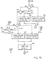
- FIG. 4A and 4B A flow diagram 400 of decompression operations in accordance with the principles of the present invention is shown in Figs. 4A and 4B.
- Figs. 4A and 4B are coupled with coupling symbols A 450, B 451, and C 452. These coupling symbols 450-452 have the same reference numerals in both, Fig. 4A and Fig. 4B.
- the flow diagram is implemented in the decompression processor 158 by accessing icon parameters from the compressed data memory 154 and by storing blocks of pixels related thereto into the image memory 162.
- Each block of pixels is decompressed by accessing an icon and the related attributes from the compressed data memory 154, scanning a block of 100 pixels by 100 pixels into the appropriate block position in the image memory 162 in response to the icon that is related to that block of pixels, and then advancing to the next icon and block of pixels in sequence.
- the scanning of pixels into a block of pixels in the image memory 162 is performed in raster scan form, column by column and row by row for each of ten columns in a row of pixels and for ten rows of pixels.
- the sequencing of blocks of pixels into the image memory 162 is performed in raster scan form, column by column and row by row for each of ten columns in a row of blocks and for ten rows of blocks.
- the accessing of icons and attributes from the compressed data memory 154 is performed in sequence consistent with the block by block operations.
- the program enters the decompression program through the ENTER operation 410 (Fig. 4A).
- the program then proceeds to the BLOCK INITIALIZATION operation 411 to initialize the block related parameters, which includes initializing the row address R B to the zero row in the image memory 162, initializing the column address C B to the zero column in the image memory 162, and initializing the icon address I B to the zero icon address in the compressed data memory 154.
- the zero row address and the zero column address for the block of pixels in the image memory 162 identifies the corner of the image memory 162 at which the block raster scan begins.
- the program then proceeds to the BLOCK LOOP of operations 441 which is executed iteratively, once for each block of pixels within an image.
- the BLOCK LOOP 441 commences with the ACCESS ICON operation 412 where the icon is accessed from the I B address in the compressed data memory 154.
- the program then proceeds to the PIXEL INITIALIZATION operation 413 to initialize the pixel related parameters in the selected block of pixels addressed by the current values of C B and R B , as initialized in the BLOCK INITIALIZATION operation 411 above and as updated in the UPDATE BLOCK COLUMN operation 430 and in the UPDATE BLOCK ROW operation 434 below.
- the row address R P is initialized to the zero row in the selected block and the column address C P is initialized to the zero column in the selected block.
- the zero row address and the zero column address for the pixel in the selected block identifies the corner of the selected block at which the pixel raster scan begins.
- the program then proceeds to the PIXEL LOOP of operations 442 which is executed iteratively, once for each pixel within a block.
- the PIXEL LOOP 442 commences with the ICON TEST operation 415 which tests the icon accessed in the ACCESS ICON operation 412 and calculates a position parameter associated with the current pixel in one of the CALCULATE operations 420, 430, 440, 450, or 450.
- the sign of the position parameter is indicative of whether the pixel is an interior pixel, as indicated by a negative sign, or an exterior pixel, as indicated by a positive sign.
- the F(C P ,R P ) term is the sign and magnitude of the pixel position parameter for the current pixel in the block of pixels
- the g(C P ,R P ) term and the h(C P ,R P ) term are the signs and magnitudes of intermediate position parameters
- the ⁇ term is the angle of the principle axes
- the C P and R P terms are the coordinates of the current pixel in the block
- the ABS[ ] term means the absolute magnitude of the bracketed term
- the Sn[ ] term means the sign of the bracketed term
- the OR term means a logical OR operation.
- the program branches along the FLAT path from the ICON TEST operation 415 to the CALCULATE FLAT INTENSITY operation 420 where the position parameter polarity is set to be positive. This is because all pixel intensities in a flat icon block of pixels have the same intensity, which intensity is stored as an exterior intensity attribute.
- the program branches along the EDGE path from the ICON TEST operation 415 to the CALCULATE EDGE INTENSITY operation 430.
- the program branches along the RIBBON path from the ICON TEST operation 415 to the CALCULATE RIBBON INTENSITY operation 440.
- the X 0 and Y 0 terms are the coordinates of the center position of the corner and the Width term is the width of the corner 356, as shown in Fig. 3D.
- the Sn[F(C P ,R P )] equation means the sign of the F(C P ,R P ) term is positive (implying an exterior intensity) when either the g(C P ,R P ) term or the h(C P ,R P ) term is positive and the sign of the F(C P ,R P ) term is negative (implying an interior intensity) when both the g(C P ,R P ) term and the h(C P ,R P ) term are negative.
- the X 0 and Y 0 terms are the coordinates of the center position of the spot, the Width term is the width 366 of the spot in a first principle axis direction, and the Length term is the length 368 of the spot in a second principle axis direction.
- the Sn[F(C P ,R P )] equation means the sign of the F(C P ,R P ) term is positive (implying an exterior intensity) when either the g(C P ,R P ) term or the h(C P ,R P ) term is positive and the sign of the F(C P ,R P ) term is negative (implying an interior intensity) when both the g(C P ,R P ) term and the h(C P ,R P ) term are negative.
- the program then proceeds from the selected one of the CALCULATE operations 420, 430, 440, 450, 460 to the SIGN TEST operation 417 where the sign of the position parameter is tested. If the sign of the position parameter is positive, then the program proceeds along the POSITIVE path to the STORE EXTERIOR INTENSITY operation 416, where the exterior intensity attribute for the current icon is stored in a pixel location in the image memory 162 addressed by the concatenated total column address CT and total row address RT in memory map form.
- the program proceeds along the NEGATIVE path to the STORE INTERIOR INTENSITY operation 419, where the interior intensity attribute for the current icon is stored in a pixel location in the image memory 162 addressed by the concatenated total column address CT and total row address RT in memory map form.
- This arrangement of keeping the pixel addresses and the block addresses separate and then combining them in the STORE EXTERIOR INTENSITY operation 416 and in the STORE INTERIOR INTENSITY operation 419 facilitates the selection of the blocks of pixels in raster scan form and the scanning of pixel intensities into each block of pixels in raster scan form.
- the program is coupled from Fig. 4A to Fig. 4B through coupling symbol A 450 (Fig.4A and Fig. 4B).
- the program completes the current iteration through the PIXEL LOOP 442.
- the C P address is incremented to the next pixel in the row of pixels and the R P address is preserved.
- the program then loops back in the PIXEL LOOP 442 from coupling symbol C 452 (Fig. 4B) to coupling symbol C 452 (Fig. 4A) and then to the ICON TEST operation 415 to process the next pixel in the current block of pixels.
- C P C PMAX TEST operation 418
- the program then completes the current iteration through the BLOCK LOOP 441.
- the image memory 162 and the compressed data memory 154 may be implemented as different memories and the decompression processor 158 may be partitioned to be in separate processors or in different portions of the same processor.
- the decompression processor 158 may be implemented in parallel processing form, in pipeline processing form, in parallel pipeline processing form, or in other processing forms.
- the decompression processor 158 may be implemented for example by a stored program processor or by a special purpose hardwired processor. Stored program processors may be implemented for example by microprocessors, by array processors, or by RISC processors.
Landscapes
- Engineering & Computer Science (AREA)
- Multimedia (AREA)
- Signal Processing (AREA)
- Compression Of Band Width Or Redundancy In Fax (AREA)
- Digital Computer Display Output (AREA)
- Compression Or Coding Systems Of Tv Signals (AREA)
- Image Processing (AREA)
- Reduction Or Emphasis Of Bandwidth Of Signals (AREA)
Claims (22)
- Daten-Dekompressionssystem zum Erzeugen und Anzeigen eines dekomprimierten Bildes, umfassend:einen Eingangsspeicher (154), der eingerichtet ist, ein datenkomprimiertes Bild zu speichern, das eine Mehrzahl von Sinnbildern (128) umfaßt, wobei jedes Sinnbild vorbestimmte Attribute besitzt, die mit ihm verbunden sind und den Bildinhalt eines Pixelblocks darstellen und ein Attribut einschließen, das einen Hauptachsenwinkel (φ) eines Merkmals in dem Pixelblock darstellt;einen mit dem Eingangsspeicher verbundenen Dekompressions-Prozessor (158), der eingerichtet ist, ein datendekomprimiertes Bild zu erzeugen, das eine Kombination des durch die Mehrzahl von Sinnbildern des datenkomprimierten Bildes dargestellten Bildinhalts ist,wobei der Dekompressions-Prozessor (158) einen Hauptachsen-Prozessor umfaßt, um das datendekomprimierte Bild als eine Mehrzahl von dekomprimierten Pixelblöcken zu erzeugen, wobei jeder dekomprimierte Pixelblock durch den Hauptachsen-Prozessor unter Verwendung des Hauptachsenwinkels erzeugt wird, undeine Bildanzeigeeinrichtung (162, 124), die mit dem Dekompressions-Prozessor verbunden ist und das datendekomprimierte Bild anzeigt.
- Daten-Dekompressionssystem nach Anspruch 1, bei dem der Dekompressions-Prozessor eingerichtet ist, jedes der Mehrzahl von Sinnbildern (128) unabhängig zu verarbeiten, um das datendekomprimierte Bild zu erzeugen.
- Daten-Dekompressionssystem nach Anspruch 1, bei dem der Dekompressions-Prozessor (158) einen Pixelblock-Prozessor umfaßt, der eingerichtet ist, das datendekomprimierte Bild als eine Mehrzahl von dekomprimierten Pixelblöcken zu erzeugen, wobei jeder dekomprimierte Pixelblock als Reaktion auf die Dekompressionsverarbeitung eines der Sinnbilder (128) des datenkomprimierten Bildes erzeugt wird.
- Daten-Dekompressionssystem nach Anspruch 1, bei dem der Dekompressions-Prozessor (158) einen Pixelblock-Prozessor umfaßt, der eingerichtet ist, das datendekomprimierte Bild als eine Mehrzahl von dekomprimierten Pixelmerkmalblöcken zu erzeugen, wobei jeder dekomprimierte Pixelblock als Reaktion auf die Dekompressionsverarbeitung eines der Sinnbilder (128) des datenkomprimierten Bildes erzeugt wird, bei dem die Mehrzahl von Sinnbildern ein Flächensinnbild umfaßt und bei dem der Pixelblock-Prozessor einen Flächensinnbild-Prozessor umfaßt, der eingerichtet ist, dekomprimierte Pixelblöcke als Flächenbild-Pixelblöcke mit einer gleichförmigen Intensität als Reaktion auf Flächensinnbilder zu erzeugen.
- Daten-Dekompressionssystem nach Anspruch 1, bei dem der Dekompressions-Prozessor (158) einen Pixelblock-Prozessor umfaßt, der eingerichtet ist, das datendekomprimierte Bild als eine Mehrzahl von dekomprimierten Pixelmerkmalblöcken zu erzeugen, wobei jeder dekomprimierte Pixelblock als Reaktion auf die Dekompressionsverarbeitung eines der Sinnbilder des datenkomprimierten Bildes erzeugt wird, bei dem die Mehrzahl von Sinnbildern (128) ein Kantensinnbild (128b) umfaßt und bei dem der Pixelblock-Prozessor einen Kantensinnbild-Prozessor umfaßt, der eingerichtet ist, dekomprimierte Pixel blöcke als Kantenbildmerkmal-Pixelblöcke mit einer einzigen Kante, die zwei Intensitätsbereiche trennt, zu erzeugen, wobei jeder Intensitätsbereich eine Intensität aufweist, die sich von der Intensität des anderen Intensitätsbereiches unterscheidet.
- Daten-Dekompressionssystem nach Anspruch 1, bei dem der Dekompressions-Prozessor (158) einen Pixelblock-Prozessor umfaßt, der eingerichtet ist, das datendekomprimierte Bild als eine Mehrzahl von dekomprimierten Pixelmerkmalblöcken zu erzeugen, wobei jeder dekomprimierte Pixelblock als Reaktion auf die Dekompressionsverarbeitung eines der Sinnbilder (128) des datenkomprimierten Bildes erzeugt wird, bei dem die Mehrzahl von Sinnbildern ein Bandsinnbild (128c) umfaßt und bei dem der Pixelblock-Prozessor einen Bandsinnbild-Prozessor umfaßt, der eingerichtet ist, dekomprimierte Pixelblöcke als Bandbildmerkmal-Pixelblöcke mit einer äußeren Intensität und mit einem Band einer inneren Intensität zu erzeugen, das durch zwei Kanten gebildet wird und einen Pixelblock durchquert.
- Daten-Dekompressionssystem nach Anspruch 1, bei dem der Dekompressions-Prozessor (158) einen Pixelblock-Prozessor umfaßt, der eingerichtet ist, das datendekomprimierte Bild als eine Mehrzahl von dekomprimierten Pixelmerkmalblöcken zu erzeugen, wobei jeder dekomprimierte Pixelblock als Reaktion auf die Dekompressionsverarbeitung eines der Sinnbilder des datenkomprimierten Bildes erzeugt wird, bei dem die Mehrzahl von Sinnbildern (128) ein Eckensinnbild (128d) umfaßt und bei dem der Pixelblock-Prozessor einen Eckensinnbild-Prozessor umfaßt, der eingerichtet ist, dekomprimierte Pixelblöcke als Eckenbildmerkmal-Pixelblöcke mit einer äußeren Intensität und mit einer Ecke mit einer inneren Intensität zu erzeugen, die durch drei Kanten innerhalb eines Pixelblocks gebildet wird.
- Daten-Dekompressionssystem nach Anspruch 1, bei dem der Dekompressions-Prozessor einen Pixelblock-Prozessor umfaßt, der eingerichtet ist, das datendekomprimierte Bild als eine Mehrzahl von dekomprimierten Pixelmerkmalblöcken zu erzeugen, wobei jeder dekomprimierte Pixelblock als Reaktion auf die Dekompressionsverarbeitung eines der Sinnbilder des datenkomprimierten Bildes erzeugt wird, bei dem die Mehrzahl von Sinnbildern (128) ein Fleckensinnbild (128e) umfaßt und bei dem der Pixelblock-Prozessor einen Fleckensinnbild-Prozessor umfaßt, der eingerichtet ist, dekomprimierte Pixelblöcke als Fleckenbildmerkmal-Pixelblöcke mit einer äußeren Intensität und mit einem Flecken mit einer inneren Intensität zu erzeugen, der durch vier Kanten innerhalb eines Pixelblocks gebildet wird.
- Bilddatenbank-Speichersystem, umfassend:eine Bildeingangsschaltung, die eingerichtet ist, ein Eingangsbild mit einer Vielzahl von Pixels zu erzeugen;einen mit der Bildeingangsschaltung verbundenen Datenkompressions-Prozessor (112), der eingerichtet ist, ein datenkomprimiertes Bild, das eine Mehrzahl von Sinnbildern umfaßt, als Reaktion auf das Eingangsbild zu erzeugen, wobei jedes Sinnbild vorbestimmte Attribute besitzt, die mit ihm verbunden sind und den Bildinhalt eines Pixelblocks darstellen und ein Attribut einschließen, das einen Hauptachsenwinkel eines Merkmals in dem Pixelblock darstellt;einen Datenbankspeicher (136), der mit dem Datenkompressions-Prozessor verbunden und eingerichtet ist, das die Mehrzahl von Sinnbildern umfassende datenkomprimierte Bild zu speichern;einen Dekompressions-Prozessor (120), der mit dem Datenbankspeicher verbunden und eingerichtet ist, ein datendekomprimiertes Bild mit einer Vielzahl von Pixels als Reaktion auf das die Mehrzahl von Sinnbildern umfassende datenkomprimierte Bild zu erzeugen;wobei der Dekompressions-Prozessor einen Hauptachsen-Prozessor umfaßt, der eingerichtet ist, das datendekomprimierte Bild als eine Mehrzahl von dekomprimierten Pixelblöcken zu erzeugen, wobei jeder dekomprimierte Pixelblock durch Dekompressionsverarbeitung eines Sinnbildes um die Hauptachse unter Verwendung des Hauptachsenwinkels erzeugt wird, undeine Bildanzeigeeinrichtung (124), die mit dem Dekompressions-Prozessor verbunden ist und das datendekomprimierte Bild anzeigt.
- Datenbank-Speichersystem nach Anspruch 9, bei dem der Dekompressions-Prozessor eingerichtet ist, jedes der Mehrzahl von Sinnbildern unabhängig zu verarbeiten, um das datendekomprimierte Bild zu erzeugen.
- Datenbanksystem nach Anspruch 9, bei dem der Dekompressions-Prozessor (158) einen Pixelblock-Prozessor umfaßt, der eingerichtet ist, das datendekomprimierte Bild als eine Mehrzahl von dekomprimierten Pixelblöcken zu erzeugen, wobei jeder deKomprimierte Pixelblock als Reaktion auf die Dekompressionsverarbeitung eines Sinnbildes erzeugt wird.
- Bildübertragungssysten, umfassend:eine Bildeingangsschaltung, die eingerichtet ist, ein Eingangsbild mit einer Vielzahl von Pixels zu erzeugen;einen mit der Bildeingangsschaltung verbundenen Datenkompressions-Prozessor (112), der eingerichtet ist, ein datenkomprimiertes Bild, das eine Mehrzahl von Sinnbildern umfaßt, als Reaktion auf das Eingangsbild zu erzeugen, wobei jedes Sinnbild vorbestimmte Attribute besitzt, die mit ihm verbunden sind und den Bildinhalt eines Pixelblocks darstellen und ein Attribut einschließen, das einen Hauptachsenwinkel eines Merkmals in dem Pixelblock darstellt;ein Kommunikations-Untersystem (116), das mit dem Datenkompressions-Prozessor verbunden und eingerichtet ist, das datenkomprimierte Bild mit der Mehrzahl von Sinnbildern zu einem entfernten Ort zu übertragen;einen an dem entfernten Ort gelegenen und mit dem übertragungssystem verbundenen Dekompressions-Prozessor (120), der eingerichtet ist, ein datendekomprimiertes Bild mit einer Vielzahl von Pixels als Reaktion auf das datenkomprimierte Bild mit der Mehrzahl von Sinnbildern zu erzeugen,wobei der Dekompressions-Prozessor einen Hauptachsen-Prozessor umfaßt, der eingerichtet ist, das datendekomprimierte Bild als eine Mehrzahl von dekomprimierten Pixelblöcken zu erzeugen, wobei jeder dekomprimierte Pixelblock durch Dekompressionsverarbeitung eines Sinnbildes um die Hauptachse unter Verwendung des Hauptachsenwinkels erzeugt wird, undeine an der entfernten Stelle gelegene und mit dem Dekompressions-Prozessor verbundene Bildanzeigeeinrichtung (124), die das datendekomprimierte Bild anzeigt.
- Übertragungssystem nach Anspruch 12, bei dem der Dekompressions-Prozessor (120) eingerichtet ist, jedes der Mehrzahl von Sinnbildern unabhängig von der Verarbeitung jedes der anderen der Sinnbilder zu verarbeiten, um das datendekomprimierte Bild zu erzeugen.
- Übertragungssystem nach Anspruch 12, bei dem der Dekompressions-Prozessor (120) einen Pixelblock-Prozessor umfaßt, der eingerichtet ist, das datendekomprimierte Bild als eine Mehrzahl von dekomprimierten Pixelblöcken zu erzeugen, wobei jeder dekomprimierte Pixelblock als Reaktion auf die Dekompressionsverarbeitung eines Sinnbildes erzeugt wird.
- Verfahren zur Daten-Dekompression eines Bildes, das die folgenden Schritte umfaßt:Speichern einer Mehrzahl von Sinnbildern (128), die mit einem datenkomprimierten Bild in Beziehung stehen, in einem Speicher, wobei jedes Sinnbild vorbestimmte Attribute besitzt, die mit ihm verbunden sind und den Bildinhalt eines Pixelblocks darstellen und ein Attribut einschließen, das einen Hauptachsenwinkel eines Merkmals in dem Pixelblock darstellt;Zugreifen (412) auf jedes Sinnbild der in dem Speicher gespeicherten Mehrzahl von Sinnbildern;Erzeugen eines datendekomprimierten Bildes als eine Mehrzahl von dekomprimierten Pixelblöcken durch Dekompressionsverarbeitung eines Sinnbildes um eine Hauptachse unter Verwendung des Hauptachsenwinkels undKombinieren der dekomprimierten Pixelblöcke, um ein dekomprimiertes Bild zu erzeugen.
- Verfahren nach Anspruch 15, bei dem jedes der Mehrzahl von Sinnbildern unabhängig verarbeitet wird, um das datendekomprimierte Bild zu erzeugen.
- Verfahren nach Anspruch 15, bei dem das datendekomprimierte Bild als eine Mehrzahl von dekomprimierten Pixelblöcken erzeugt wird, wobei jeder dekomprimierte Pixelblock als Reaktion auf die Dekompressionsverarbeitung eines der Sinnbilder des datenkomprimierten Bildes erzeugt wird.
- Verfahren nach Anspruch 15, bei dem die Mehrzahl von Sinnbildern ein Flächensinnbild umfaßt, und
der Erzeugungsschritt das Erzeugen von dekomprimierten Pixelblöcken als Flächenbildmerkmal-Pixelblöcke mit gleichförmiger Intensität als Reaktion auf Flächensinnbilder umfaßt. - Verfahren nach Anspruch 15, bei dem die Mehrzahl von Sinnbildern ein Kantensinnbild umfaßt, und
der Erzeugungsschritt das Erzeugen von dekomprimierten Pixelblöcken als Kantenbildmerkmal-Pixelblöcke mit einer einzigen Kante, die zwei Intensitätsbereiche trennt, umfaßt, wobei jeder Intensitätsbereich eine Intensität aufweist, die sich von der Intensität des anderen Intensitätsbereiches unterscheidet. - Verfahren nach Anspruch 15, bei dem die Mehrzahl von Sinnbildern ein Bandsinnbild umfaßt, und
der Erzeugungsschritt das Erzeugen von dekomprimierten Pixelblöcken als Bandbildmerkmal-Pixelblöcke mit einer äußeren Intensität und mit einem Band einer inneren Intensität umfaßt, das durch zwei Kanten gebildet wird und einen Block von dekomprimierten Pixels durchquert. - Verfahren nach Anspruch 15, bei dem die Mehrzahl von Sinnbildern ein Eckensinnbild umfaßt, und
der Erzeugungsschritt das Erzeugen von dekomprimierten Pixelblöcken als Eckenbildmerkmal-Pixelblöcke mit einer äußeren Intensität und mit einer Ecke mit einer inneren Intensität umfaßt, die durch drei Kanten innerhalb eines Pixelblocks gebildet wird. - Verfahren nach Anspruch 15, bei dem die Mehrzahl von Sinnbildern ein Fleckensinnbild umfaßt, und
der Erzeugungsschritt das Erzeugen von dekomprimierten Pixelblöcken als Fleckenbildmerkmal-Pixelblöcke mit einer äußeren Intensität und mit einem Flecken mit einer inneren Intensität umfaßt, der durch vier Kanten innerhalb eines dekomprimierten Pixelblocks gebildet wird.
Applications Claiming Priority (2)
| Application Number | Priority Date | Filing Date | Title |
|---|---|---|---|
| US07/514,779 US5048112A (en) | 1990-04-25 | 1990-04-25 | Data decompression system and method |
| US514779 | 1990-04-25 |
Publications (3)
| Publication Number | Publication Date |
|---|---|
| EP0453827A2 EP0453827A2 (de) | 1991-10-30 |
| EP0453827A3 EP0453827A3 (en) | 1992-08-05 |
| EP0453827B1 true EP0453827B1 (de) | 1996-09-04 |
Family
ID=24048660
Family Applications (1)
| Application Number | Title | Priority Date | Filing Date |
|---|---|---|---|
| EP91105250A Expired - Lifetime EP0453827B1 (de) | 1990-04-25 | 1991-04-03 | Verbessertes Datenkomprimierungssystem und -verfahren |
Country Status (12)
| Country | Link |
|---|---|
| US (1) | US5048112A (de) |
| EP (1) | EP0453827B1 (de) |
| JP (1) | JP3115632B2 (de) |
| KR (1) | KR950010739B1 (de) |
| AU (1) | AU634372B2 (de) |
| CA (1) | CA2039080C (de) |
| DE (1) | DE69121758T2 (de) |
| ES (1) | ES2092519T3 (de) |
| GR (1) | GR3021868T3 (de) |
| IL (1) | IL97723A (de) |
| NO (1) | NO303806B1 (de) |
| TR (1) | TR26258A (de) |
Families Citing this family (22)
| Publication number | Priority date | Publication date | Assignee | Title |
|---|---|---|---|---|
| JP3005007B2 (ja) * | 1989-12-21 | 2000-01-31 | キヤノン株式会社 | 画像符号化装置 |
| JP3297445B2 (ja) * | 1991-04-23 | 2002-07-02 | キヤノン株式会社 | 出力方法及び装置 |
| FR2681750A1 (fr) * | 1991-09-20 | 1993-03-26 | Thomson Csf | Procede de compression d'images. |
| US8352400B2 (en) | 1991-12-23 | 2013-01-08 | Hoffberg Steven M | Adaptive pattern recognition based controller apparatus and method and human-factored interface therefore |
| US10361802B1 (en) | 1999-02-01 | 2019-07-23 | Blanding Hovenweep, Llc | Adaptive pattern recognition based control system and method |
| US5583953A (en) * | 1993-06-30 | 1996-12-10 | Xerox Corporation | Intelligent doubling for low-cost image buffers |
| CZ286929B6 (en) * | 1993-08-05 | 2000-08-16 | Motorola Inc | Telefax communication process within a communication system with selective calling and communication system for making the same |
| US5521991A (en) * | 1993-10-29 | 1996-05-28 | International Business Machines Corporation | Method and system for fast forms recognition of document form images |
| AU694531B2 (en) * | 1994-07-01 | 1998-07-23 | Commonwealth Scientific And Industrial Research Organisation | Fractal representation of data |
| AU710946B2 (en) * | 1994-07-01 | 1999-09-30 | Commonwealth Scientific And Industrial Research Organisation | Fractal representation of data |
| AUPM661494A0 (en) * | 1994-07-01 | 1994-07-28 | Commonwealth Scientific And Industrial Research Organisation | Fractal representation of data |
| AUPM661594A0 (en) * | 1994-07-01 | 1994-07-28 | Commonwealth Scientific And Industrial Research Organisation | Fractal representation of data |
| KR0171146B1 (ko) * | 1995-03-18 | 1999-03-20 | 배순훈 | 특징점을 이용한 움직임 벡터 검출 장치 |
| KR0171120B1 (ko) * | 1995-04-29 | 1999-03-20 | 배순훈 | 특징점 기반 움직임 보상을 이용한 비디오 신호 부호화에서의 움직임 영역 설정방법 및 장치 |
| IL114475A0 (en) * | 1995-07-06 | 1995-11-27 | Grid Point Ltd | Method for 2D and 3D image capturing representation processing and compression |
| US6082054A (en) | 1998-08-27 | 2000-07-04 | Silberman; Cyril J. | Retractable stadium roofs and transport mechanism therefor |
| US7966078B2 (en) | 1999-02-01 | 2011-06-21 | Steven Hoffberg | Network media appliance system and method |
| US6415556B1 (en) | 2000-07-03 | 2002-07-09 | Uni-Systems, Inc. | Transport mechanism for large structures such as retractable stadium rooves |
| US20040174361A1 (en) * | 2000-10-13 | 2004-09-09 | Yosef Yomdin | Geometric and brightness modeling of images |
| US6698141B2 (en) | 2001-01-23 | 2004-03-02 | Uni-Systems, Llc | Convertible stadium and method of operating |
| US20050063596A1 (en) * | 2001-11-23 | 2005-03-24 | Yosef Yomdin | Encoding of geometric modeled images |
| WO2010050106A1 (ja) * | 2008-10-27 | 2010-05-06 | パナソニック株式会社 | 画像符号化方法、画像符号化装置および撮像システム |
Family Cites Families (8)
| Publication number | Priority date | Publication date | Assignee | Title |
|---|---|---|---|---|
| US3980809A (en) * | 1973-07-16 | 1976-09-14 | International Business Machines Corporation | Encoding logic for reduced bandwidth pictorial data transmission system |
| DE2423817A1 (de) * | 1973-07-16 | 1975-02-06 | Ibm | Verfahren und schaltungsanordnungen zur codierung zweidimensionaler bildinformationen |
| JPS5929020B2 (ja) * | 1977-06-08 | 1984-07-17 | 松下電器産業株式会社 | 2次元ブロック符号化方法 |
| US4529228A (en) * | 1980-09-02 | 1985-07-16 | Kramer Henry P | Method and apparatus for coding pictorial information for efficient storage, transmission and reproduction |
| JPS61159869A (ja) * | 1985-01-08 | 1986-07-19 | Mitsubishi Electric Corp | ベクトル量子化器 |
| US4758979A (en) * | 1985-06-03 | 1988-07-19 | Chiao Yueh Lin | Method and means for automatically coding and inputting Chinese characters in digital computers |
| JPS6224776A (ja) * | 1985-07-25 | 1987-02-02 | Matsushita Electric Works Ltd | 画像デ−タの圧縮方式 |
| JPS6275782A (ja) * | 1985-09-30 | 1987-04-07 | Canon Inc | 画像符号化装置 |
-
1990
- 1990-04-25 US US07/514,779 patent/US5048112A/en not_active Expired - Lifetime
-
1991
- 1991-03-26 CA CA002039080A patent/CA2039080C/en not_active Expired - Lifetime
- 1991-03-28 IL IL97723A patent/IL97723A/xx not_active IP Right Cessation
- 1991-04-03 EP EP91105250A patent/EP0453827B1/de not_active Expired - Lifetime
- 1991-04-03 DE DE69121758T patent/DE69121758T2/de not_active Expired - Lifetime
- 1991-04-03 ES ES91105250T patent/ES2092519T3/es not_active Expired - Lifetime
- 1991-04-10 AU AU74315/91A patent/AU634372B2/en not_active Expired
- 1991-04-24 JP JP03094263A patent/JP3115632B2/ja not_active Expired - Lifetime
- 1991-04-24 NO NO911628A patent/NO303806B1/no not_active IP Right Cessation
- 1991-04-24 KR KR1019910006608A patent/KR950010739B1/ko not_active Expired - Lifetime
- 1991-04-25 TR TR91/0503A patent/TR26258A/xx unknown
-
1996
- 1996-12-03 GR GR960403279T patent/GR3021868T3/el unknown
Also Published As
| Publication number | Publication date |
|---|---|
| JP3115632B2 (ja) | 2000-12-11 |
| CA2039080C (en) | 1994-10-25 |
| AU7431591A (en) | 1991-11-07 |
| KR950010739B1 (ko) | 1995-09-22 |
| DE69121758D1 (de) | 1996-10-10 |
| IL97723A0 (en) | 1992-06-21 |
| IL97723A (en) | 1997-09-30 |
| NO911628D0 (no) | 1991-04-24 |
| JPH04229321A (ja) | 1992-08-18 |
| CA2039080A1 (en) | 1991-10-26 |
| EP0453827A2 (de) | 1991-10-30 |
| AU634372B2 (en) | 1993-02-18 |
| GR3021868T3 (en) | 1997-03-31 |
| NO911628L (no) | 1991-10-28 |
| ES2092519T3 (es) | 1996-12-01 |
| TR26258A (tr) | 1995-02-15 |
| DE69121758T2 (de) | 1997-01-02 |
| NO303806B1 (no) | 1998-08-31 |
| EP0453827A3 (en) | 1992-08-05 |
| US5048112A (en) | 1991-09-10 |
Similar Documents
| Publication | Publication Date | Title |
|---|---|---|
| EP0453827B1 (de) | Verbessertes Datenkomprimierungssystem und -verfahren | |
| US4751660A (en) | Determining orientation of transformed image | |
| US6614448B1 (en) | Circuit and method for displaying images using multisamples of non-uniform color resolution | |
| US6825847B1 (en) | System and method for real-time compression of pixel colors | |
| DE69130545T2 (de) | System zur Erzeugung einer texturierten Perspektivsicht | |
| US6677957B2 (en) | Hardware-accelerated visualization of surface light fields | |
| US4570233A (en) | Modular digital image generator | |
| US4827413A (en) | Modified back-to-front three dimensional reconstruction algorithm | |
| US6476811B1 (en) | Method and apparatus for compressing parameter values for pixels in a display frame | |
| US4841292A (en) | Third dimension pop up generation from a two-dimensional transformed image display | |
| US7062419B2 (en) | Surface light field decomposition using non-negative factorization | |
| US5613051A (en) | Remote image exploitation display system and method | |
| US4827445A (en) | Image buffer having logic-enhanced pixel memory cells and method for setting values therein | |
| US5109438A (en) | Data compression system and method | |
| WO1998029836A9 (en) | Circuit for determining non-homogenous second order perspective texture mapping coordinates using linear interpolation | |
| US6985638B1 (en) | Efficient perspective transformation of partial images in composing a single image | |
| US5719598A (en) | Graphics processor for parallel processing a plurality of fields of view for multiple video displays | |
| US5295234A (en) | Apparatus for displaying a three dimensional object which appears substantially the same in different display directions by modifying stored image data by a scale factor | |
| EP1456817B1 (de) | Vorrichtung und verfahren zur bildverzerrung | |
| US7053894B2 (en) | Compression of surface light fields | |
| US6870542B2 (en) | System and method for filtering graphics data on scanout to a monitor | |
| US7064752B1 (en) | Multi-function unit of a graphics system for updating a hierarchical Z buffer | |
| JP2891862B2 (ja) | 画像圧縮装置および画像圧縮方法 | |
| EP1351189A1 (de) | Bildbearbeitung | |
| Salomon | First Principles |
Legal Events
| Date | Code | Title | Description |
|---|---|---|---|
| PUAI | Public reference made under article 153(3) epc to a published international application that has entered the european phase |
Free format text: ORIGINAL CODE: 0009012 |
|
| AK | Designated contracting states |
Kind code of ref document: A2 Designated state(s): CH DE ES FR GB GR IT LI NL SE |
|
| PUAL | Search report despatched |
Free format text: ORIGINAL CODE: 0009013 |
|
| AK | Designated contracting states |
Kind code of ref document: A3 Designated state(s): CH DE ES FR GB GR IT LI NL SE |
|
| 17P | Request for examination filed |
Effective date: 19930129 |
|
| 17Q | First examination report despatched |
Effective date: 19941222 |
|
| GRAH | Despatch of communication of intention to grant a patent |
Free format text: ORIGINAL CODE: EPIDOS IGRA |
|
| GRAH | Despatch of communication of intention to grant a patent |
Free format text: ORIGINAL CODE: EPIDOS IGRA |
|
| GRAA | (expected) grant |
Free format text: ORIGINAL CODE: 0009210 |
|
| AK | Designated contracting states |
Kind code of ref document: B1 Designated state(s): CH DE ES FR GB GR IT LI NL SE |
|
| REG | Reference to a national code |
Ref country code: CH Ref legal event code: NV Representative=s name: ISLER & PEDRAZZINI AG |
|
| REF | Corresponds to: |
Ref document number: 69121758 Country of ref document: DE Date of ref document: 19961010 |
|
| ET | Fr: translation filed | ||
| ET | Fr: translation filed | ||
| ITF | It: translation for a ep patent filed | ||
| REG | Reference to a national code |
Ref country code: ES Ref legal event code: FG2A Ref document number: 2092519 Country of ref document: ES Kind code of ref document: T3 |
|
| REG | Reference to a national code |
Ref country code: GR Ref legal event code: FG4A Free format text: 3021868 |
|
| PGFP | Annual fee paid to national office [announced via postgrant information from national office to epo] |
Ref country code: FR Payment date: 19970307 Year of fee payment: 7 |
|
| PGFP | Annual fee paid to national office [announced via postgrant information from national office to epo] |
Ref country code: SE Payment date: 19970314 Year of fee payment: 7 |
|
| PGFP | Annual fee paid to national office [announced via postgrant information from national office to epo] |
Ref country code: GB Payment date: 19970319 Year of fee payment: 7 |
|
| PGFP | Annual fee paid to national office [announced via postgrant information from national office to epo] |
Ref country code: CH Payment date: 19970324 Year of fee payment: 7 |
|
| PGFP | Annual fee paid to national office [announced via postgrant information from national office to epo] |
Ref country code: GR Payment date: 19970328 Year of fee payment: 7 |
|
| PGFP | Annual fee paid to national office [announced via postgrant information from national office to epo] |
Ref country code: ES Payment date: 19970417 Year of fee payment: 7 |
|
| PLBE | No opposition filed within time limit |
Free format text: ORIGINAL CODE: 0009261 |
|
| STAA | Information on the status of an ep patent application or granted ep patent |
Free format text: STATUS: NO OPPOSITION FILED WITHIN TIME LIMIT |
|
| 26N | No opposition filed | ||
| PG25 | Lapsed in a contracting state [announced via postgrant information from national office to epo] |
Ref country code: GB Free format text: LAPSE BECAUSE OF NON-PAYMENT OF DUE FEES Effective date: 19980403 |
|
| PG25 | Lapsed in a contracting state [announced via postgrant information from national office to epo] |
Ref country code: SE Free format text: LAPSE BECAUSE OF NON-PAYMENT OF DUE FEES Effective date: 19980404 Ref country code: ES Free format text: LAPSE BECAUSE OF EXPIRATION OF PROTECTION Effective date: 19980404 |
|
| PG25 | Lapsed in a contracting state [announced via postgrant information from national office to epo] |
Ref country code: FR Free format text: THE PATENT HAS BEEN ANNULLED BY A DECISION OF A NATIONAL AUTHORITY Effective date: 19980430 Ref country code: CH Free format text: LAPSE BECAUSE OF NON-PAYMENT OF DUE FEES Effective date: 19980430 Ref country code: GR Free format text: LAPSE BECAUSE OF NON-PAYMENT OF DUE FEES Effective date: 19980430 Ref country code: LI Free format text: LAPSE BECAUSE OF NON-PAYMENT OF DUE FEES Effective date: 19980430 |
|
| GBPC | Gb: european patent ceased through non-payment of renewal fee |
Effective date: 19980403 |
|
| REG | Reference to a national code |
Ref country code: CH Ref legal event code: PL |
|
| EUG | Se: european patent has lapsed |
Ref document number: 91105250.4 |
|
| REG | Reference to a national code |
Ref country code: FR Ref legal event code: ST |
|
| NLS | Nl: assignments of ep-patents |
Owner name: RAYTHEON COMPANY;HE HOLDINGS, INC. |
|
| REG | Reference to a national code |
Ref country code: ES Ref legal event code: FD2A Effective date: 20000301 |
|
| PG25 | Lapsed in a contracting state [announced via postgrant information from national office to epo] |
Ref country code: IT Free format text: LAPSE BECAUSE OF NON-PAYMENT OF DUE FEES;WARNING: LAPSES OF ITALIAN PATENTS WITH EFFECTIVE DATE BEFORE 2007 MAY HAVE OCCURRED AT ANY TIME BEFORE 2007. THE CORRECT EFFECTIVE DATE MAY BE DIFFERENT FROM THE ONE RECORDED. Effective date: 20050403 |
|
| PGFP | Annual fee paid to national office [announced via postgrant information from national office to epo] |
Ref country code: NL Payment date: 20100402 Year of fee payment: 20 Ref country code: DE Payment date: 20100430 Year of fee payment: 20 |
|
| REG | Reference to a national code |
Ref country code: DE Ref legal event code: R071 Ref document number: 69121758 Country of ref document: DE |
|
| REG | Reference to a national code |
Ref country code: NL Ref legal event code: V4 Effective date: 20110403 |
|
| PG25 | Lapsed in a contracting state [announced via postgrant information from national office to epo] |
Ref country code: NL Free format text: LAPSE BECAUSE OF EXPIRATION OF PROTECTION Effective date: 20110403 |
|
| PG25 | Lapsed in a contracting state [announced via postgrant information from national office to epo] |
Ref country code: DE Free format text: LAPSE BECAUSE OF EXPIRATION OF PROTECTION Effective date: 20110403 |