EP0453865A2 - Angular gas cap for thermal spray gun - Google Patents
Angular gas cap for thermal spray gun Download PDFInfo
- Publication number
- EP0453865A2 EP0453865A2 EP91105589A EP91105589A EP0453865A2 EP 0453865 A2 EP0453865 A2 EP 0453865A2 EP 91105589 A EP91105589 A EP 91105589A EP 91105589 A EP91105589 A EP 91105589A EP 0453865 A2 EP0453865 A2 EP 0453865A2
- Authority
- EP
- European Patent Office
- Prior art keywords
- entrance
- axis
- exit
- channel
- radius
- Prior art date
- Legal status (The legal status is an assumption and is not a legal conclusion. Google has not performed a legal analysis and makes no representation as to the accuracy of the status listed.)
- Granted
Links
- 239000007921 spray Substances 0.000 title claims abstract description 53
- 239000007789 gas Substances 0.000 claims description 72
- 239000000843 powder Substances 0.000 claims description 22
- 238000002485 combustion reaction Methods 0.000 claims description 11
- 239000000203 mixture Substances 0.000 claims description 9
- 239000000463 material Substances 0.000 claims description 7
- QVGXLLKOCUKJST-UHFFFAOYSA-N atomic oxygen Chemical compound [O] QVGXLLKOCUKJST-UHFFFAOYSA-N 0.000 claims description 5
- 239000012159 carrier gas Substances 0.000 claims description 5
- 239000001301 oxygen Substances 0.000 claims description 5
- 229910052760 oxygen Inorganic materials 0.000 claims description 5
- 239000000567 combustion gas Substances 0.000 claims 1
- 238000000576 coating method Methods 0.000 description 4
- 238000005507 spraying Methods 0.000 description 4
- 239000011248 coating agent Substances 0.000 description 3
- 239000002245 particle Substances 0.000 description 3
- 230000003628 erosive effect Effects 0.000 description 2
- 239000000446 fuel Substances 0.000 description 2
- 238000002347 injection Methods 0.000 description 2
- 239000007924 injection Substances 0.000 description 2
- 230000013011 mating Effects 0.000 description 2
- 238000002844 melting Methods 0.000 description 2
- 230000008018 melting Effects 0.000 description 2
- 229910000906 Bronze Inorganic materials 0.000 description 1
- 229910000760 Hardened steel Inorganic materials 0.000 description 1
- 229910000831 Steel Inorganic materials 0.000 description 1
- 230000006978 adaptation Effects 0.000 description 1
- 239000003570 air Substances 0.000 description 1
- 238000013459 approach Methods 0.000 description 1
- 238000005422 blasting Methods 0.000 description 1
- 239000010974 bronze Substances 0.000 description 1
- 239000000919 ceramic Substances 0.000 description 1
- 230000005465 channeling Effects 0.000 description 1
- KUNSUQLRTQLHQQ-UHFFFAOYSA-N copper tin Chemical compound [Cu].[Sn] KUNSUQLRTQLHQQ-UHFFFAOYSA-N 0.000 description 1
- 239000010432 diamond Substances 0.000 description 1
- 230000000694 effects Effects 0.000 description 1
- 238000010285 flame spraying Methods 0.000 description 1
- 239000002737 fuel gas Substances 0.000 description 1
- 238000010438 heat treatment Methods 0.000 description 1
- 230000006698 induction Effects 0.000 description 1
- 238000004519 manufacturing process Methods 0.000 description 1
- 239000002184 metal Substances 0.000 description 1
- 238000012986 modification Methods 0.000 description 1
- 230000004048 modification Effects 0.000 description 1
- 229940098458 powder spray Drugs 0.000 description 1
- 230000035939 shock Effects 0.000 description 1
- 229910001220 stainless steel Inorganic materials 0.000 description 1
- 239000010935 stainless steel Substances 0.000 description 1
- 239000010959 steel Substances 0.000 description 1
- 239000000758 substrate Substances 0.000 description 1
- 238000007751 thermal spraying Methods 0.000 description 1
Images

Classifications
-
- B—PERFORMING OPERATIONS; TRANSPORTING
- B05—SPRAYING OR ATOMISING IN GENERAL; APPLYING FLUENT MATERIALS TO SURFACES, IN GENERAL
- B05B—SPRAYING APPARATUS; ATOMISING APPARATUS; NOZZLES
- B05B7/00—Spraying apparatus for discharge of liquids or other fluent materials from two or more sources, e.g. of liquid and air, of powder and gas
- B05B7/16—Spraying apparatus for discharge of liquids or other fluent materials from two or more sources, e.g. of liquid and air, of powder and gas incorporating means for heating or cooling the material to be sprayed
- B05B7/20—Spraying apparatus for discharge of liquids or other fluent materials from two or more sources, e.g. of liquid and air, of powder and gas incorporating means for heating or cooling the material to be sprayed by flame or combustion
- B05B7/201—Spraying apparatus for discharge of liquids or other fluent materials from two or more sources, e.g. of liquid and air, of powder and gas incorporating means for heating or cooling the material to be sprayed by flame or combustion downstream of the nozzle
- B05B7/205—Spraying apparatus for discharge of liquids or other fluent materials from two or more sources, e.g. of liquid and air, of powder and gas incorporating means for heating or cooling the material to be sprayed by flame or combustion downstream of the nozzle the material to be sprayed being originally a particulate material
Definitions
- This invention relates to thermal spray guns and particularly to a gas cap for such a gun to deflect the spray stream at an angle.
- Thermal spraying also known as flame spraying, involves the heat softening of a heat fusible material such as metal or ceramic, and propelling the softened material in particulate form against a surface which is to be coated. The heated particles strike the surface where they are quenched and bonded thereto.
- the heat fusible material is supplied to the gun in powder form in a carrier gas.
- Such powders are typically comprised of small particles, e.g., between 100 mesh U. S. Standard screen size (149 microns) and about 2 microns.
- wire is used as the feed material.
- a thermal spray gun normally utilizes a combustion or plasma flame to produce the heat for melting of the powder particles.
- Other heating means may be used as well, such as electric arcs, resistance heaters or induction heaters, and these may be used alone or in combination with other forms of heaters.
- a particular challenge is spraying on the inside surfaces of confined areas such as in holes, pipes and the like.
- the guns normally spray forwardly with a spray distance of at least several centimeters, and an ordinary spray gun is at least 15 cm long, restricting the ability to spray sideways in a small hole.
- various adaptations have been made for coating inside surfaces.
- the nozzle is turned sideways on the end of an extension, as disclosed for a powder flame spray gun in U.S. Patent No. 3,171,599 (Rotolico).
- This is not possible for a wire spray gun since the extension must accommodate the relatively stiff wire. Therefore other deflectors were devised, including blasting the melting wire tip with air from sideways (U.S. Patent No.
- an object of the invention is to provide a novel gas cap for a thermal spray gun, particularly a very high velocity type of gun, for spraying at an angle into confined areas. Another object is to provide an improved thermal spray gun for spraying into confined areas.
- an angular gas cap for a thermal spray gun comprising a gas cap member having a passage extending therethrough with an inlet end and an outlet end, the passage being receptive of a spray stream of a thermal spray burner head from the inlet end.
- the passage includes an entrance channel extending from the inlet end, an exit channel extending to the outlet end, and an intermediate channel connecting between the entrance and exit channels.
- the entrance channel is symmetrical on an entrance axis and the exit channel is symmetrical on an exit axis oriented at a selected angle to the entrance axis greater than zero and preferably between about 30 o and 60 o , with the entrance axis and the exit axis defining a plane.
- the intermediate channel is symmetrical to the plane and has a near portion and a far portion.
- the near portion is generally semicylindrical about the entrance axis.
- the far portion is generally semicylindrical about a far axis segment lying in the plane.
- the far axis segment is offset from the entrance axis in a direction away from the outlet end and oriented at an intermediate angle to the entrance axis between zero and the selected angle, preferably with the three axes intersecting at a common point.
- the far portion has a wall segment distal from the near axis and substantially connecting with adjacent wall segments of the entrance and exit channels.
- the entrance channel is generally cylindrical with an entrance radius
- the exit channel is convergingly conical toward the outlet end which has an exit radius with a value less than the entrance radius.
- the near portion of the intermediate channel has a near radius with a value between the entrance radius and the exit radius, and the far portion has a far radius with a value between the near radius and the exit radius.
- the intermediate channel further has a conically convergent portion symmetrical on the entrance axis connecting from the entrance channel to the near and far portions exclusive of the distal wall segment.
- thermal spray gun incorporating the above-described gas cap.
- the thermal spray gun is a very high velocity type of gun.
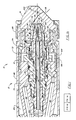
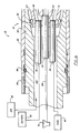
- FIG. 1 is a longitudinal section of a thermal spray gun incorporating the invention.
- FIG. 2 is a longitudinal section of an assembly including a gas cap according to the invention.
- FIG. 3 is an exploded longitudinal section of the gas cap of FIG. 2.
- FIG. 4 is an end view of one member of the gas cap of FIG. 3.
- a thermal spray apparatus is illustrated in FIG. 1.
- a thermal spray gun 10 basically comprises a rear gun body and an extension 12 with a burner head 14 .
- the rear body (not shown) includes valving and passages for supplying gases.
- the burner head is advantageously of the type utilized for very high velocity spray, as disclosed in the aforementioned U.S. Patent No. 4,865,252.
- a gas cap 16 is mounted on the burner head. Fuel, oxygen and air are supplied from respective sources 40 , 42 , 44 to the burner head in the conventional manner as taught in aforementioned U.S. Patent No. 3,122,321.
- the passages for the fuel and oxygen connect to respective rigid pipes 18 , 20 extending from the rear gun body.
- a third pipe 22 for a carrier gas containing powder from a feeder 46 extends similarly, so that the three pipes are held in parallel adjacently to each other.
- Powder feeder 46 is of the conventional or desired type but must be capable of delivering the carrier gas at high enough pressure to carry the powder through back pressures in the nozzle and gas cap.
- the powder/carrier pipe 22 may instead be a wire guide for wire to be thermal sprayed in place of powder.
- These pipes also function to rigidly support the burner head 14 spaced from the rear body by a distance representing a chosen length for the gun extension, ranging from 15 cm to one meter or more.
- a cylindrical siphon plug 24 is fitted in a corresponding bore, and a plurality of O-rings 26 thereon maintain a gas-tight seal.
- the siphon plug is provided with a central tube 28 having a passage 30 receptive of the powder/carrier flow from tube 22 .
- the siphon plug may alternately have a central passageway to accommodate the feeding of wire.
- the siphon plug further has therein an annular groove 32 and a further annular groove 34 with a plurality of inter-connecting passages 36 (one shown). Oxygen is passed from source 42 through tube 18 into a passage 38 from whence it flows into groove 32 and through passages 36 .
- a similar arrangement is provided to pass fuel gas from source 40 through tube 20 and a passage 50 into groove 34 , mix with the oxygen, and pass as a combustible mixture through further passages 52 aligned with passages 36 into an annular groove 54 .
- Annular groove 54 feeds the mixture into a plurality of passages 56 in the rear section of a nozzle member 58 .
- Nozzle member 58 is conveniently constructed of a tubular inner portion 60 and a tubular outer portion 62 .
- inner denotes toward the axis and “outer” denotes away from the axis.
- forward or “forwardly” denotes toward the spraying end of the gun; “rear”, “rearward” or “rearwardly” denotes the opposite.
- outer annular orifice 64 for injecting the annular flow of the combustible mixture into the combustion chamber.
- This annular orifice may instead be a ring of equally spaced orifice.
- the combustible mixture flowing from groove 54 thus passes through the orifice 64 to produce an annular flow from the forward nozzle face 68 which is ignited in an end recess 70 .
- a nozzle nut 72 and a bushing 74 hold nozzle 58 and siphon plug 24 on a gas head 73 .
- the burner nozzle 58 extends into gas cap 16 which extends forwardly from the nozzle.
- the nozzle member is also provided with an axial bore 82 , for powder tube 28 .
- a powder orifice 80 in the nozzle extends forwardly from tube passage 30 into a further recess 84 in the nozzle face 68 .
- the gas cap 16 is coaxially attached to a tubular housing 86 gas with a threaded retainer ring 88 which provides a gas-tight seal joint.
- the housing extends rearwardly over the gas head 14 .
- the gas cap and forward end of the housing are mounted on the gas head by a forward bearing 90 which allows rotation of the gas cap/housing assembly on the gas head if such is desired in utilizing the extension.
- the bearing is advantageously a bronze bushing press fitted on the rearward outside of the gas cap, and slidingly fitted into the bushing 74 of hardened steel that also acts as the nozzle retainer.
- the housing Rearwardly the housing is threaded onto a rotatable tubular member 92 which effectively constitutes a rearward extension of the housing.
- a locking collar 94 is threaded on the tubular member abutting the housing 86 to lock the housing in place on the member.
- An O-ring seal 96 is disposed between the housing and the member.
- a rear bearing 98 such as a needle bearing supports the tubular member 92 and consequently the housing 86 rotatingly on the gas head 73 , in accurate alignment with the main axis 100 .
- the tubular member extends back to the rear body where it is fitted into a hole in the body, for example with a double O-ring lubricated to effect a rotatably sliding seal.
- a conventional drive means (not shown) for rotating the housing on the entrance axis may include gear teeth or a drive pulley on the perifery of the tubular member.
- An electrical motor mounted on the rear body is geared down with a similarly mounted gear box from which a drive shaft extends.
- a drive gear or pulley on the shaft engages the gear teeth or belt to rotate the assembly of the tubular member, housing and gas cap, for example at 200 rpm
- Air or other non-combustible gas is passed under pressure from source 44 through connecting regions 102 and 103 within member 92 and housing 86 , and through passages 104 to a space 106 in the interior of retainer ring 72 in region 102 .
- Bypass holes 105 bypass the bearing 98 to communicate the portions of regions 102 , 103 .
- Spaces left between the pipes and the tubular member, and between the housing and the burner head, provide channeling for air flowing from the air passage from the valve.
- a further set of holes 108 (one shown) in the steel bushing 74 then directs the air to a forward annular chamber 110 communicating with the gas cap.
- the air flows under pressure into gas cap 16 outside of nozzle 58 so that the air may flow as an outer sheath from an annular slot 112 between the outer surface of nozzle 58 and an inwardly facing wall 114 .
- Forward of the nozzle the wall defines a combustion chamber 116 into which slot 112 exits.
- the flow continues through chamber 116 as an outer flow mixing with the inner flows, and out of the outlet end 118 in gas cap 16 .
- Chamber 116 is bounded at its opposite, rearward end by face 68 of nozzle 58 .
- the inner portion 60 of the nozzle member has therein a plurality of parallel inner orifices 120 which provide for an annular inner sheath flow of gas, such as air, about the central powder feed issuing from orifice 80 of the nozzle.
- This inner sheath of air contributes significantly to reducing any tendency of buildup of powder material on wall 114 .
- the sheath air is conveniently tapped from region 102 , via ducts (not shown) in the gas head 73 into an annular space 122 adjacent tube 28 .
- the inner sheath air flow should generally be between 1% and 10% of the outer sheath flow rate.
- FIG. 2 shows a 45 o gas cap in more detail, assembled on a nozzle having an alternative configuration without recesses in the face 68 .
- the gas cap member 16 according to the invention is an angular gas cap with an angularly curved passage 124 extending therethrough, the cap having an inlet end 126 and outlet end 118 .
- the passage 124 is receptive from the inlet end of a spray stream of the thermal spray burner head 14 .
- the passage is formed of an entrance channel 128 extending from the inlet end, an exit channel 132 extending to the outlet end, and an intermediate channel 130 connecting between the entrance and exit channels.
- the gas cap member 16 is advantageously formed integrally from two members first formed separately as shown in the exploded view of FIG. 3.
- a first member 134 contains the entrance channel 128 and the intermediate channel 130
- a second member 136 contains the exit channel 132 .
- the first member 134 has a far end face 138 angled, for the 45 o gas cap, forwardly at an angle A of 45 o to the entrance axis 144 , and a near end face 140 angled rearwardly at an angle B of 18.5 o from the normal to the axis, the two faces meeting at a corner 142 at the axis 144 .
- a far mating face 148 for the second member 136 is normal to the exit axis 146 , and a near mating face 150 is angled forwardly at an angle C of 26.5 o to the normal to that axis, these faces also meeting at a corner 152 at the axis.
- the two members are brazed together at the faces with the corners 142 , 152 juxtaposed to form the unitary gas cap.
- the entrance channel 128 is symmetrical on the entrance axis 144 .
- the exit channel 132 is symmetrical on the exit axis 146 oriented at a selected angle to the entrance axis greater than zero.
- the selected angle should provide a sufficient sideways component to the thermal spray stream to produce a quality coating on a sidewall of a tubular workpiece or the like.
- the angle thus may be any angle greater than zero and generally should be from about 30 o to at least 60 o , e.g. 45 o as shown.
- the intermediate channel 130 is asymmetrical to the axes, and symmetrical to a plane defined by the axes 144 , 146 .
- Channel 130 includes a near portion 154 and a far portion 156 (FIG.3), "near" and “far” being relative to the outlet end of the passage which is angled away from the entrance axis.
- the near channel 154 portion is generally semicylindrical about a near axis 158 contiguous to, and preferably coincidental with, the entrance axis 144 .
- the far portion 156 also is generally semicylindrical, about a far axis 160 .
- This far axis is offset from the near axis 158 in a direction away from the outlet end 118 and is oriented at an intermediate angle D to the entrance axis between zero and the selected angle.
- Preferably the entrance axis 158 , the exit axis 146 and the far axis 160 all intersect at a common point 161 .
- a suitable angle D is 14 o , or about one third of the selected angle of 45 o in the present example.
- the intermediate angle should be between about one fifth and one half of the selected angle.
- the gas cap with semicylindrical near and far portions in the channel it is advantageous to bore out the near portion 154 with an end mill with a diameter M slightly less than the radius R2 of the near portion (FIG.4).
- an 4.75 mm (0.1875 inch) end mill is used.
- these edges are given a chamfer with an end mill to the profile 166 , since otherwise some powder buildup may occur in the gas cap near the exit end 118 .
- the exit channel 132 should be convergingly conical toward the exit, example 7 o to the axis 146 in the present example.
- the exit end should have an exit radius R4 with a value less than the entrance radius R1.
- the exit radius R4 should be between about 50% and 75% of the entrance radius R1, e g. 4.85 mm (0.191 inches) for a 7.65 mm (0.301 inches) entrance radius, i e. 64%.
- the inlet 168 of the exit channel abuts the near and far portions 154 , 156 and is taylored in radius to match the size of the asymmetrical intermediate channel, with inherent small shoulders being tolerable.
- the near portion 154 of channel 130 has a near radius R2 preferably with a value between the entrance radius R1 and the exit radius R4, e.g. 5.9 mm (0.233 inches).
- the far portion 156 has a far radius R3 with a value less than the near radius R2 and preferably greater than the exit radius R4; e.g. the far radius is 5.3 mm (0.210 inches).
- the segment 170 of the wall of the far portion 156 that is distal from the near axis 158 is positioned, by cooperative selection of the various radii and relative positions of axes, so as to substantially connect with respective adjacent wall segments 172 , 174 of the entrance and exit channels. This provides for relatively smooth flow along the outside of the angled curve in the passage. Small steps or shoulders at the outer wall junctions, e.g. 0.5 mm in the present by sized gas cap, are again a tolerable practicality.
- the entrance channel 128 of the gas cap fitted over the nozzle of the present burner head is cylindrical, preferably with a substantially constant radius R1, herein denoted the entrance radius.
- the entrance channel may start larger and converge slightly away from the entrance end, down to the radius R1.
- the entrance channel is cylindrical and the intermediate channel 130 further has a conically convergent portion 176 symmetrical on the entrance axis 144 , thereby connecting the entrance channel to the smaller portions 154 , 156 (exclusive of minor variations at the distal wall segment 170 where the walls connect.)
- the thermal spray gun is operated substantially as described in the aforementioned U.S. Patent No. 4,865,252 for a high velocity spray.
- a supply of each of the gases to the cylindrical combustion chamber is provided at a sufficiently high pressure, e.g. at least two atmospheres above atmospheric, and is ignited conventionally such as with a spark device, such that the mixture of combusted gases and air will issue from the exit end as a supersonic flow entraining the powder.
- the heat of the combustion will at least heat soften the powder material such as to deposit a coating onto a substrate. Shock diamonds should be observable.
- the angular gas cap of the invention can successfully deflect the spray stream to at least a 45 o angle without significant erosion or powder buildup in the gas cap.
- High quality coatings of stainless steel have been applied to the inside of a fixed 9 cm diameter piped utilizing the rotating feature described herein.
- a similar angular gas cap may be utilized on other types of thermal spray guns according to the invention, including a lower velocity powder spray gun, a wire spray gun and a plasma spray gun, respectively of the types described in the aforementioned U.S. Patent Nos. 3,171,599, 3,122,321 and 3,707,615.
- the term "burner head" as used broadly herein and in the claims means a combustion nozzle system as well as an arc plasma generator.
- the gas cap is adapted to the particular type of gun.
- the gas cap may be the anode, and the inner radius of the entrance channel is appropriately selected cooperatively with the central cathode.
- Powder injection into the spray stream may be internal (as described above) or external as for a conventional plasma gun.
- a further option for powder injection may be transversely into the gas cap as shown by a passage (broken lines) 202 in FIG. 1, replacing the central passage 80 .
Landscapes
- Chemical & Material Sciences (AREA)
- Engineering & Computer Science (AREA)
- Combustion & Propulsion (AREA)
- Nozzles (AREA)
Abstract
Description
- This invention relates to thermal spray guns and particularly to a gas cap for such a gun to deflect the spray stream at an angle.
- Thermal spraying, also known as flame spraying, involves the heat softening of a heat fusible material such as metal or ceramic, and propelling the softened material in particulate form against a surface which is to be coated. The heated particles strike the surface where they are quenched and bonded thereto. In one type of thermal spray gun, the heat fusible material is supplied to the gun in powder form in a carrier gas. Such powders are typically comprised of small particles, e.g., between 100 mesh U. S. Standard screen size (149 microns) and about 2 microns. Alternatively, wire is used as the feed material.
- A thermal spray gun normally utilizes a combustion or plasma flame to produce the heat for melting of the powder particles. Other heating means may be used as well, such as electric arcs, resistance heaters or induction heaters, and these may be used alone or in combination with other forms of heaters.
- A particular challenge is spraying on the inside surfaces of confined areas such as in holes, pipes and the like. The guns normally spray forwardly with a spray distance of at least several centimeters, and an ordinary spray gun is at least 15 cm long, restricting the ability to spray sideways in a small hole. In the past various adaptations have been made for coating inside surfaces. In the simplest case only the nozzle is turned sideways on the end of an extension, as disclosed for a powder flame spray gun in U.S. Patent No. 3,171,599 (Rotolico). This is not possible for a wire spray gun since the extension must accommodate the relatively stiff wire. Therefore other deflectors were devised, including blasting the melting wire tip with air from sideways (U.S. Patent No. 3,136,484, Dittrich), curving the air cap (U.S. Patent No. 3,122,321, Wilson et al), and a combination of these (U.S. Patent No. 3,056,558, Gilliland et al). In a plasma spray gun a double angle nozzle has been used (U.S. Patent No. 3,707,615, Rotolico et al).
- None of the aforementioned approaches has been adaptable to provide an extension for a recently developed high velocity thermal spray gun of the type disclosed in U.S. Patent No. 4,865,252 of the present assignee. The complexity of the high velocity gas head is not readily miniaturizable to turn sideways, the very high velocity flame spray stream cannot be deflected sufficiently, and a conventional curved gas cap is susceptible of erosion and powder buildup.
- Therefore, an object of the invention is to provide a novel gas cap for a thermal spray gun, particularly a very high velocity type of gun, for spraying at an angle into confined areas. Another object is to provide an improved thermal spray gun for spraying into confined areas.
- The foregoing and other objects are achieved by an angular gas cap for a thermal spray gun, comprising a gas cap member having a passage extending therethrough with an inlet end and an outlet end, the passage being receptive of a spray stream of a thermal spray burner head from the inlet end. The passage includes an entrance channel extending from the inlet end, an exit channel extending to the outlet end, and an intermediate channel connecting between the entrance and exit channels. The entrance channel is symmetrical on an entrance axis and the exit channel is symmetrical on an exit axis oriented at a selected angle to the entrance axis greater than zero and preferably between about 30o and 60o, with the entrance axis and the exit axis defining a plane.
- The intermediate channel is symmetrical to the plane and has a near portion and a far portion. The near portion is generally semicylindrical about the entrance axis. The far portion is generally semicylindrical about a far axis segment lying in the plane. The far axis segment is offset from the entrance axis in a direction away from the outlet end and oriented at an intermediate angle to the entrance axis between zero and the selected angle, preferably with the three axes intersecting at a common point. The far portion has a wall segment distal from the near axis and substantially connecting with adjacent wall segments of the entrance and exit channels.
- In preferred embodiments the entrance channel is generally cylindrical with an entrance radius, and the exit channel is convergingly conical toward the outlet end which has an exit radius with a value less than the entrance radius. The near portion of the intermediate channel has a near radius with a value between the entrance radius and the exit radius, and the far portion has a far radius with a value between the near radius and the exit radius. The intermediate channel further has a conically convergent portion symmetrical on the entrance axis connecting from the entrance channel to the near and far portions exclusive of the distal wall segment.
- The objects are also achieved with a thermal spray gun incorporating the above-described gas cap. In a preferred aspect the thermal spray gun is a very high velocity type of gun.
- FIG. 1 is a longitudinal section of a thermal spray gun incorporating the invention.
- FIG. 2 is a longitudinal section of an assembly including a gas cap according to the invention.
- FIG. 3 is an exploded longitudinal section of the gas cap of FIG. 2.
- FIG. 4 is an end view of one member of the gas cap of FIG. 3.
- A thermal spray apparatus according to the present invention is illustrated in FIG. 1. A
thermal spray gun 10 basically comprises a rear gun body and anextension 12 with aburner head 14. The rear body (not shown) includes valving and passages for supplying gases. The burner head is advantageously of the type utilized for very high velocity spray, as disclosed in the aforementioned U.S. Patent No. 4,865,252. Agas cap 16 is mounted on the burner head. Fuel, oxygen and air are supplied fromrespective sources - The passages for the fuel and oxygen connect to respective
rigid pipes third pipe 22 for a carrier gas containing powder from afeeder 46 extends similarly, so that the three pipes are held in parallel adjacently to each other.Powder feeder 46 is of the conventional or desired type but must be capable of delivering the carrier gas at high enough pressure to carry the powder through back pressures in the nozzle and gas cap. Alternatively the powder/carrier pipe 22 may instead be a wire guide for wire to be thermal sprayed in place of powder. These pipes also function to rigidly support theburner head 14 spaced from the rear body by a distance representing a chosen length for the gun extension, ranging from 15 cm to one meter or more. - In the
burner head 14 of the present example, acylindrical siphon plug 24 is fitted in a corresponding bore, and a plurality of O-rings 26 thereon maintain a gas-tight seal. The siphon plug is provided with acentral tube 28 having apassage 30 receptive of the powder/carrier flow fromtube 22. (The siphon plug may alternately have a central passageway to accommodate the feeding of wire.) The siphon plug further has therein an annular groove 32 and a further annular groove 34 with a plurality of inter-connecting passages 36 (one shown). Oxygen is passed fromsource 42 throughtube 18 into apassage 38 from whence it flows into groove 32 and throughpassages 36. A similar arrangement is provided to pass fuel gas fromsource 40 throughtube 20 and apassage 50 into groove 34, mix with the oxygen, and pass as a combustible mixture throughfurther passages 52 aligned withpassages 36 into anannular groove 54.Annular groove 54 feeds the mixture into a plurality of passages 56 in the rear section of anozzle member 58. -
Nozzle member 58 is conveniently constructed of a tubularinner portion 60 and a tubularouter portion 62. (As used herein and in the claims, "inner" denotes toward the axis and "outer" denotes away from the axis. Also "forward" or "forwardly" denotes toward the spraying end of the gun; "rear", "rearward" or "rearwardly" denotes the opposite.) Between the inner and outer portions is outerannular orifice 64 for injecting the annular flow of the combustible mixture into the combustion chamber. This annular orifice may instead be a ring of equally spaced orifice. The combustible mixture flowing fromgroove 54 thus passes through theorifice 64 to produce an annular flow from the forward nozzle face 68 which is ignited in an end recess 70. - A
nozzle nut 72 and abushing 74hold nozzle 58 and siphonplug 24 on agas head 73. Theburner nozzle 58 extends intogas cap 16 which extends forwardly from the nozzle. The nozzle member is also provided with anaxial bore 82, forpowder tube 28. A powder orifice 80 in the nozzle extends forwardly fromtube passage 30 into a further recess 84 in thenozzle face 68. - The
gas cap 16 is coaxially attached to atubular housing 86 gas with a threadedretainer ring 88 which provides a gas-tight seal joint. The housing extends rearwardly over thegas head 14. The gas cap and forward end of the housing are mounted on the gas head by aforward bearing 90 which allows rotation of the gas cap/housing assembly on the gas head if such is desired in utilizing the extension. The bearing is advantageously a bronze bushing press fitted on the rearward outside of the gas cap, and slidingly fitted into thebushing 74 of hardened steel that also acts as the nozzle retainer. - Rearwardly the housing is threaded onto a rotatable
tubular member 92 which effectively constitutes a rearward extension of the housing. A lockingcollar 94 is threaded on the tubular member abutting thehousing 86 to lock the housing in place on the member. An O-ring seal 96 is disposed between the housing and the member. - A
rear bearing 98 such as a needle bearing supports thetubular member 92 and consequently thehousing 86 rotatingly on thegas head 73, in accurate alignment with themain axis 100. The tubular member extends back to the rear body where it is fitted into a hole in the body, for example with a double O-ring lubricated to effect a rotatably sliding seal. - A conventional drive means (not shown) for rotating the housing on the entrance axis may include gear teeth or a drive pulley on the perifery of the tubular member. An electrical motor mounted on the rear body is geared down with a similarly mounted gear box from which a drive shaft extends. A drive gear or pulley on the shaft engages the gear teeth or belt to rotate the assembly of the tubular member, housing and gas cap, for example at 200 rpm
Air or other non-combustible gas is passed under pressure fromsource 44 through connectingregions member 92 andhousing 86, and throughpassages 104 to aspace 106 in the interior ofretainer ring 72 inregion 102. Bypass holes 105 bypass the bearing 98 to communicate the portions ofregions steel bushing 74 then directs the air to a forwardannular chamber 110 communicating with the gas cap. The air flows under pressure intogas cap 16 outside ofnozzle 58 so that the air may flow as an outer sheath from anannular slot 112 between the outer surface ofnozzle 58 and an inwardly facing wall 114. Forward of the nozzle the wall defines acombustion chamber 116 into whichslot 112 exits. The flow continues throughchamber 116 as an outer flow mixing with the inner flows, and out of theoutlet end 118 ingas cap 16.Chamber 116 is bounded at its opposite, rearward end byface 68 ofnozzle 58. - Preferably the
inner portion 60 of the nozzle member has therein a plurality of parallelinner orifices 120 which provide for an annular inner sheath flow of gas, such as air, about the central powder feed issuing from orifice 80 of the nozzle. This inner sheath of air contributes significantly to reducing any tendency of buildup of powder material on wall 114. The sheath air is conveniently tapped fromregion 102, via ducts (not shown) in thegas head 73 into anannular space 122adjacent tube 28. The inner sheath air flow should generally be between 1% and 10% of the outer sheath flow rate. - FIG. 2 shows a 45o gas cap in more detail, assembled on a nozzle having an alternative configuration without recesses in the
face 68. Thegas cap member 16 according to the invention is an angular gas cap with an angularlycurved passage 124 extending therethrough, the cap having aninlet end 126 andoutlet end 118. As explained above thepassage 124 is receptive from the inlet end of a spray stream of the thermalspray burner head 14. The passage is formed of anentrance channel 128 extending from the inlet end, anexit channel 132 extending to the outlet end, and anintermediate channel 130 connecting between the entrance and exit channels. - Because of its complexity in shape, the
gas cap member 16 is advantageously formed integrally from two members first formed separately as shown in the exploded view of FIG. 3. Afirst member 134 contains theentrance channel 128 and theintermediate channel 130, and asecond member 136 contains theexit channel 132. Thefirst member 134 has afar end face 138 angled, for the 45o gas cap, forwardly at an angle A of 45o to theentrance axis 144, and anear end face 140 angled rearwardly at an angle B of 18.5o from the normal to the axis, the two faces meeting at acorner 142 at theaxis 144. Afar mating face 148 for thesecond member 136 is normal to theexit axis 146, and anear mating face 150 is angled forwardly at an angle C of 26.5o to the normal to that axis, these faces also meeting at acorner 152 at the axis. The two members are brazed together at the faces with thecorners - The
entrance channel 128 is symmetrical on theentrance axis 144. Theexit channel 132 is symmetrical on theexit axis 146 oriented at a selected angle to the entrance axis greater than zero. The selected angle should provide a sufficient sideways component to the thermal spray stream to produce a quality coating on a sidewall of a tubular workpiece or the like. The angle thus may be any angle greater than zero and generally should be from about 30o to at least 60o, e.g. 45o as shown. - Particularly according to the invention the
intermediate channel 130 is asymmetrical to the axes, and symmetrical to a plane defined by theaxes Channel 130 includes anear portion 154 and a far portion 156 (FIG.3), "near" and "far" being relative to the outlet end of the passage which is angled away from the entrance axis. As shown also in end view FIG. 4, thenear channel 154 portion is generally semicylindrical about a near axis 158 contiguous to, and preferably coincidental with, theentrance axis 144. - The
far portion 156 also is generally semicylindrical, about afar axis 160. This far axis is offset from the near axis 158 in a direction away from theoutlet end 118 and is oriented at an intermediate angle D to the entrance axis between zero and the selected angle. Preferably the entrance axis 158, theexit axis 146 and thefar axis 160 all intersect at acommon point 161. A suitable angle D is 14o, or about one third of the selected angle of 45o in the present example. Broadly the intermediate angle should be between about one fifth and one half of the selected angle. - In order to manufacture the gas cap with semicylindrical near and far portions in the channel it is advantageous to bore out the
near portion 154 with an end mill with a diameter M slightly less than the radius R₂ of the near portion (FIG.4). For example for a 5.9 mm (0.233 inch) radius R₂ for the near portion, an 4.75 mm (0.1875 inch) end mill is used. This results in not only substantially semicylindrical portions, but also a tighter radius M/2 in thenear portion region 162 proximate the far portion. There also will be distinct boundary edges between the near portion and the far portion. Advantageously these edges are given a chamfer with an end mill to theprofile 166, since otherwise some powder buildup may occur in the gas cap near theexit end 118. - The
exit channel 132 should be convergingly conical toward the exit, example 7o to theaxis 146 in the present example. The exit end should have an exit radius R₄ with a value less than the entrance radius R₁. The exit radius R₄ should be between about 50% and 75% of the entrance radius R₁, e g. 4.85 mm (0.191 inches) for a 7.65 mm (0.301 inches) entrance radius, i e. 64%. Theinlet 168 of the exit channel abuts the near andfar portions - The
near portion 154 ofchannel 130 has a near radius R₂ preferably with a value between the entrance radius R₁ and the exit radius R₄, e.g. 5.9 mm (0.233 inches). Thefar portion 156 has a far radius R₃ with a value less than the near radius R₂ and preferably greater than the exit radius R₄; e.g. the far radius is 5.3 mm (0.210 inches). - The
segment 170 of the wall of thefar portion 156 that is distal from the near axis 158 is positioned, by cooperative selection of the various radii and relative positions of axes, so as to substantially connect with respectiveadjacent wall segments - The
entrance channel 128 of the gas cap fitted over the nozzle of the present burner head is cylindrical, preferably with a substantially constant radius R₁, herein denoted the entrance radius. The entrance channel may start larger and converge slightly away from the entrance end, down to the radius R₁. Conveniently, however, the entrance channel is cylindrical and theintermediate channel 130 further has a conicallyconvergent portion 176 symmetrical on theentrance axis 144, thereby connecting the entrance channel to thesmaller portions 154,156 (exclusive of minor variations at thedistal wall segment 170 where the walls connect.) - The thermal spray gun is operated substantially as described in the aforementioned U.S. Patent No. 4,865,252 for a high velocity spray. A supply of each of the gases to the cylindrical combustion chamber is provided at a sufficiently high pressure, e.g. at least two atmospheres above atmospheric, and is ignited conventionally such as with a spark device, such that the mixture of combusted gases and air will issue from the exit end as a supersonic flow entraining the powder. The heat of the combustion will at least heat soften the powder material such as to deposit a coating onto a substrate. Shock diamonds should be observable.
- The angular gas cap of the invention can successfully deflect the spray stream to at least a 45o angle without significant erosion or powder buildup in the gas cap. High quality coatings of stainless steel have been applied to the inside of a fixed 9 cm diameter piped utilizing the rotating feature described herein.
- A similar angular gas cap may be utilized on other types of thermal spray guns according to the invention, including a lower velocity powder spray gun, a wire spray gun and a plasma spray gun, respectively of the types described in the aforementioned U.S. Patent Nos. 3,171,599, 3,122,321 and 3,707,615. Thus the term "burner head" as used broadly herein and in the claims means a combustion nozzle system as well as an arc plasma generator. The gas cap is adapted to the particular type of gun. For example in the case of a plasma gun the gas cap may be the anode, and the inner radius of the entrance channel is appropriately selected cooperatively with the central cathode. Powder injection into the spray stream may be internal (as described above) or external as for a conventional plasma gun. A further option for powder injection may be transversely into the gas cap as shown by a passage (broken lines) 202 in FIG. 1, replacing the central passage 80.
- While the invention has been described above in detail with reference to specific embodiments, various changes and modifications which fall within the spirit of the invention and scope of the appended claims will become apparent to those skilled in this art. Therefore, the invention is intended only to be limited by the appended claims or their equivalents.
Claims (21)
- An angular gas cap for a thermal spray gun, comprising a gas cap member having a passage extending therethrough with an inlet end and an outlet end, the passage being receptive of a spray stream of a thermal spray burner head from the inlet end, wherein:
the passage includes an entrance channel extending from the inlet end, an exit channel extending to the outlet end, and an intermediate channel connecting between the entrance and exit channels;
the entrance channel is symmetrical on an entrance axis, and the exit channel is symmetrical on an exit axis oriented at a selected angle to the entrance axis greater than zero, so that the entrance axis and the exit axis define a plane; and
the intermediate channel is symmetrical to the plane and has a near portion and a far portion, the near portion being generally semicylindrical about a near axis lying in the plane contiguous to the entrance axis, and the far portion being generally semicylindrical about a far axis segment, the far axis segment lying in the plane offset from the near axis in a direction away from the outlet end and being oriented at an intermediate angle to the entrance axis between zero and the selected angle. - The gas cap according to Claim 1 wherein the near axis and the entrance axis coincide.
- The claim according to Claim 2 wherein the entrance axis, the exit axis and the far axis segment intersect at a common point.
- The gas cap according to Claim 1 wherein the far portion has a wall segment distal from the near axis and substantially connecting with adjacent wall segments of the entrance and exit channels.
- The gas cap according to Claim 1 wherein the selected angle is between about 30o and 60o.
- The gas cap according to Claim 1 wherein the intermediate angle is between about one fifth and one half of the selected angle.
- The gas cap according to Claim 5 wherein the intermediate angle is about one third of the selected angle.
- The gas cap according to Claim 1 wherein boundary edges between the near portion and the far portion are chamfered.
- The gas cap according to Claim 7 wherein the entrance channel is substantially cylindrical with an entrance radius defined adjacent to the intermediate channel, the exit channel is convergingly conical toward the outlet end, and the outlet end has an exit radius with a value less than the entrance radius.
- The gas cap according to Claim 9 wherein the exit radius is between about 50% and 75% of the entrance radius.
- The gas cap according to Claim 8 wherein the near portion has a near radius with a value between the entrance radius and the exit radius, and the far portion has a far radius with a value between the near radius and the exit radius.
- The gas cap according to Claim 11 wherein the intermediate channel further has a conically convergent portion symmetrical on the entrance axis connecting from the entrance channel to the near and far portions.
- The gas cap according to Claim 1 wherein the gas cap member is formed integrally of a first member and a second member, the first member having the entrance channel and the intermediate channel, and the second member having the exit channel.
- An angular gas cap for a thermal spray gun, comprising a gas cap member having a passage extending therethrough with an inlet end and an outlet end, the passage being receptive of a spray stream of a thermal spray burner head from the inlet end, wherein:
the passage includes an entrance channel extending from the inlet end, an exit channel extending to the outlet end, and an intermediate channel connecting between the entrance and exit channels;
the entrance channel is substantially cylindrical on an entrance axis and has an entrance radius defined adjacent the intermediate channel, and the exit channel is convergingly conical toward the outlet end on an exit axis oriented at a selected angle to the entrance axis between about 30o and 60o so that the entrance axis and the exit axis define a plane, the exit end having an exit radius between about 50% and 75% of the entrance radius; and
the intermediate channel is symmetrical to the plane and has a near portion, a far portion and a conically convergent portion symmetrical on the entrance axis connecting from the entrance channel to the near and far portions;
the near portion being generally semicylindrical about the entrance axis and having a near radius with a value between the entrance radius and the exit radius, and the far portion being generally semicylindrical about a far axis segment and having a far radius with a value between the near radius and the exit radius, the far axis segment lying in the plane offset from the near axis in a direction away from the outlet end and being oriented at an intermediate angle to the entrance axis between about one fifth and one half of the selected angle, the far portion further having a wall segment distal from the near axis and substantially connecting with adjacent wall segments of the entrance and exit channels, with boundary edges between the near portion and the far portion being chamfered. - The gas cap according to Claim 14 wherein the selected angle is about 45o.
- A thermal spray gun comprising a burner head for generating a spray stream, and a gas cap mounted on the burner head and having a passage extending therethrough with an inlet end and an outlet end such that the passage is receptive of the spray stream from the inlet end, wherein:
the passage includes an entrance channel extending from the inlet end, an exit channel extending to the outlet end, and an intermediate channel connecting between the entrance and exit channels;
the entrance channel is symmetrical on an entrance axis, and the exit channel is symmetrical on an exit axis oriented at a selected angle to the entrance axis greater than zero, so that the entrance axis and the exit axis define a plane; and the intermediate channel is symmetrical to the plane and has a near portion and a far portion, the near portion being generally semicylindrical about a near axis lying in the plane contiguous to the entrance axis, and the far portion being generally semicylindrical about a far axis segment, the far axis segment lying in the plane offset from the near axis in a direction away from the outlet end and being oriented at an intermediate angle to the entrance axis between zero and the selected angle. - The thermal spray gun according to claim 16 wherein the near axis and the entrance axis coincide, the burner head comprises a nozzle member with a nozzle face, the nozzle member extends coaxially through the entrance channel into the intermediate channel, the intermediate and exit channels define a combustion chamber bounded by the nozzle face, and the thermal spray gun further comprises combustible gas means for injecting an annular flow of a combustible mixture of a combustion gas and oxygen from the nozzle member coaxially in to the combustion chamber at a pressure therein of at least two bar above atmospheric pressure, outer gas means for injecting an annular outer flow of pressurized non-combustible gas through the entrance channel outwardly of the nozzle member into the combustion chamber, and feeding means for feeding heat fusible thermal spray powder in a carrier gas coaxially from the nozzle member into the combustion chamber proximate the entrance axis, such that, with a combusting of the combustible mixture, a supersonic spray stream containing the heat fusible material in finely divided form is propelled through the outlet end.
- The thermal spray gun according to Claim 17 further comprising inner gas means for injecting an annular inner flow of pressurized gas from the nozzle member into the combustion chamber coaxially between the combustible mixture and the powder-carrier gas.
- The thermal spray gun according to Claim 16 wherein the selected angle is between about 30o and 60o, the intermediate angle is between about one fifth and one half of the selected angle, the far portion has a wall segment distal from the near axis and substantially connecting with adjacent wall segments of the entrance and exit channels, boundary edges between the near portion and the far portion are chamfered, the exit channel is convergingly conical toward the outlet end, the entrance channel has an entrance radius adjacent the intermediate channel and the outlet end has an exit radius with a value between about 50% and 75% of the entrance radius, the near portion has a near radius with a value between the entrance radius and the exit radius, the far portion has a far radius with a value between the near radius and the exit radius, and the intermediate channel further has a conically convergent portion symmetrical on the entrance axis connecting from the entrance channel to the near and far portions exclusive of the distal wall segment.
- The thermal spray gun according to Claim 16 wherein the nozzle member has an outer wall extending coaxially through the entrance channel into the intermediate channel, the outer wall being terminated by a convergingly beveled wall section encompassing the nozzle face.
- The thermal spray gun according to Claim 20 wherein the nozzle member is disposed with the beveled wall section located axially about half way along the distal wall segment of the far portion.
Applications Claiming Priority (2)
| Application Number | Priority Date | Filing Date | Title |
|---|---|---|---|
| US07/514,648 US5014916A (en) | 1990-04-25 | 1990-04-25 | Angular gas cap for thermal spray gun |
| US514648 | 1990-04-25 |
Publications (3)
| Publication Number | Publication Date |
|---|---|
| EP0453865A2 true EP0453865A2 (en) | 1991-10-30 |
| EP0453865A3 EP0453865A3 (en) | 1992-01-22 |
| EP0453865B1 EP0453865B1 (en) | 1995-03-08 |
Family
ID=24048126
Family Applications (1)
| Application Number | Title | Priority Date | Filing Date |
|---|---|---|---|
| EP91105589A Expired - Lifetime EP0453865B1 (en) | 1990-04-25 | 1991-04-09 | Angular gas cap for thermal spray gun |
Country Status (7)
| Country | Link |
|---|---|
| US (1) | US5014916A (en) |
| EP (1) | EP0453865B1 (en) |
| JP (1) | JP3300381B2 (en) |
| CN (1) | CN1026071C (en) |
| BR (1) | BR9101653A (en) |
| CA (1) | CA2039376C (en) |
| DE (1) | DE69107885T2 (en) |
Families Citing this family (22)
| Publication number | Priority date | Publication date | Assignee | Title |
|---|---|---|---|---|
| US5135166A (en) * | 1991-05-08 | 1992-08-04 | Plasma-Technik Ag | High-velocity thermal spray apparatus |
| US5148986A (en) * | 1991-07-19 | 1992-09-22 | The Perkin-Elmer Corporation | High pressure thermal spray gun |
| US5275336A (en) * | 1991-12-04 | 1994-01-04 | The Perkin-Elmer Corporation | Wire thermal spray gun and method |
| JPH06101012A (en) * | 1992-08-03 | 1994-04-12 | Toyota Motor Corp | Inner surface spraying method |
| US5405085A (en) * | 1993-01-21 | 1995-04-11 | White; Randall R. | Tuneable high velocity thermal spray gun |
| US5445325A (en) * | 1993-01-21 | 1995-08-29 | White; Randall R. | Tuneable high velocity thermal spray gun |
| US5520334A (en) * | 1993-01-21 | 1996-05-28 | White; Randall R. | Air and fuel mixing chamber for a tuneable high velocity thermal spray gun |
| US5334235A (en) * | 1993-01-22 | 1994-08-02 | The Perkin-Elmer Corporation | Thermal spray method for coating cylinder bores for internal combustion engines |
| US6634571B2 (en) * | 2001-01-29 | 2003-10-21 | Shimazu Kogyo Yugenkaisha | Torch for thermal spraying |
| DE20106613U1 (en) * | 2001-04-17 | 2001-07-12 | Horn, Franziskus, Dr., Santiago, Lo Barnechea | Nozzle for using hydrogen phosphide |
| US6478234B1 (en) | 2001-06-18 | 2002-11-12 | Northrop Grumman Corporation | Adjustable injector assembly for melted powder coating deposition |
| US6610369B2 (en) * | 2001-12-13 | 2003-08-26 | General Motors Corporation | Method of producing thermally sprayed metallic coating |
| US6902768B2 (en) * | 2002-02-13 | 2005-06-07 | General Motors Corporation | Method of producing thermally sprayed metallic coating with additives |
| US6886757B2 (en) | 2002-02-22 | 2005-05-03 | General Motors Corporation | Nozzle assembly for HVOF thermal spray system |
| JP4064712B2 (en) * | 2002-04-24 | 2008-03-19 | 株式会社荏原製作所 | Arc spraying torch head |
| US7461797B2 (en) * | 2004-11-10 | 2008-12-09 | Spraying Systems, Co. | Air knife |
| CN102441505A (en) | 2007-05-09 | 2012-05-09 | 诺信公司 | Nozzle for powder spray |
| US10721812B2 (en) | 2012-08-06 | 2020-07-21 | Hypertherm, Inc. | Asymmetric consumables for a plasma arc torch |
| US10314155B2 (en) | 2012-08-06 | 2019-06-04 | Hypertherm, Inc. | Asymmetric consumables for a plasma arc torch |
| US9781818B2 (en) * | 2012-08-06 | 2017-10-03 | Hypertherm, Inc. | Asymmetric consumables for a plasma arc torch |
| US20160018315A1 (en) * | 2014-07-21 | 2016-01-21 | GM Global Technology Operations LLC | Non-destructive adhesion testing of coating to engine cylinder bore |
| TWI633937B (en) * | 2017-01-09 | 2018-09-01 | 漢翔航空工業股份有限公司 | Spraying device for stabilizing and concentrating flame flows and powder feeds |
Family Cites Families (8)
| Publication number | Priority date | Publication date | Assignee | Title |
|---|---|---|---|---|
| FR1084684A (en) * | 1953-06-10 | 1955-01-21 | Metallisation Soc Nouv | Metal torch or gun |
| US3136484A (en) * | 1960-06-22 | 1964-06-09 | Metco Inc | Angular blast gas cap |
| US3122321A (en) * | 1960-07-08 | 1964-02-25 | Metco Inc | Flame spray gun nozzle extension |
| US3056558A (en) * | 1960-11-30 | 1962-10-02 | Gen Motors Corp | Metal spraying apparatus |
| US3171599A (en) * | 1963-03-05 | 1965-03-02 | Metco Inc | Powder flame spray gun nozzle |
| US3707615A (en) * | 1971-11-12 | 1972-12-26 | Metco Inc | Nozzle for a plasma generator |
| DE3642375A1 (en) * | 1986-12-11 | 1988-06-23 | Castolin Sa | METHOD FOR APPLYING AN INTERNAL COATING INTO TUBES OD. DGL. CAVITY NARROW CROSS SECTION AND PLASMA SPLASH BURNER DAFUER |
| US4865252A (en) * | 1988-05-11 | 1989-09-12 | The Perkin-Elmer Corporation | High velocity powder thermal spray gun and method |
-
1990
- 1990-04-25 US US07/514,648 patent/US5014916A/en not_active Expired - Fee Related
-
1991
- 1991-03-28 CA CA002039376A patent/CA2039376C/en not_active Expired - Lifetime
- 1991-04-09 DE DE69107885T patent/DE69107885T2/en not_active Expired - Lifetime
- 1991-04-09 EP EP91105589A patent/EP0453865B1/en not_active Expired - Lifetime
- 1991-04-18 CN CN91102507A patent/CN1026071C/en not_active Expired - Fee Related
- 1991-04-24 BR BR919101653A patent/BR9101653A/en not_active IP Right Cessation
- 1991-04-24 JP JP09445291A patent/JP3300381B2/en not_active Expired - Lifetime
Also Published As
| Publication number | Publication date |
|---|---|
| DE69107885D1 (en) | 1995-04-13 |
| DE69107885T2 (en) | 1995-07-13 |
| BR9101653A (en) | 1991-11-26 |
| CN1026071C (en) | 1994-10-05 |
| JPH04227878A (en) | 1992-08-17 |
| CA2039376A1 (en) | 1991-10-25 |
| US5014916A (en) | 1991-05-14 |
| JP3300381B2 (en) | 2002-07-08 |
| CA2039376C (en) | 2001-02-27 |
| EP0453865B1 (en) | 1995-03-08 |
| CN1058552A (en) | 1992-02-12 |
| EP0453865A3 (en) | 1992-01-22 |
Similar Documents
| Publication | Publication Date | Title |
|---|---|---|
| US5014916A (en) | Angular gas cap for thermal spray gun | |
| US4964568A (en) | Shrouded thermal spray gun and method | |
| US5148986A (en) | High pressure thermal spray gun | |
| US4865252A (en) | High velocity powder thermal spray gun and method | |
| US7216814B2 (en) | Apparatus for thermal spray coating | |
| US4928879A (en) | Wire and power thermal spray gun | |
| US5863195A (en) | Oxygen-fuel burner | |
| EP0807470B1 (en) | Thermal spray gun with inner passage liner and component for such gun | |
| US5206059A (en) | Method of forming metal-matrix composites and composite materials | |
| US5275336A (en) | Wire thermal spray gun and method | |
| US4836447A (en) | Duct-stabilized flame-spray method and apparatus | |
| US5135166A (en) | High-velocity thermal spray apparatus | |
| CN100434190C (en) | Apparatus for thermal spraying | |
| EP0375931B1 (en) | High velocity powder thermal spray method for spraying non-meltable materials | |
| EP0621079A1 (en) | Dense oxide coatings by thermal spraying | |
| US4911363A (en) | Combustion head for feeding hot combustion gases and spray material to the inlet of the nozzle of a flame spray apparatus | |
| EP2823892A2 (en) | A high velocity oxy-liquid flame spray gun and a process for coating thereof | |
| JPS5926349B2 (en) | Safety double injector spray device |
Legal Events
| Date | Code | Title | Description |
|---|---|---|---|
| PUAI | Public reference made under article 153(3) epc to a published international application that has entered the european phase |
Free format text: ORIGINAL CODE: 0009012 |
|
| AK | Designated contracting states |
Kind code of ref document: A2 Designated state(s): CH DE FR GB IT LI |
|
| PUAL | Search report despatched |
Free format text: ORIGINAL CODE: 0009013 |
|
| AK | Designated contracting states |
Kind code of ref document: A3 Designated state(s): CH DE FR GB IT LI |
|
| 17P | Request for examination filed |
Effective date: 19920721 |
|
| 17Q | First examination report despatched |
Effective date: 19930910 |
|
| GRAA | (expected) grant |
Free format text: ORIGINAL CODE: 0009210 |
|
| AK | Designated contracting states |
Kind code of ref document: B1 Designated state(s): CH DE FR GB IT LI |
|
| ITF | It: translation for a ep patent filed | ||
| REF | Corresponds to: |
Ref document number: 69107885 Country of ref document: DE Date of ref document: 19950413 |
|
| ET | Fr: translation filed | ||
| PLBE | No opposition filed within time limit |
Free format text: ORIGINAL CODE: 0009261 |
|
| STAA | Information on the status of an ep patent application or granted ep patent |
Free format text: STATUS: NO OPPOSITION FILED WITHIN TIME LIMIT |
|
| 26N | No opposition filed | ||
| REG | Reference to a national code |
Ref country code: CH Ref legal event code: PUE Owner name: THE PERKIN-ELMER CORPORATION TRANSFER- SULZER METC |
|
| REG | Reference to a national code |
Ref country code: GB Ref legal event code: 732E |
|
| REG | Reference to a national code |
Ref country code: FR Ref legal event code: TP |
|
| PGFP | Annual fee paid to national office [announced via postgrant information from national office to epo] |
Ref country code: GB Payment date: 20000321 Year of fee payment: 10 |
|
| PGFP | Annual fee paid to national office [announced via postgrant information from national office to epo] |
Ref country code: CH Payment date: 20000322 Year of fee payment: 10 |
|
| PG25 | Lapsed in a contracting state [announced via postgrant information from national office to epo] |
Ref country code: GB Free format text: LAPSE BECAUSE OF NON-PAYMENT OF DUE FEES Effective date: 20010409 |
|
| PG25 | Lapsed in a contracting state [announced via postgrant information from national office to epo] |
Ref country code: CH Free format text: LAPSE BECAUSE OF NON-PAYMENT OF DUE FEES Effective date: 20010508 Ref country code: LI Free format text: LAPSE BECAUSE OF NON-PAYMENT OF DUE FEES Effective date: 20010508 |
|
| GBPC | Gb: european patent ceased through non-payment of renewal fee |
Effective date: 20010409 |
|
| REG | Reference to a national code |
Ref country code: CH Ref legal event code: PL |
|
| PG25 | Lapsed in a contracting state [announced via postgrant information from national office to epo] |
Ref country code: IT Free format text: LAPSE BECAUSE OF NON-PAYMENT OF DUE FEES;WARNING: LAPSES OF ITALIAN PATENTS WITH EFFECTIVE DATE BEFORE 2007 MAY HAVE OCCURRED AT ANY TIME BEFORE 2007. THE CORRECT EFFECTIVE DATE MAY BE DIFFERENT FROM THE ONE RECORDED. Effective date: 20050409 |
|
| PGFP | Annual fee paid to national office [announced via postgrant information from national office to epo] |
Ref country code: FR Payment date: 20100506 Year of fee payment: 20 |
|
| PGFP | Annual fee paid to national office [announced via postgrant information from national office to epo] |
Ref country code: DE Payment date: 20100423 Year of fee payment: 20 |
|
| REG | Reference to a national code |
Ref country code: DE Ref legal event code: R071 Ref document number: 69107885 Country of ref document: DE |
|
| PG25 | Lapsed in a contracting state [announced via postgrant information from national office to epo] |
Ref country code: DE Free format text: LAPSE BECAUSE OF EXPIRATION OF PROTECTION Effective date: 20110409 |