EP0453887A1 - Feu pour plaque d'immatriculation de véhicule - Google Patents
Feu pour plaque d'immatriculation de véhicule Download PDFInfo
- Publication number
- EP0453887A1 EP0453887A1 EP91105755A EP91105755A EP0453887A1 EP 0453887 A1 EP0453887 A1 EP 0453887A1 EP 91105755 A EP91105755 A EP 91105755A EP 91105755 A EP91105755 A EP 91105755A EP 0453887 A1 EP0453887 A1 EP 0453887A1
- Authority
- EP
- European Patent Office
- Prior art keywords
- license plate
- lenses
- light
- prisms
- lens
- Prior art date
- Legal status (The legal status is an assumption and is not a legal conclusion. Google has not performed a legal analysis and makes no representation as to the accuracy of the status listed.)
- Granted
Links
- 239000013078 crystal Substances 0.000 claims description 3
- 230000015572 biosynthetic process Effects 0.000 abstract description 6
- 238000009434 installation Methods 0.000 abstract description 2
- 238000005286 illumination Methods 0.000 description 13
- 230000007704 transition Effects 0.000 description 3
- 230000000694 effects Effects 0.000 description 1
- 230000002349 favourable effect Effects 0.000 description 1
- 238000003384 imaging method Methods 0.000 description 1
- 238000004519 manufacturing process Methods 0.000 description 1
- 238000007789 sealing Methods 0.000 description 1
- 238000009423 ventilation Methods 0.000 description 1
Images


Classifications
-
- B—PERFORMING OPERATIONS; TRANSPORTING
- B60—VEHICLES IN GENERAL
- B60Q—ARRANGEMENT OF SIGNALLING OR LIGHTING DEVICES, THE MOUNTING OR SUPPORTING THEREOF OR CIRCUITS THEREFOR, FOR VEHICLES IN GENERAL
- B60Q1/00—Arrangement of optical signalling or lighting devices, the mounting or supporting thereof or circuits therefor
- B60Q1/26—Arrangement of optical signalling or lighting devices, the mounting or supporting thereof or circuits therefor the devices being primarily intended to indicate the vehicle, or parts thereof, or to give signals, to other traffic
- B60Q1/56—Arrangement of optical signalling or lighting devices, the mounting or supporting thereof or circuits therefor the devices being primarily intended to indicate the vehicle, or parts thereof, or to give signals, to other traffic for illuminating registrations or the like, e.g. for licence plates
Definitions
- the invention relates to a license plate light for motor vehicles with a housing, a light source, a holder for the light source in the housing and with a lens, which has sections with optically active elements which are designed as lenses and / or prisms.
- the license plate lamp has a housing which is covered in the area facing the license plate by a lens.
- the housing also has two sockets for receiving one light source each.
- the one-piece lens has optically effective elements which are designed as lenses and prisms and direct the incident light onto the license plate.
- the invention has for its object to provide a license plate light for motor vehicles, which is simple and inexpensive and illuminates the license plate as evenly as possible and without shadow formation in all edge areas in a location close to the license plate.
- the lens has at least a first section near the license plate with a number of cylindrical lenses and / or barrel lenses that deflect the incident light wide into the side areas of the license plate that the cylindrical lenses and / or barrel lenses from radially Superimposed on the axes of symmetry of the cylindrical lenses and / or barrel lenses are prisms which scatter the incident light in the direction of a first area of the license plate, which is close to the license plate light, and that the lens has at least a second section perpendicular to the axes of symmetry of the cylindrical lenses and / or Has barrel lenses extending prisms that scatter the incident light into a second, more distant area of the license plate.
- the lens has at least a first section near the license plate with a number of cylindrical lenses and / or barrel lenses, which deflect the light widely into the side areas of the license plate, because the license plate light then also the lateral edge areas of the license plate as evenly as possible and illuminates without shadow formation if it is attached only a short distance above or below the license plate.
- the cylindrical lenses and / or barrel lenses are overlaid by prisms extending radially to the symmetry axes of the cylindrical lenses and / or barrel lenses, which scatter the incident light in the direction of a first area of the license plate, which is close to the license plate lamp , because the first area of the number plate that is close to the number plate light is thus evenly illuminated when the number plate light is attached only a short distance from the surface of the number plate.
- the lens has at least a second section with prisms running perpendicular to the axes of symmetry of the cylindrical lenses and / or barrel lenses and scattering the incident light into a second, more distant area of the license plate gives the advantage that if the first area overlaps with In the second area, the entire area of the license plate is illuminated as evenly as possible in a simple and cost-effective manner, and at the same time shadow formation is avoided when the license plate lamp is attached near the license plate.
- the radially extending prisms with increasing proximity to the edge of the lens near the license plate scatter the incident light more towards the license plate, because this improves the uniformity of the illumination of the license plate in the first area close to the license plate lamp, and the license plate lamp even closer can be arranged in front of the surface of the license plate.
- the radii of the inner cylindrical lenses and / or barrel lenses are larger than the radii of the outer cylindrical lenses and / or barrel lenses, because this ensures that a larger part of the light is directed into the side areas of the license plate, whereby the area directly below the license plate lamp does not appear brighter than the side areas of the license plate and the license plate lamp can be mounted at an even smaller distance above or below the license plate.
- the scattering behavior of each of the perpendicular prisms is the same, there is the advantage that the second area of the license plate, which is not obvious to the number plate lamp, is illuminated as uniformly as possible by overlapping, illuminated areas.
- the perpendicular prisms to the edge or to the center of the lens have a stronger scattering behavior, because depending on the height of the license plate, the light distribution generated by the license plate light is easily adaptable to the circumstances and the areas of the license plate to be illuminated are not mutually exclusive have large differences in brightness.
- the lens has at least a third section between the first section (A1) and the second section (A2), which is crystal clear or matt and has no optically effective elements, results in the particular advantage that the license plate in one middle third area through Diffuse or direct light is illuminated by the light source with a predetermined basic brightness and, on the other hand, the second area of the license plate, which is arranged far from the license plate, allows the second area of the license plate to be illuminated uniformly and without shadow formation, since this results in a particularly favorable illumination angle.
- the lens has a curvature in the direction of the perpendicular prisms, because if the uniformity of the illumination is increased, the light striking the lens can be directed even more strongly into the edge areas of the license plate and thus the license plate lamp can be arranged closer to the license plate with an even smaller upper or lower distance, since the light-deflecting effect of the cylindrical and / or barrel lenses is enhanced.
- FIG. 1 shows an example of an arrangement of a license plate lamp (Z) in the body (K) of a motor vehicle, which illuminates a license plate (KS) by means of a light source (L).
- the housing of the license plate light (Z) is arranged watertight in an opening in the vehicle body (K).
- the license plate lamp (Z) is arranged here, for example, directly above the license plate (KS), the sectional drawing showing that the plane of the lens (S) with the plane of the license plate (KS), for example, forms an angle ⁇ 90 ° here.
- the number plate light (Z) is located at a very small distance from the upper edge of the number plate (KS).
- the license plate light (Z) is only arranged at a very short distance in front of the surface of the license plate (KS). In other exemplary embodiments, the license plate light (Z) can also be arranged below the license plate (KS). In addition, the distances between the license plate light (Z) and the license plate (KS) can vary depending on the version.
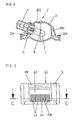
- FIG. 2 shows an embodiment of the license plate lamp (Z) in longitudinal section.
- the license plate light (Z) here has, for example, a housing (G), which can have locking means (RM), sealing means (DM) and ventilation openings (B ⁇ ).
- the housing which is preferably made of plastic, has a socket which contains a light source (L).
- L light source
- the housing (G) of the license plate lamp (Z) is closed off by a lens (S).
- the lens (S) is here curved, for example, in the longitudinal direction.
- the focal point (B) of the light source (L) is also identified in FIG.
- the optically active elements of the lens (S) are not shown in this figure.
- Figure 3 shows an embodiment of a lens (S).
- the lens (S) has three sections (A1, A2, A3) in the area through which the light is to be directed onto the license plate (KS).
- the first section (A1) has, for example, four cylindrical lenses (LI) and / or barrel lenses (LI), the first section (A1) being arranged in the area of the license plate lamp (Z) that is closest to the license plate (KS) .
- These lenses which are designed as cylindrical lenses (LI) and / or barrel lenses (LI), direct the incident light broadly into the side areas of the license plate (KS).
- the cylindrical lenses (LI) and / or barrel lenses (LI) are overlaid by prisms (PR) which run radially to the symmetry axes of the cylindrical lenses (LI) and / or barrel lenses (LI) and which direct the incident light in the direction of a first region (D1) Scatter the license plate (KS) that is close to the license plate light (Z).
- the lens (S) has here, for example, a second section (A2) with here, for example, in the longitudinal direction of the lens (S), that is to say, prisms (PP) running perpendicular to the axes of symmetry of the cylindrical lenses (LI) and / or barrel lenses (LI) which scatter the incident light into a second, more distant area (D2) of the license plate, which is not obvious to the license plate lamp (Z).
- PP prisms
- D2 second, more distant area of the license plate
- the lens (S) has a third section (A3) between the first section (A1) and the second section (A2), which is crystal clear or matt and has no optically effective elements and illuminates a third central area (D3) of the license plate (KS) with a basic brightness.
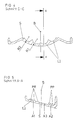
- Figure 4 shows a section CC of the lens (S) corresponding to Figure 3.
- the section CC runs through the area of the cylindrical lenses (LI) and / or barrel lenses (LI).
- the cylindrical lenses (LI) and / or barrel lenses (LI) and / or barrel lenses (LI) lying inside on the number of cylinder lenses (LI) and / or barrel lenses (LI) shown here as an example have a first radius (R1) that is larger than the second radius (R2) of the outer cylindrical lenses (LI) and / or barrel lenses (LI), whereby the light falling on the first section (A1) is scattered to a greater extent into the lateral edge areas of the license plate (KS).
- the first radius (R1) and the second radius (R2) can vary depending on the specified requirements.
- the number of cylindrical lenses (LI) and / or barrel lenses (LI) can also vary depending on the different embodiments. As can be seen from FIG. 4, the cylindrical lenses (LI) and / or barrel lenses (LI) merge into one another in strongly pronounced connection areas, as a result of which especially in the area of the transition from an extremely strong deflection behavior is achieved between the inner lenses and the outer lenses. The deflection behavior is increased by the curvature of the lens (S) in the longitudinal direction.
- FIG. 5 shows a section AA of the lens (S) corresponding to FIG. 4.
- the lens (S) here has three sections (A1, A2, A3) by way of example, the third section (A3) between the first section (A1) and the second section (A2) is arranged.
- This third section (A3) which is intended to provide general background lighting for the license plate (KS) predominantly in the central area thereof, has no optically effective elements and is of crystal-clear or matt design.
- the second section (A2) has prisms (PP) which run perpendicular to the axes of symmetry of the cylindrical lenses (LI) and / or barrel lenses (LI) and scatter the incident light into the second area (D2) of the license plate.
- the perpendicular prisms (PP) here have the same design and thus the same imaging behavior, with the arrangement in relation to the focal point (B) of the license plate lamp (Z) the perpendicular prisms (PP) the light in overlapping areas of the Scatter the second area (D2) of the license plate.
- the number and design of the prisms running in the longitudinal direction can vary from application to application.
- the third section (A3) can be omitted and the lens (S) only has a first section (A1) and a second section (A2).
- the first section (A1) has a predetermined number of cylindrical lenses (LI) and / or barrel lenses (LI).
- FIG. 4 shows a section through a cylindrical lens (LI).
- the cylindrical lens (LI) is overlaid by radially extending prisms (PR) which scatter the incident light in the direction of the upper area of the license plate.
- the first section (A1) is closest to the license plate (KS).
- the radially extending prisms (PR) scatter with increasing proximity to the number plate Edge of the lens (S) the incident light more towards the license plate (KS).
- the radially extending prisms (PR) are designed here, for example, towards the edge of the lens (S) with increasing scattering strength.
- the radially extending prisms (PR) each have the same design here, so that the radial prisms (F) of the light source (L) are arranged in the first region (D1) of the license plate (KS) due to the arrangement of the radially extending prisms. Overlapping areas of the illumination result, which leads to a high uniformity of the illumination.
- the number of radially extending prisms (PR) may differ from the number shown here.
- the size of the sections shown (A1, A2, A3) can vary.
- the scattering behavior of the radial prisms (PR) and their arrangement can vary.
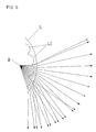
- Figure 6 shows an example of a beam path through the first section (A1) of a lens (S) corresponding to the section (CC), as shown in Figure 4.
- the fact that the inner cylindrical lenses (LI) and / or barrel lenses (LI) have a larger radius than that outer cylindrical lenses (LI) and / or barrel lenses (LI) and due to the extreme transition areas between the inner cylindrical lenses (LI) and / or barrel lenses (LI) and the outer cylindrical lenses (LI) and / or barrel lenses (LI) a larger part of the Light is deflected from the light source (L), the focal point (B) of which is shown here, into the more distant side areas of the license plate (KS), which is not shown here, which means that the license plate light (Z) is extremely close to the license plate (KS) a high uniformity in the illumination of the first area (D1) of the license plate (KS) is achieved.
- FIG. 7 shows a first example of illumination of a license plate (KS).
- the height of the license plate (KS) is only slightly less than its length. With such a license plate (KS), if the license plate lamp (Z) is in an extremely close position, a single license plate lamp (Z) is sufficient to illuminate the license plate (KS).
- the license plate lamp (Z) can be arranged above or below the license plate (KS).
- the first section (A1) of the lens (S) that is closest to the license plate (KS) illuminates, for example, the first area (D1), which is the upper area of the license plate (KS), for example.
- the second section (A2) of the lens (S) illuminates here, for example, the second, more distant lower region (D2) of the license plate (KS).
- the third section (A3) illuminates, if present, the third central area (D3) of the License plate (KS).
- the areas (D1, D2, D3) overlap.
- a third section (A3) is not present on the lens (S)
- the first area (D1) and the second area (D2) overlap.
- the individual areas (D1, D2, D3) can have different sizes, in addition the dividing lines and the overlay areas can look different from what is shown here by way of example.
- the transition areas can run in curved lines.
- Figure 8 shows an embodiment of a license plate (KS) with a large longitudinal extent.
- KS license plate
- the license plate lights (Z) illuminate three regions (D1, D2, D3) shown by way of example. Otherwise, the same statements apply as for FIG. 7.
Landscapes
- Engineering & Computer Science (AREA)
- Mechanical Engineering (AREA)
- Lighting Device Outwards From Vehicle And Optical Signal (AREA)
- Non-Portable Lighting Devices Or Systems Thereof (AREA)
Applications Claiming Priority (2)
| Application Number | Priority Date | Filing Date | Title |
|---|---|---|---|
| DE19904013503 DE4013503A1 (de) | 1990-04-27 | 1990-04-27 | Kennzeichenleuchte fuer kraftfahrzeuge |
| DE4013503 | 1990-04-27 |
Publications (2)
| Publication Number | Publication Date |
|---|---|
| EP0453887A1 true EP0453887A1 (fr) | 1991-10-30 |
| EP0453887B1 EP0453887B1 (fr) | 1994-10-05 |
Family
ID=6405242
Family Applications (1)
| Application Number | Title | Priority Date | Filing Date |
|---|---|---|---|
| EP19910105755 Expired - Lifetime EP0453887B1 (fr) | 1990-04-27 | 1991-04-11 | Feu pour plaque d'immatriculation de véhicule |
Country Status (4)
| Country | Link |
|---|---|
| EP (1) | EP0453887B1 (fr) |
| AU (1) | AU644154B2 (fr) |
| DE (1) | DE4013503A1 (fr) |
| ES (1) | ES2061101T3 (fr) |
Cited By (6)
| Publication number | Priority date | Publication date | Assignee | Title |
|---|---|---|---|---|
| GB2322932A (en) * | 1997-03-04 | 1998-09-09 | Koito Mfg Co Ltd | Light for illuminating vehicle number plate |
| US6814477B2 (en) * | 2001-09-17 | 2004-11-09 | Honda Giken Kogyo Kabushiki Kaisha | License light |
| DE102008025013A1 (de) | 2007-08-02 | 2009-02-05 | Zizala Lichtsysteme Gmbh | Optikelement zur Beleuchtung eines Fahrzeugkennzeichens |
| EP1920973A3 (fr) * | 2006-11-10 | 2009-06-03 | Maier, S. Coop. | Système d'éclairage pour plaque d'immatriculation d'automobile |
| CN104718108A (zh) * | 2012-10-10 | 2015-06-17 | 奥迪股份公司 | 用于机动车的后牌照板的照明装置 |
| CN110220161A (zh) * | 2018-03-01 | 2019-09-10 | 法雷奥市光(中国)车灯有限公司 | 配光装置、用于机动车辆的牌照灯以及机动车辆 |
Families Citing this family (2)
| Publication number | Priority date | Publication date | Assignee | Title |
|---|---|---|---|---|
| DE19961875C2 (de) * | 1999-12-22 | 2001-10-25 | Audi Ag | Kennzeichenleuchte |
| DE102007046197B4 (de) | 2007-09-26 | 2018-03-01 | HELLA GmbH & Co. KGaA | Signalleuchte für Kraftfahrzeuge |
Citations (1)
| Publication number | Priority date | Publication date | Assignee | Title |
|---|---|---|---|---|
| US4868723A (en) * | 1986-11-28 | 1989-09-19 | Koito Manufacturing Co., Ltd. | Car number plate lamp |
Family Cites Families (6)
| Publication number | Priority date | Publication date | Assignee | Title |
|---|---|---|---|---|
| DE1067321B (de) * | 1959-10-15 | Westfälische Metall-Industrie G.m. b.H. Lippstadt, Lippstadt | Kennzeichenrückleuchte für Kraftfahrzeuge | |
| DE1101983B (de) * | 1957-07-01 | 1961-03-09 | Reitter & Schefenacker | Kennzeichenleuchte, insbesondere fuer Kraftfahrzeuge |
| DE1898310U (de) * | 1963-05-03 | 1964-08-06 | Westfaelische Metall Ind K G H | Seitlich vom kennzeichenschild angeordnete leuchte fuer kraftfahrzeuge. |
| DE1655760B2 (de) * | 1967-01-20 | 1971-08-19 | Westfälische Metall Industrie KG Hueck & Co, 4780 Lippstadt | Kennzeichenleuchte fuer kraftfahrzeuge |
| US4255887A (en) * | 1978-07-28 | 1981-03-17 | Nihon Number Plate Kabushiki Kaisha | Illuminant display device and motor license plate using same |
| DE8202901U1 (de) * | 1982-02-04 | 1982-06-03 | Johann & Konen GmbH & Co, 5300 Bonn | Kennzeichenleuchte fuer strassenfahrzeuge und dergleichen |
-
1990
- 1990-04-27 DE DE19904013503 patent/DE4013503A1/de active Granted
-
1991
- 1991-04-11 EP EP19910105755 patent/EP0453887B1/fr not_active Expired - Lifetime
- 1991-04-11 ES ES91105755T patent/ES2061101T3/es not_active Expired - Lifetime
- 1991-04-24 AU AU75340/91A patent/AU644154B2/en not_active Ceased
Patent Citations (1)
| Publication number | Priority date | Publication date | Assignee | Title |
|---|---|---|---|---|
| US4868723A (en) * | 1986-11-28 | 1989-09-19 | Koito Manufacturing Co., Ltd. | Car number plate lamp |
Cited By (10)
| Publication number | Priority date | Publication date | Assignee | Title |
|---|---|---|---|---|
| GB2322932A (en) * | 1997-03-04 | 1998-09-09 | Koito Mfg Co Ltd | Light for illuminating vehicle number plate |
| US6109771A (en) * | 1997-03-04 | 2000-08-29 | Koito Manufacturing Co., Ltd. | License plate lamp |
| GB2322932B (en) * | 1997-03-04 | 2000-10-04 | Koito Mfg Co Ltd | License plate lamp |
| US6814477B2 (en) * | 2001-09-17 | 2004-11-09 | Honda Giken Kogyo Kabushiki Kaisha | License light |
| EP1920973A3 (fr) * | 2006-11-10 | 2009-06-03 | Maier, S. Coop. | Système d'éclairage pour plaque d'immatriculation d'automobile |
| DE102008025013A1 (de) | 2007-08-02 | 2009-02-05 | Zizala Lichtsysteme Gmbh | Optikelement zur Beleuchtung eines Fahrzeugkennzeichens |
| AT505529B1 (de) * | 2007-08-02 | 2009-06-15 | Zizala Lichtsysteme Gmbh | Optikelement zur beleuchtung eines fahrzeugkennzeichens |
| CN104718108A (zh) * | 2012-10-10 | 2015-06-17 | 奥迪股份公司 | 用于机动车的后牌照板的照明装置 |
| CN104718108B (zh) * | 2012-10-10 | 2018-02-02 | 奥迪股份公司 | 用于机动车的后牌照板的照明装置 |
| CN110220161A (zh) * | 2018-03-01 | 2019-09-10 | 法雷奥市光(中国)车灯有限公司 | 配光装置、用于机动车辆的牌照灯以及机动车辆 |
Also Published As
| Publication number | Publication date |
|---|---|
| AU7534091A (en) | 1991-11-07 |
| DE4013503C2 (fr) | 1992-02-06 |
| DE4013503A1 (de) | 1991-10-31 |
| EP0453887B1 (fr) | 1994-10-05 |
| ES2061101T3 (es) | 1994-12-01 |
| AU644154B2 (en) | 1993-12-02 |
Similar Documents
| Publication | Publication Date | Title |
|---|---|---|
| DE60026689T2 (de) | Beleuchtungsanlagen für kraftfahrzeuge | |
| DE69608044T2 (de) | Leuchte | |
| EP0900694A2 (fr) | Feu de signalisation pour véhicule | |
| EP0453887B1 (fr) | Feu pour plaque d'immatriculation de véhicule | |
| AT402627B (de) | Nummerntafel mit leuchtkennzeichen nummerntafel mit leuchtkennzeichen | |
| DE69636270T2 (de) | Zonenbildende Lichtverteilungslinse für Fahrzeugscheinwerfer | |
| DE2458427A1 (de) | Lochmaske fuer eine farbbildroehre | |
| DE2453234C3 (de) | Fahrzeugleuchte | |
| DE20012173U1 (de) | Leuchte | |
| DE3406876C1 (de) | Abgeblendeter Fahrzeugscheinwerfer | |
| EP0404990B1 (fr) | Feu pour véhicule | |
| DE102022111039A1 (de) | Lichtmodul mit mehreren Vorsatzoptiken | |
| EP1241094B1 (fr) | Feu de balisage encastré pour surfaces de circulation, notamment pour aéroports | |
| DE3019419A1 (de) | Beleuchtungsvorrichtung fuer anzeigeanordnung | |
| DE19750494A1 (de) | Scheinwerfer für Fahrzeuge | |
| DE60034169T2 (de) | Kfz-Lampe zur Beleuchtung des Kennzeichenschildes oder Richtungsanzeige | |
| DE2144588A1 (de) | Beleuchtung fuer kontroll- oder bedienungselemente von fahrzeugen | |
| DE3103175C2 (de) | Rückfahrscheinwerfer für Kraftfahrzeuge | |
| DE10153756A1 (de) | Leuchte mit segmentiertem Innenreflektor | |
| DE3933411C2 (fr) | ||
| EP0669493B1 (fr) | Feu clignotant | |
| DE2936192C2 (de) | Beleuchtbare Drucktaste, insbesondere für Kraftwagen | |
| EP0602374B1 (fr) | Feu pour véhicule automobile | |
| DE3742191C2 (fr) | ||
| DE69624754T2 (de) | Kfz-Multifunktionssignalleuchte mit Rückstrahlern und Pseudorückstrahlern |
Legal Events
| Date | Code | Title | Description |
|---|---|---|---|
| PUAI | Public reference made under article 153(3) epc to a published international application that has entered the european phase |
Free format text: ORIGINAL CODE: 0009012 |
|
| AK | Designated contracting states |
Kind code of ref document: A1 Designated state(s): AT ES FR GB IT NL SE |
|
| 17P | Request for examination filed |
Effective date: 19920408 |
|
| 17Q | First examination report despatched |
Effective date: 19931018 |
|
| GRAA | (expected) grant |
Free format text: ORIGINAL CODE: 0009210 |
|
| AK | Designated contracting states |
Kind code of ref document: B1 Designated state(s): ES FR GB IT |
|
| ITF | It: translation for a ep patent filed | ||
| REG | Reference to a national code |
Ref country code: ES Ref legal event code: FG2A Ref document number: 2061101 Country of ref document: ES Kind code of ref document: T3 |
|
| ET | Fr: translation filed | ||
| GBT | Gb: translation of ep patent filed (gb section 77(6)(a)/1977) |
Effective date: 19950105 |
|
| PG25 | Lapsed in a contracting state [announced via postgrant information from national office to epo] |
Ref country code: GB Effective date: 19950411 |
|
| PLBE | No opposition filed within time limit |
Free format text: ORIGINAL CODE: 0009261 |
|
| STAA | Information on the status of an ep patent application or granted ep patent |
Free format text: STATUS: NO OPPOSITION FILED WITHIN TIME LIMIT |
|
| 26N | No opposition filed | ||
| GBPC | Gb: european patent ceased through non-payment of renewal fee |
Effective date: 19950411 |
|
| PG25 | Lapsed in a contracting state [announced via postgrant information from national office to epo] |
Ref country code: FR Effective date: 19951229 |
|
| REG | Reference to a national code |
Ref country code: FR Ref legal event code: ST |
|
| PGFP | Annual fee paid to national office [announced via postgrant information from national office to epo] |
Ref country code: ES Payment date: 19970416 Year of fee payment: 7 |
|
| PG25 | Lapsed in a contracting state [announced via postgrant information from national office to epo] |
Ref country code: ES Free format text: LAPSE BECAUSE OF EXPIRATION OF PROTECTION Effective date: 19980413 |
|
| REG | Reference to a national code |
Ref country code: ES Ref legal event code: FD2A Effective date: 20000601 |
|
| PG25 | Lapsed in a contracting state [announced via postgrant information from national office to epo] |
Ref country code: IT Free format text: LAPSE BECAUSE OF NON-PAYMENT OF DUE FEES;WARNING: LAPSES OF ITALIAN PATENTS WITH EFFECTIVE DATE BEFORE 2007 MAY HAVE OCCURRED AT ANY TIME BEFORE 2007. THE CORRECT EFFECTIVE DATE MAY BE DIFFERENT FROM THE ONE RECORDED. Effective date: 20050411 |