EP0453928A2 - Hochfrequenzheizgerät - Google Patents
Hochfrequenzheizgerät Download PDFInfo
- Publication number
- EP0453928A2 EP0453928A2 EP91106064A EP91106064A EP0453928A2 EP 0453928 A2 EP0453928 A2 EP 0453928A2 EP 91106064 A EP91106064 A EP 91106064A EP 91106064 A EP91106064 A EP 91106064A EP 0453928 A2 EP0453928 A2 EP 0453928A2
- Authority
- EP
- European Patent Office
- Prior art keywords
- guide tube
- wave guide
- oven casing
- side wall
- high frequency
- Prior art date
- Legal status (The legal status is an assumption and is not a legal conclusion. Google has not performed a legal analysis and makes no representation as to the accuracy of the status listed.)
- Granted
Links
- 238000010438 heat treatment Methods 0.000 title claims description 26
- 230000005284 excitation Effects 0.000 claims abstract description 15
- 230000004907 flux Effects 0.000 description 5
- 238000010276 construction Methods 0.000 description 2
- 238000010411 cooking Methods 0.000 description 1
- 238000004519 manufacturing process Methods 0.000 description 1
- 230000004048 modification Effects 0.000 description 1
- 238000012986 modification Methods 0.000 description 1
Images
Classifications
-
- H—ELECTRICITY
- H05—ELECTRIC TECHNIQUES NOT OTHERWISE PROVIDED FOR
- H05B—ELECTRIC HEATING; ELECTRIC LIGHT SOURCES NOT OTHERWISE PROVIDED FOR; CIRCUIT ARRANGEMENTS FOR ELECTRIC LIGHT SOURCES, IN GENERAL
- H05B6/00—Heating by electric, magnetic or electromagnetic fields
- H05B6/64—Heating using microwaves
- H05B6/70—Feed lines
- H05B6/707—Feed lines using waveguides
Definitions
- the present invention relates generally to a high frequency heating apparatus that is called a microwave oven. More particularly, the present invention relates to a high frequency heating apparatus including a magnetron wherein a microwave generated by an antenna of the magnetron with a high frequency can effectively be conducted to the interior of a heating chamber through a wave guide tube having an improved structure.
- an oven casing 4 is arranged in the interior of a housing 1 and an instrument chamber 6 is installed on one side (right-hand side in the shown case) of the oven casing 4.
- the oven casing 4 is formed with an excitation aperture 7 on a side wall 4a of the oven casing 4 on the instrument chamber 6 side.
- a wave guide tube 8 is integrated with the side wall 4a of the oven casing 4 while extending across the excitation aperture 7.
- a magnetron 9 is arranged at the position substantially corresponding to the uppermost end of the wave guide tube 8 such that an antenna 9a of the magnetron 9 is protruded into the interior of the wave guide tube 8.
- a high voltage transformer 10 is installed on a bottom plate 1a of the housing 1 on the instrument chamber 6 side. As is apparent from the drawing, the transformer 10 is located below the wave guide tube 8 and the magnetron 9.
- a vibration proof rubber 11 is interposed between the transformer 10 and the side wall 4a of the oven casing 4 so as to absorb vibrations of the side wall 4a of the oven casing 4 induced by a leakage flux appearing instantaneously when the transformer 19 is activated by an electric current.
- the magnetron 9 is activated by an electric current to generate a microwave having a high frequency with the aid of an antenna 9a. Then, the microwave is conducted to the interior of the heating chamber 5 via the wave guide tube 8 and the excitation aperture 7, whereby a food W to be cooked is heated in the heating chamber 5.
- the wave guide tube 8 since the wave guide tube 8 is arranged in the space above the transformer 10, the wave guide tube 8 can not be constructed with a sufficiently long distance in the direction of propagation of the microwave. This leads to the result that the lower end of the wave guide tube 8 substantially coincides with the lower edge of the excitation aperture 7. For this reason, it is difficult to obtain proper impedance matching between the heating chamber 5 and the wave guide tube 8 and moreover there is a possibility that electric discharge occurs at the antenna 9a of the magnetron 9.
- the apparatus can not avoid vibrations induced by repeated magnetic pulling and pushing of the side wall 4a of the oven casing 4 due to the leakage flux appearing instantaneously when the transformer 10 is activated by an electric current. Therefore, the vibration proof rubber 11 should be interposed between the transformer 10 and the side wall 4a of the oven casing 4 so as to absorb the vibrations.
- An object of the present invention is to provide a high frequency heating apparatus which assures that proper impedance matching can easily be obtained between a heating chamber and a wave guide tube.
- Another object of the present invention is to provide a high frequency heating apparatus which assures that an occurrence of vibration of the side wall of an oven casing due to a leakage flux appearing instantaneously when a high voltage transformer is activated by an electric current can reliably be prevented without any necessity for interposing a vibration proof rubber between the transformer and the side wall of the oven casing.
- the present invention provides a high frequency heating apparatus including an oven casing of which interior serves as a heating chamber, the oven casing being formed with an excitation aperture on a side wall thereof, and a wave guide tube integrated with the side wall of the oven casing while extending across the excitation aperture, wherein the apparatus is characterized in that the wave guide tube is integrally attached to the outer surface of the side wall of the oven casing within the range from the upper end to the lower end of the oven casing and that a high voltage transformer is installed on the bottom plate of a housing opposite to the wave guide tube such that it is located outside of the lower end part of the wave guide tube.
- the wave guide tube is integrally attached to the side wall of the oven casing while extending across the excitation aperture within the range from the upper end to the lower end of the oven casing.
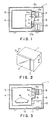
- Fig. 1 is a sectional front view of a high frequency heating apparatus in accordance with an embodiment of the present invention.
- Fig. 2 is a perspective view which shows an appearance of the high frequency heating apparatus in Fig. 1
- Fig. 3 is a sectional front view of a conventional high frequency heating apparatus.
- reference numeral 1 designates a housing which is constructed in the box-shaped configuration.
- An opening/closing door 2 and an control panel 3 are arranged on the front surface of the housing 1.
- an oven casing 4 is arranged in the housing 1 so as to allow the interior of the oven casing 4 to serve as a heating chamber 5.
- the housing 1 includes an instrument chamber 6 on one side (right-hand side in the shown case) of the housing 1
- the oven casing 4 is formed with an excitation aperture 7 on a side wall 4a of the oven casing 4 on the instrument chamber 6 side.
- a wave guide tube 12 is integrated with the side wall 4a of the oven casing 4 while extending across the excitation aperture 7 within the range from the upper and to the lower end of the oven casing 4 in the substantially vertical direction. Further, the apparatus is provided with a magnetron 9 at the position in the vicinity of the upper end 12a of the wave guide tube 12 such that an antenna 9a of the magnetron 9 is protruded into the interior of the wave guide tube 12 to generate a microwave having a high frequency.
- a vertical distance as measured from the center of the antenna 9a to the lower end 12b of the wave guide tube 12 is represented by D.
- this vertical distance D can be dimensioned longer than the vertical distance d of the conventional apparatus which has been described above with reference to Fig. 3.
- the dimenioning of the vertical distance D in that way makes it easier to obtain proper impedance matching between the heating chamber 5 and the wave guide tube 12 by adequately adjusting the vertical distance D.
- a high voltage transformer 10 is mounted on a bottom plate 1a of the housing 1 in the spaced relationship relative to the lower end 12b of the wave guide tube 12 with a certain distance therebetween.
- a height h of the wave guide tube 12 at the lower end 12b thereof is dimensioned smaller than a height H of the same at the upper end 12a, as shown in Fig. 1.
- the wave guide tube 12 is integrated with the side wall 4a of the oven casing 4 while extending across the excitation aperture 7 and a vertical distance as measured from the center of the excitation aperture 7 to the lower end 12b of the wave guide tube 12 is dimensioned sufficiently long.
- the construction of the apparatus as mentioned above makes it easier to obtain proper impedance matching between the heating chamber 5 and the wave guide tube 8.
- the wave guide tube 12 is integrated with the side wall 4a in that way, this assures that vibrations of the side wall 4a of the oven casing 4 induced by a leakage flux appearing instantaneously when the transformer 10 is activated by an electric current can reliably be absorbed by the apparatus.
Landscapes
- Physics & Mathematics (AREA)
- Electromagnetism (AREA)
- Constitution Of High-Frequency Heating (AREA)
- Electric Ovens (AREA)
Applications Claiming Priority (2)
| Application Number | Priority Date | Filing Date | Title |
|---|---|---|---|
| JP109531/90 | 1990-04-25 | ||
| JP2109531A JPH0410386A (ja) | 1990-04-25 | 1990-04-25 | 電子レンジ |
Publications (3)
| Publication Number | Publication Date |
|---|---|
| EP0453928A2 true EP0453928A2 (de) | 1991-10-30 |
| EP0453928A3 EP0453928A3 (en) | 1992-12-23 |
| EP0453928B1 EP0453928B1 (de) | 1995-10-04 |
Family
ID=14512617
Family Applications (1)
| Application Number | Title | Priority Date | Filing Date |
|---|---|---|---|
| EP91106064A Expired - Lifetime EP0453928B1 (de) | 1990-04-25 | 1991-04-16 | Hochfrequenzheizgerät |
Country Status (4)
| Country | Link |
|---|---|
| EP (1) | EP0453928B1 (de) |
| JP (1) | JPH0410386A (de) |
| KR (1) | KR910018732A (de) |
| DE (1) | DE69113503T2 (de) |
Cited By (1)
| Publication number | Priority date | Publication date | Assignee | Title |
|---|---|---|---|---|
| EP0585143A1 (de) * | 1992-08-25 | 1994-03-02 | Lg Electronics Inc. | Wellenleitersystem von einem Mikrowellenofen |
Family Cites Families (3)
| Publication number | Priority date | Publication date | Assignee | Title |
|---|---|---|---|---|
| JPS6136622A (ja) * | 1984-07-27 | 1986-02-21 | Matsushita Electric Ind Co Ltd | 高周波加熱装置 |
| DE3686735T2 (de) * | 1985-04-15 | 1993-01-28 | Matsushita Electric Ind Co Ltd | Hochfrequenzheizapparat mit elektrischem heizgeraet. |
| EP0373608B1 (de) * | 1988-12-14 | 1995-02-08 | Mitsubishi Denki Kabushiki Kaisha | Mikrowellenheizgerät |
-
1990
- 1990-04-25 JP JP2109531A patent/JPH0410386A/ja active Pending
-
1991
- 1991-04-16 EP EP91106064A patent/EP0453928B1/de not_active Expired - Lifetime
- 1991-04-16 DE DE69113503T patent/DE69113503T2/de not_active Expired - Fee Related
- 1991-04-24 KR KR1019910006698A patent/KR910018732A/ko not_active Ceased
Cited By (1)
| Publication number | Priority date | Publication date | Assignee | Title |
|---|---|---|---|---|
| EP0585143A1 (de) * | 1992-08-25 | 1994-03-02 | Lg Electronics Inc. | Wellenleitersystem von einem Mikrowellenofen |
Also Published As
| Publication number | Publication date |
|---|---|
| EP0453928A3 (en) | 1992-12-23 |
| EP0453928B1 (de) | 1995-10-04 |
| DE69113503D1 (de) | 1995-11-09 |
| KR910018732A (ko) | 1991-11-30 |
| JPH0410386A (ja) | 1992-01-14 |
| DE69113503T2 (de) | 1996-05-02 |
Similar Documents
| Publication | Publication Date | Title |
|---|---|---|
| US5942144A (en) | Door for microwave oven | |
| US4549054A (en) | Microwave oven construction having separate component receiving chambers | |
| EP0453928B1 (de) | Hochfrequenzheizgerät | |
| EP1503613B1 (de) | Mikrowellenofen | |
| GB2058529A (en) | Microwave heating apparatus | |
| KR19980063369A (ko) | 전자렌지 | |
| KR100652600B1 (ko) | 마이크로파를 이용한 조리기기 | |
| EP1021069B1 (de) | Mit einem Magnetfeldsensor versehenem Mikrowellenofen | |
| JP2614336B2 (ja) | 高周波加熱調理装置 | |
| US5600531A (en) | Capacitor for magnetron of microwave oven | |
| US5184104A (en) | Electromagnetic induction apparatus with a sound suppressing arrangement | |
| EP0648066B1 (de) | Enstörvorrichtung eines Magnetrons für einen Mikrowellenofen | |
| EP1363475B1 (de) | Mikrowellenofen | |
| EP1437923B1 (de) | Mikrowellenofen | |
| JP3192820B2 (ja) | 高周波加熱装置用ドア | |
| JPH07220866A (ja) | 電子レンジ | |
| KR100310366B1 (ko) | 전자렌지용 마그네트론 | |
| EP1515590B1 (de) | Mikrowellenofen mit reduziertem elektromagnetischem Rauschen | |
| US4855554A (en) | Arrangement in a microwave oven | |
| JPH0477433B2 (de) | ||
| KR100562103B1 (ko) | 전자레인지의 컨트롤판넬 결합구조 | |
| KR19990026290A (ko) | 전자렌지용 트랜스의 자장 차단장치 | |
| KR960006980B1 (ko) | 도파관 일체식 캐비티와 마그네트론의 취부구조 | |
| JPS60263018A (ja) | 高周波加熱装置 | |
| JPS5971286A (ja) | 高周波加熱装置 |
Legal Events
| Date | Code | Title | Description |
|---|---|---|---|
| PUAI | Public reference made under article 153(3) epc to a published international application that has entered the european phase |
Free format text: ORIGINAL CODE: 0009012 |
|
| 17P | Request for examination filed |
Effective date: 19910430 |
|
| AK | Designated contracting states |
Kind code of ref document: A2 Designated state(s): DE FR GB |
|
| PUAL | Search report despatched |
Free format text: ORIGINAL CODE: 0009013 |
|
| AK | Designated contracting states |
Kind code of ref document: A3 Designated state(s): DE FR GB |
|
| 17Q | First examination report despatched |
Effective date: 19940429 |
|
| GRAA | (expected) grant |
Free format text: ORIGINAL CODE: 0009210 |
|
| AK | Designated contracting states |
Kind code of ref document: B1 Designated state(s): DE FR GB |
|
| REF | Corresponds to: |
Ref document number: 69113503 Country of ref document: DE Date of ref document: 19951109 |
|
| ET | Fr: translation filed | ||
| PLBE | No opposition filed within time limit |
Free format text: ORIGINAL CODE: 0009261 |
|
| STAA | Information on the status of an ep patent application or granted ep patent |
Free format text: STATUS: NO OPPOSITION FILED WITHIN TIME LIMIT |
|
| 26N | No opposition filed | ||
| REG | Reference to a national code |
Ref country code: GB Ref legal event code: 746 Effective date: 19981010 |
|
| REG | Reference to a national code |
Ref country code: FR Ref legal event code: D6 |
|
| REG | Reference to a national code |
Ref country code: GB Ref legal event code: IF02 |
|
| PGFP | Annual fee paid to national office [announced via postgrant information from national office to epo] |
Ref country code: FR Payment date: 20030408 Year of fee payment: 13 |
|
| PGFP | Annual fee paid to national office [announced via postgrant information from national office to epo] |
Ref country code: GB Payment date: 20030416 Year of fee payment: 13 |
|
| PGFP | Annual fee paid to national office [announced via postgrant information from national office to epo] |
Ref country code: DE Payment date: 20030424 Year of fee payment: 13 |
|
| PG25 | Lapsed in a contracting state [announced via postgrant information from national office to epo] |
Ref country code: GB Free format text: LAPSE BECAUSE OF NON-PAYMENT OF DUE FEES Effective date: 20040416 |
|
| PG25 | Lapsed in a contracting state [announced via postgrant information from national office to epo] |
Ref country code: DE Free format text: LAPSE BECAUSE OF NON-PAYMENT OF DUE FEES Effective date: 20041103 |
|
| GBPC | Gb: european patent ceased through non-payment of renewal fee |
Effective date: 20040416 |
|
| PG25 | Lapsed in a contracting state [announced via postgrant information from national office to epo] |
Ref country code: FR Free format text: LAPSE BECAUSE OF NON-PAYMENT OF DUE FEES Effective date: 20041231 |
|
| REG | Reference to a national code |
Ref country code: FR Ref legal event code: ST |