EP0453944B1 - Système catalytique et procédé de préparation du 1,2-dichloroethane par chloration de l'éthylène en présence de ce système catalytique - Google Patents
Système catalytique et procédé de préparation du 1,2-dichloroethane par chloration de l'éthylène en présence de ce système catalytique Download PDFInfo
- Publication number
- EP0453944B1 EP0453944B1 EP91106153A EP91106153A EP0453944B1 EP 0453944 B1 EP0453944 B1 EP 0453944B1 EP 91106153 A EP91106153 A EP 91106153A EP 91106153 A EP91106153 A EP 91106153A EP 0453944 B1 EP0453944 B1 EP 0453944B1
- Authority
- EP
- European Patent Office
- Prior art keywords
- reaction
- catalyst system
- chloride
- temperature
- ethylene
- Prior art date
- Legal status (The legal status is an assumption and is not a legal conclusion. Google has not performed a legal analysis and makes no representation as to the accuracy of the status listed.)
- Expired - Lifetime
Links
- WSLDOOZREJYCGB-UHFFFAOYSA-N 1,2-Dichloroethane Chemical compound ClCCCl WSLDOOZREJYCGB-UHFFFAOYSA-N 0.000 title claims description 76
- VGGSQFUCUMXWEO-UHFFFAOYSA-N Ethene Chemical compound C=C VGGSQFUCUMXWEO-UHFFFAOYSA-N 0.000 title claims description 54
- 238000005660 chlorination reaction Methods 0.000 title claims description 30
- 238000002360 preparation method Methods 0.000 title claims description 11
- 230000003197 catalytic effect Effects 0.000 title description 3
- 238000006243 chemical reaction Methods 0.000 claims description 96
- 239000003054 catalyst Substances 0.000 claims description 68
- 239000000460 chlorine Substances 0.000 claims description 53
- 239000005977 Ethylene Substances 0.000 claims description 52
- RBTARNINKXHZNM-UHFFFAOYSA-K iron trichloride Chemical compound Cl[Fe](Cl)Cl RBTARNINKXHZNM-UHFFFAOYSA-K 0.000 claims description 51
- 229910021578 Iron(III) chloride Inorganic materials 0.000 claims description 42
- QWVGKYWNOKOFNN-UHFFFAOYSA-N o-cresol Chemical compound CC1=CC=CC=C1O QWVGKYWNOKOFNN-UHFFFAOYSA-N 0.000 claims description 38
- 238000000034 method Methods 0.000 claims description 35
- FAPWRFPIFSIZLT-UHFFFAOYSA-M Sodium chloride Chemical compound [Na+].[Cl-] FAPWRFPIFSIZLT-UHFFFAOYSA-M 0.000 claims description 33
- ZAMOUSCENKQFHK-UHFFFAOYSA-N Chlorine atom Chemical compound [Cl] ZAMOUSCENKQFHK-UHFFFAOYSA-N 0.000 claims description 29
- 229910052801 chlorine Inorganic materials 0.000 claims description 28
- 239000012429 reaction media Substances 0.000 claims description 27
- VEXZGXHMUGYJMC-UHFFFAOYSA-M Chloride anion Chemical compound [Cl-] VEXZGXHMUGYJMC-UHFFFAOYSA-M 0.000 claims description 20
- 239000000203 mixture Substances 0.000 claims description 17
- XLYOFNOQVPJJNP-UHFFFAOYSA-N water Substances O XLYOFNOQVPJJNP-UHFFFAOYSA-N 0.000 claims description 17
- 239000011780 sodium chloride Substances 0.000 claims description 16
- 238000009835 boiling Methods 0.000 claims description 15
- 239000007789 gas Substances 0.000 claims description 15
- VEXZGXHMUGYJMC-UHFFFAOYSA-N Hydrochloric acid Chemical compound Cl VEXZGXHMUGYJMC-UHFFFAOYSA-N 0.000 claims description 14
- 229910000041 hydrogen chloride Inorganic materials 0.000 claims description 14
- IXCSERBJSXMMFS-UHFFFAOYSA-N hydrogen chloride Substances Cl.Cl IXCSERBJSXMMFS-UHFFFAOYSA-N 0.000 claims description 14
- 239000007788 liquid Substances 0.000 claims description 14
- 238000010992 reflux Methods 0.000 claims description 14
- QVGXLLKOCUKJST-UHFFFAOYSA-N atomic oxygen Chemical compound [O] QVGXLLKOCUKJST-UHFFFAOYSA-N 0.000 claims description 12
- 239000001301 oxygen Substances 0.000 claims description 12
- 229910052760 oxygen Inorganic materials 0.000 claims description 12
- 239000006227 byproduct Substances 0.000 claims description 10
- 238000002156 mixing Methods 0.000 claims description 10
- 150000002989 phenols Chemical class 0.000 claims description 9
- VSCWAEJMTAWNJL-UHFFFAOYSA-K aluminium trichloride Chemical compound Cl[Al](Cl)Cl VSCWAEJMTAWNJL-UHFFFAOYSA-K 0.000 claims description 8
- 230000015572 biosynthetic process Effects 0.000 claims description 8
- 238000009833 condensation Methods 0.000 claims description 8
- 230000005494 condensation Effects 0.000 claims description 8
- 239000003112 inhibitor Substances 0.000 claims description 8
- 239000000047 product Substances 0.000 claims description 7
- KZBUYRJDOAKODT-UHFFFAOYSA-N Chlorine Chemical compound ClCl KZBUYRJDOAKODT-UHFFFAOYSA-N 0.000 claims description 6
- 125000004432 carbon atom Chemical group C* 0.000 claims description 6
- RLSSMJSEOOYNOY-UHFFFAOYSA-N m-cresol Chemical compound CC1=CC=CC(O)=C1 RLSSMJSEOOYNOY-UHFFFAOYSA-N 0.000 claims description 6
- 229940031826 phenolate Drugs 0.000 claims description 6
- 229910052751 metal Inorganic materials 0.000 claims description 5
- 239000002184 metal Substances 0.000 claims description 5
- IWDCLRJOBJJRNH-UHFFFAOYSA-N p-cresol Chemical compound CC1=CC=C(O)C=C1 IWDCLRJOBJJRNH-UHFFFAOYSA-N 0.000 claims description 5
- 229920006395 saturated elastomer Polymers 0.000 claims description 5
- UXVMQQNJUSDDNG-UHFFFAOYSA-L Calcium chloride Chemical compound [Cl-].[Cl-].[Ca+2] UXVMQQNJUSDDNG-UHFFFAOYSA-L 0.000 claims description 4
- 239000001110 calcium chloride Substances 0.000 claims description 4
- 229910001628 calcium chloride Inorganic materials 0.000 claims description 4
- 150000001768 cations Chemical class 0.000 claims description 4
- 238000001816 cooling Methods 0.000 claims description 4
- 125000004435 hydrogen atom Chemical group [H]* 0.000 claims description 4
- 150000002602 lanthanoids Chemical group 0.000 claims description 4
- 230000000737 periodic effect Effects 0.000 claims description 4
- -1 phenolate anion Chemical class 0.000 claims description 4
- 239000000376 reactant Substances 0.000 claims description 4
- 238000007086 side reaction Methods 0.000 claims description 4
- ONFAAMBUOAGWSG-UHFFFAOYSA-M sodium;2-methylphenolate Chemical compound [Na+].CC1=CC=CC=C1[O-] ONFAAMBUOAGWSG-UHFFFAOYSA-M 0.000 claims description 4
- UFHFLCQGNIYNRP-UHFFFAOYSA-N Hydrogen Chemical compound [H][H] UFHFLCQGNIYNRP-UHFFFAOYSA-N 0.000 claims description 3
- XEZSLVZJVPHXPK-UHFFFAOYSA-L [Ca+2].CC1=CC=C(O)C(C([O-])=O)=C1.CC1=CC=C(O)C(C([O-])=O)=C1 Chemical compound [Ca+2].CC1=CC=C(O)C(C([O-])=O)=C1.CC1=CC=C(O)C(C([O-])=O)=C1 XEZSLVZJVPHXPK-UHFFFAOYSA-L 0.000 claims description 3
- 229910052799 carbon Inorganic materials 0.000 claims description 3
- 150000008280 chlorinated hydrocarbons Chemical class 0.000 claims description 3
- 238000001704 evaporation Methods 0.000 claims description 3
- 229910052736 halogen Inorganic materials 0.000 claims description 3
- 150000002367 halogens Chemical class 0.000 claims description 3
- 239000001257 hydrogen Substances 0.000 claims description 3
- 229910052739 hydrogen Inorganic materials 0.000 claims description 3
- 125000002887 hydroxy group Chemical group [H]O* 0.000 claims description 3
- 239000002904 solvent Substances 0.000 claims description 3
- 125000003545 alkoxy group Chemical group 0.000 claims description 2
- 125000000217 alkyl group Chemical group 0.000 claims description 2
- 125000001309 chloro group Chemical group Cl* 0.000 claims description 2
- 230000008020 evaporation Effects 0.000 claims description 2
- ISWSIDIOOBJBQZ-UHFFFAOYSA-M phenolate Chemical compound [O-]C1=CC=CC=C1 ISWSIDIOOBJBQZ-UHFFFAOYSA-M 0.000 claims description 2
- 230000035484 reaction time Effects 0.000 claims description 2
- WYXVEAQHHQHGFH-UHFFFAOYSA-K [Ce+3].CC1=C(O)C=CC=C1C([O-])=O.CC1=C(O)C=CC=C1C([O-])=O.CC1=C(O)C=CC=C1C([O-])=O Chemical compound [Ce+3].CC1=C(O)C=CC=C1C([O-])=O.CC1=C(O)C=CC=C1C([O-])=O.CC1=C(O)C=CC=C1C([O-])=O WYXVEAQHHQHGFH-UHFFFAOYSA-K 0.000 claims 1
- 150000001875 compounds Chemical class 0.000 claims 1
- 229940100630 metacresol Drugs 0.000 claims 1
- XEEYBQQBJWHFJM-UHFFFAOYSA-N Iron Chemical compound [Fe] XEEYBQQBJWHFJM-UHFFFAOYSA-N 0.000 description 22
- 235000002639 sodium chloride Nutrition 0.000 description 17
- 238000005260 corrosion Methods 0.000 description 14
- 230000007797 corrosion Effects 0.000 description 14
- UBOXGVDOUJQMTN-UHFFFAOYSA-N 1,1,2-trichloroethane Chemical compound ClCC(Cl)Cl UBOXGVDOUJQMTN-UHFFFAOYSA-N 0.000 description 11
- 229910052742 iron Inorganic materials 0.000 description 11
- IJGRMHOSHXDMSA-UHFFFAOYSA-N Atomic nitrogen Chemical compound N#N IJGRMHOSHXDMSA-UHFFFAOYSA-N 0.000 description 10
- 239000003513 alkali Substances 0.000 description 8
- HRYZWHHZPQKTII-UHFFFAOYSA-N chloroethane Chemical compound CCCl HRYZWHHZPQKTII-UHFFFAOYSA-N 0.000 description 8
- 238000004519 manufacturing process Methods 0.000 description 7
- NLXLAEXVIDQMFP-UHFFFAOYSA-N Ammonia chloride Chemical compound [NH4+].[Cl-] NLXLAEXVIDQMFP-UHFFFAOYSA-N 0.000 description 6
- 150000001805 chlorine compounds Chemical class 0.000 description 6
- 229960003750 ethyl chloride Drugs 0.000 description 6
- 238000012360 testing method Methods 0.000 description 6
- 239000011521 glass Substances 0.000 description 5
- 239000000463 material Substances 0.000 description 5
- 229910052757 nitrogen Inorganic materials 0.000 description 5
- 230000002829 reductive effect Effects 0.000 description 5
- GHMLBKRAJCXXBS-UHFFFAOYSA-N resorcinol Chemical compound OC1=CC=CC(O)=C1 GHMLBKRAJCXXBS-UHFFFAOYSA-N 0.000 description 5
- RWNKSTSCBHKHTB-UHFFFAOYSA-N Hexachloro-1,3-butadiene Chemical compound ClC(Cl)=C(Cl)C(Cl)=C(Cl)Cl RWNKSTSCBHKHTB-UHFFFAOYSA-N 0.000 description 4
- BZHJMEDXRYGGRV-UHFFFAOYSA-N Vinyl chloride Chemical compound ClC=C BZHJMEDXRYGGRV-UHFFFAOYSA-N 0.000 description 4
- 235000019270 ammonium chloride Nutrition 0.000 description 4
- 239000007795 chemical reaction product Substances 0.000 description 4
- 239000000498 cooling water Substances 0.000 description 4
- 230000000694 effects Effects 0.000 description 4
- 238000011065 in-situ storage Methods 0.000 description 4
- ISWSIDIOOBJBQZ-UHFFFAOYSA-N phenol group Chemical group C1(=CC=CC=C1)O ISWSIDIOOBJBQZ-UHFFFAOYSA-N 0.000 description 4
- QGZKDVFQNNGYKY-UHFFFAOYSA-O Ammonium Chemical compound [NH4+] QGZKDVFQNNGYKY-UHFFFAOYSA-O 0.000 description 3
- 150000001412 amines Chemical class 0.000 description 3
- 125000004429 atom Chemical group 0.000 description 3
- 239000002585 base Substances 0.000 description 3
- 235000011148 calcium chloride Nutrition 0.000 description 3
- 238000004140 cleaning Methods 0.000 description 3
- 238000002474 experimental method Methods 0.000 description 3
- 229910001510 metal chloride Inorganic materials 0.000 description 3
- 238000012856 packing Methods 0.000 description 3
- 230000036961 partial effect Effects 0.000 description 3
- 238000000746 purification Methods 0.000 description 3
- 230000001105 regulatory effect Effects 0.000 description 3
- 229960001755 resorcinol Drugs 0.000 description 3
- 238000012546 transfer Methods 0.000 description 3
- QGZKDVFQNNGYKY-UHFFFAOYSA-N Ammonia Chemical compound N QGZKDVFQNNGYKY-UHFFFAOYSA-N 0.000 description 2
- KAKZBPTYRLMSJV-UHFFFAOYSA-N Butadiene Chemical compound C=CC=C KAKZBPTYRLMSJV-UHFFFAOYSA-N 0.000 description 2
- 101100116570 Caenorhabditis elegans cup-2 gene Proteins 0.000 description 2
- 229910004664 Cerium(III) chloride Inorganic materials 0.000 description 2
- 101100116572 Drosophila melanogaster Der-1 gene Proteins 0.000 description 2
- QIGBRXMKCJKVMJ-UHFFFAOYSA-N Hydroquinone Chemical compound OC1=CC=C(O)C=C1 QIGBRXMKCJKVMJ-UHFFFAOYSA-N 0.000 description 2
- 238000009825 accumulation Methods 0.000 description 2
- 239000002253 acid Substances 0.000 description 2
- 239000000654 additive Substances 0.000 description 2
- 229910001514 alkali metal chloride Inorganic materials 0.000 description 2
- 229910001617 alkaline earth metal chloride Inorganic materials 0.000 description 2
- JHXKRIRFYBPWGE-UHFFFAOYSA-K bismuth chloride Chemical compound Cl[Bi](Cl)Cl JHXKRIRFYBPWGE-UHFFFAOYSA-K 0.000 description 2
- 239000011575 calcium Substances 0.000 description 2
- YCIMNLLNPGFGHC-UHFFFAOYSA-N catechol Chemical compound OC1=CC=CC=C1O YCIMNLLNPGFGHC-UHFFFAOYSA-N 0.000 description 2
- 239000000919 ceramic Substances 0.000 description 2
- VYLVYHXQOHJDJL-UHFFFAOYSA-K cerium trichloride Chemical compound Cl[Ce](Cl)Cl VYLVYHXQOHJDJL-UHFFFAOYSA-K 0.000 description 2
- 239000000470 constituent Substances 0.000 description 2
- 238000005336 cracking Methods 0.000 description 2
- 239000012043 crude product Substances 0.000 description 2
- 238000004821 distillation Methods 0.000 description 2
- 238000004817 gas chromatography Methods 0.000 description 2
- LHGVFZTZFXWLCP-UHFFFAOYSA-N guaiacol Chemical compound COC1=CC=CC=C1O LHGVFZTZFXWLCP-UHFFFAOYSA-N 0.000 description 2
- 238000010438 heat treatment Methods 0.000 description 2
- 239000012535 impurity Substances 0.000 description 2
- 229910052747 lanthanoid Inorganic materials 0.000 description 2
- 238000005191 phase separation Methods 0.000 description 2
- WQGWDDDVZFFDIG-UHFFFAOYSA-N pyrogallol Chemical compound OC1=CC=CC(O)=C1O WQGWDDDVZFFDIG-UHFFFAOYSA-N 0.000 description 2
- 238000000197 pyrolysis Methods 0.000 description 2
- 238000011084 recovery Methods 0.000 description 2
- 238000004064 recycling Methods 0.000 description 2
- 230000002040 relaxant effect Effects 0.000 description 2
- 150000003839 salts Chemical class 0.000 description 2
- 238000006467 substitution reaction Methods 0.000 description 2
- SCYULBFZEHDVBN-UHFFFAOYSA-N 1,1-Dichloroethane Chemical compound CC(Cl)Cl SCYULBFZEHDVBN-UHFFFAOYSA-N 0.000 description 1
- JFGVTUJBHHZRAB-UHFFFAOYSA-N 2,6-Di-tert-butyl-1,4-benzenediol Chemical compound CC(C)(C)C1=CC(O)=CC(C(C)(C)C)=C1O JFGVTUJBHHZRAB-UHFFFAOYSA-N 0.000 description 1
- NGFPWHGISWUQOI-UHFFFAOYSA-N 2-sec-butylphenol Chemical compound CCC(C)C1=CC=CC=C1O NGFPWHGISWUQOI-UHFFFAOYSA-N 0.000 description 1
- WXNZTHHGJRFXKQ-UHFFFAOYSA-N 4-chlorophenol Chemical compound OC1=CC=C(Cl)C=C1 WXNZTHHGJRFXKQ-UHFFFAOYSA-N 0.000 description 1
- OKTJSMMVPCPJKN-UHFFFAOYSA-N Carbon Chemical compound [C] OKTJSMMVPCPJKN-UHFFFAOYSA-N 0.000 description 1
- 229910052684 Cerium Inorganic materials 0.000 description 1
- DGAQECJNVWCQMB-PUAWFVPOSA-M Ilexoside XXIX Chemical compound C[C@@H]1CC[C@@]2(CC[C@@]3(C(=CC[C@H]4[C@]3(CC[C@@H]5[C@@]4(CC[C@@H](C5(C)C)OS(=O)(=O)[O-])C)C)[C@@H]2[C@]1(C)O)C)C(=O)O[C@H]6[C@@H]([C@H]([C@@H]([C@H](O6)CO)O)O)O.[Na+] DGAQECJNVWCQMB-PUAWFVPOSA-M 0.000 description 1
- 241001503485 Mammuthus Species 0.000 description 1
- JPYHHZQJCSQRJY-UHFFFAOYSA-N Phloroglucinol Natural products CCC=CCC=CCC=CCC=CCCCCC(=O)C1=C(O)C=C(O)C=C1O JPYHHZQJCSQRJY-UHFFFAOYSA-N 0.000 description 1
- ATJFFYVFTNAWJD-UHFFFAOYSA-N Tin Chemical compound [Sn] ATJFFYVFTNAWJD-UHFFFAOYSA-N 0.000 description 1
- RTAQQCXQSZGOHL-UHFFFAOYSA-N Titanium Chemical compound [Ti] RTAQQCXQSZGOHL-UHFFFAOYSA-N 0.000 description 1
- 150000007513 acids Chemical class 0.000 description 1
- 229910021529 ammonia Inorganic materials 0.000 description 1
- 125000003118 aryl group Chemical group 0.000 description 1
- 238000010533 azeotropic distillation Methods 0.000 description 1
- GGNQRNBDZQJCCN-UHFFFAOYSA-N benzene-1,2,4-triol Chemical compound OC1=CC=C(O)C(O)=C1 GGNQRNBDZQJCCN-UHFFFAOYSA-N 0.000 description 1
- 229910052797 bismuth Inorganic materials 0.000 description 1
- JCXGWMGPZLAOME-UHFFFAOYSA-N bismuth atom Chemical compound [Bi] JCXGWMGPZLAOME-UHFFFAOYSA-N 0.000 description 1
- GWXLDORMOJMVQZ-UHFFFAOYSA-N cerium Chemical compound [Ce] GWXLDORMOJMVQZ-UHFFFAOYSA-N 0.000 description 1
- 239000012295 chemical reaction liquid Substances 0.000 description 1
- 238000003776 cleavage reaction Methods 0.000 description 1
- 239000000571 coke Substances 0.000 description 1
- 238000010276 construction Methods 0.000 description 1
- 230000009849 deactivation Effects 0.000 description 1
- 238000000354 decomposition reaction Methods 0.000 description 1
- 238000013461 design Methods 0.000 description 1
- 230000008030 elimination Effects 0.000 description 1
- 238000003379 elimination reaction Methods 0.000 description 1
- 238000005265 energy consumption Methods 0.000 description 1
- 230000003628 erosive effect Effects 0.000 description 1
- 239000003517 fume Substances 0.000 description 1
- PCHJSUWPFVWCPO-UHFFFAOYSA-N gold Chemical compound [Au] PCHJSUWPFVWCPO-UHFFFAOYSA-N 0.000 description 1
- 239000010931 gold Substances 0.000 description 1
- 229910052737 gold Inorganic materials 0.000 description 1
- 229960001867 guaiacol Drugs 0.000 description 1
- 238000007038 hydrochlorination reaction Methods 0.000 description 1
- 229960004337 hydroquinone Drugs 0.000 description 1
- 230000001771 impaired effect Effects 0.000 description 1
- 230000002401 inhibitory effect Effects 0.000 description 1
- 239000003446 ligand Substances 0.000 description 1
- 239000007791 liquid phase Substances 0.000 description 1
- 239000007769 metal material Substances 0.000 description 1
- 239000002480 mineral oil Substances 0.000 description 1
- 239000000178 monomer Substances 0.000 description 1
- 230000009972 noncorrosive effect Effects 0.000 description 1
- 229940090668 parachlorophenol Drugs 0.000 description 1
- QCDYQQDYXPDABM-UHFFFAOYSA-N phloroglucinol Chemical compound OC1=CC(O)=CC(O)=C1 QCDYQQDYXPDABM-UHFFFAOYSA-N 0.000 description 1
- 229960001553 phloroglucinol Drugs 0.000 description 1
- 238000005086 pumping Methods 0.000 description 1
- 229940079877 pyrogallol Drugs 0.000 description 1
- 230000005855 radiation Effects 0.000 description 1
- 239000011541 reaction mixture Substances 0.000 description 1
- 230000007017 scission Effects 0.000 description 1
- 238000000926 separation method Methods 0.000 description 1
- 229910052708 sodium Inorganic materials 0.000 description 1
- 239000011734 sodium Substances 0.000 description 1
- 229910001220 stainless steel Inorganic materials 0.000 description 1
- 239000010935 stainless steel Substances 0.000 description 1
- 239000000725 suspension Substances 0.000 description 1
- 229910052714 tellurium Inorganic materials 0.000 description 1
- PORWMNRCUJJQNO-UHFFFAOYSA-N tellurium atom Chemical compound [Te] PORWMNRCUJJQNO-UHFFFAOYSA-N 0.000 description 1
- GBECUEIQVRDUKB-UHFFFAOYSA-M thallium monochloride Chemical compound [Tl]Cl GBECUEIQVRDUKB-UHFFFAOYSA-M 0.000 description 1
- 239000010936 titanium Substances 0.000 description 1
- 229910052719 titanium Inorganic materials 0.000 description 1
- 238000004448 titration Methods 0.000 description 1
- HCQLFHJKDCJBSQ-UHFFFAOYSA-K trichloroiron hydrochloride Chemical compound Cl.Cl[Fe](Cl)Cl HCQLFHJKDCJBSQ-UHFFFAOYSA-K 0.000 description 1
- WFKWXMTUELFFGS-UHFFFAOYSA-N tungsten Chemical compound [W] WFKWXMTUELFFGS-UHFFFAOYSA-N 0.000 description 1
- 229910052721 tungsten Inorganic materials 0.000 description 1
- 239000010937 tungsten Substances 0.000 description 1
- 238000005406 washing Methods 0.000 description 1
- 238000005303 weighing Methods 0.000 description 1
- 238000010626 work up procedure Methods 0.000 description 1
Images


Classifications
-
- B—PERFORMING OPERATIONS; TRANSPORTING
- B01—PHYSICAL OR CHEMICAL PROCESSES OR APPARATUS IN GENERAL
- B01J—CHEMICAL OR PHYSICAL PROCESSES, e.g. CATALYSIS OR COLLOID CHEMISTRY; THEIR RELEVANT APPARATUS
- B01J31/00—Catalysts comprising hydrides, coordination complexes or organic compounds
- B01J31/26—Catalysts comprising hydrides, coordination complexes or organic compounds containing in addition, inorganic metal compounds not provided for in groups B01J31/02 - B01J31/24
- B01J31/28—Catalysts comprising hydrides, coordination complexes or organic compounds containing in addition, inorganic metal compounds not provided for in groups B01J31/02 - B01J31/24 of the platinum group metals, iron group metals or copper
- B01J31/30—Halides
-
- B—PERFORMING OPERATIONS; TRANSPORTING
- B01—PHYSICAL OR CHEMICAL PROCESSES OR APPARATUS IN GENERAL
- B01J—CHEMICAL OR PHYSICAL PROCESSES, e.g. CATALYSIS OR COLLOID CHEMISTRY; THEIR RELEVANT APPARATUS
- B01J31/00—Catalysts comprising hydrides, coordination complexes or organic compounds
- B01J31/02—Catalysts comprising hydrides, coordination complexes or organic compounds containing organic compounds or metal hydrides
- B01J31/0201—Oxygen-containing compounds
- B01J31/0211—Oxygen-containing compounds with a metal-oxygen link
- B01J31/0214—Aryloxylates, e.g. phenolates
-
- C—CHEMISTRY; METALLURGY
- C07—ORGANIC CHEMISTRY
- C07C—ACYCLIC OR CARBOCYCLIC COMPOUNDS
- C07C17/00—Preparation of halogenated hydrocarbons
- C07C17/013—Preparation of halogenated hydrocarbons by addition of halogens
- C07C17/02—Preparation of halogenated hydrocarbons by addition of halogens to unsaturated hydrocarbons
-
- B—PERFORMING OPERATIONS; TRANSPORTING
- B01—PHYSICAL OR CHEMICAL PROCESSES OR APPARATUS IN GENERAL
- B01J—CHEMICAL OR PHYSICAL PROCESSES, e.g. CATALYSIS OR COLLOID CHEMISTRY; THEIR RELEVANT APPARATUS
- B01J2231/00—Catalytic reactions performed with catalysts classified in B01J31/00
- B01J2231/30—Addition reactions at carbon centres, i.e. to either C-C or C-X multiple bonds
- B01J2231/32—Addition reactions to C=C or C-C triple bonds
Definitions
- the invention relates to a catalyst system for the preparation of 1,2-dichloroethane by reaction between ethylene and chlorine, optionally in the presence of an inhibitor to reduce the formation of by-products, and a process for the preparation of 1,2-dichloroethane using this catalyst system.
- the ethylene chlorination is also carried out in the presence of oxygen as a substitution inhibitor (US-A 2601322, DE-A 1568583).
- the crude, catalyst-containing EDC produced at lower temperatures is usually drawn off liquid from the reactor and must be washed with acid water and then with aqueous alkali solutions to remove the catalyst in order to neutralize the crude product. After phase separation by decanting and separating the aqueous layer, the remaining water-saturated crude EDC is then worked up by distillation in a known manner, but in a complex manner.
- ethylene is chlorinated at temperatures from 100 to 130 ° C. and correspondingly high pressures, in order to be able to carry out the reaction in the liquid phase, in the presence of iron (III) chloride as a catalyst, and the mixture formed is reacted with the circulating reaction medium to a lower-pressure zone in which the crude EDC formed evaporates by the heat of reaction liberated in the reaction of chlorine with ethylene and is rectified by recycling high-boiling impurities into the reaction zone becomes. This leads to high boiler accumulation in the reaction cycle.
- EP-A 82342 iron-III-chloride catalyst in the presence of nitrogen bases, such as ammonia, amines, or salts of these bases
- EP-A 111203 alkali or alkaline earth tetrachloroferrate catalysts
- the corrosion caused by iron III chloride as a catalyst in EDC production in reactors which have been produced using conventional metallic materials can be considerably reduced if the iron III chloride is used -Catalyst with the additives mentioned there.
- these additives also have an advantageous effect on by-product formation, which is thereby reduced.
- EP-A 113287 teaches a process according to which in the presence of Iron III chloride at temperatures from 140 to 180 ° C about 85% of the heat of reaction released in ethylene chlorination can be used to generate steam.
- the EDC leaving the reaction zone is cooled by heat exchange with water before further work-up or recycling back into the reaction zone.
- many by-products also arise.
- the reaction mixture from the ethylene chlorination is divided into two partial streams, one of which is passed through a heat exchanger and then returns to the circuit, while the second partial stream is expanded and fed to a rectification column which is passed through the above Heat exchanger is heated.
- the flexibility just discussed is not given, so that in the event of deviations from the "balanced process", due to a lack of sufficient heat of reaction to be released, or due to an increased EDC production beyond the "balanced process", the high-boiling column integrated into the reaction system is additionally added heated with steam or, in the opposite case, excess reaction enthalpy must be dissipated into the cooling water or to the air via a trim cooler.
- Deviations from the "balanced process” occur, for example, if the ethylene chlorination has to be reduced due to a temporary lack of chlorine or if the excess supply of external hydrogen chloride increases the oxychlorination of ethylene or, in the normal driving style, the Direct chlorination the oxychlorination, due to reduced vinyl chloride monomer production, also runs lower.
- the object was therefore to develop a catalyst system for the production of 1,2-dichloroethane which, in all technically important temperature ranges, that is to say from 0 ° C. to 300 ° C., has an optimum selectivity or yield in the chlorination of ethylene. as well as a minimum of corrosion.
- this catalyst system was to transfer to a simple and economical process for the production of EDC by chlorination of ethylene, which, depending on the local conditions, makes it possible either to use at least a part of the released enthalpy of reaction for the purification of formed EDC in gap quality or practically that to utilize the entire reaction enthalpy released to generate steam at a technically sensible pressure, the catalyst system should remain in the reaction medium, and the EDC formed has to be freed from only small amounts of high-boiling impurities before use in a pyrolysis furnace.
- the catalyst system according to the invention is obtained by mixing together the component Me + n Cl n , that is to say hydrogen chloride gas and / or alkali metal chlorides and / or alkaline earth metal chlorides or chlorides of the lanthanides with the component Z + m Cl m , that is to say with metal chlorides of the elements of the third 4th, 5th or 6th main group or the 1st, 4th, 6th or 8th subgroup of the Periodic Table of the Elements, and with the phenolic compounds of the general formulas described above.
- the admixture is carried out in each case in almost equimolar amounts of Z + m Cl m and phenolic compound with one another, with a scattering range of 0.9 to 1.1: 1 equivalent proportions, as a solution or suspension, preferably in 1,2-dichloroethane.
- the equivalence between Me + n Cl n and phenolic compound can also have a range from 0.5 to 1.5: 1, preferably the range from 0.9 to 1.1: 1.
- the catalysts Me + n [Z + m Cl m ⁇ L] n according to the invention can be prepared from the mixture of Z + m Cl m , Me + n Cl n and the phenolic compound in a separate reaction step by mixing and, if appropriate, heating under reflux for several hours take place or in situ in the reaction zone of the ethylene chlorination reactor, after adding the mixture to the reaction medium.
- the core chlorination can be carried out separately in the EDC solution or in a separate catalyst agitator before mixing with the other constituents of the catalyst system.
- the core chlorination is preferably carried out in situ in the reaction zone of the ethylene chlorination reactor after the mixture of the individual catalyst components has been added.
- Sodium chloride or calcium chloride are preferably used as alkali and alkaline earth chlorides. Of the lanthanides, cerium III chloride is preferably used.
- the metal chlorides which supply the central atom Z of the phenolate chloro complex are preferably aluminum chloride, tin IV chloride, bismuth III chloride, tellurium IV chloride, gold III chloride, titanium IV chloride, tungsten VI chloride, thallium chloride. I-chloride and iron-III-chloride. Iron III chloride is particularly preferably used.
- Phenol is particularly suitable as phenolic compound; ortho, meta, para cresol; ortho-, meta-, para-chlorophenol; 2-sec-butylphenol, pyrocatechol, resorcinol, hydroquinone, guaiacol, pyrogallol, oxyhydroquinone, phloroglucinol and 3,5-di-tert-butylhydroquinone.
- catalysts are hydrogen metacresolate trichloroferrate, sodium ortho-cresolate trichloroferrate, calcium bis-para-cresolate trichloroaluminate and Certris ortho-cresolate trichloroaluminate, which can optionally be mono- or polynuclear.
- Suitable reactors for ethylene chlorination are loop reactors, such as those described in DE-A 2427045, or loop reactors according to DE-B 1768367 or according to the accompanying FIG. 1, or tower reactors according to the accompanying FIG. 2.
- the chlorination is carried out in a circulating circuit liquid medium consisting of chlorinated hydrocarbons with 2 carbon atoms. 1,2-dichloroethane is preferably used as the reaction medium.
- the speed of the circulating reaction medium is preferably between 0.1 and 5 m / s.
- the circulation of the liquid reaction medium in the reactor can be effected, for example, by means of a pump and / or according to the thermosiphon or mammoth pump principle.
- the reactor is charged with ethylene and chlorine, the molar ratio of ethylene to chlorine preferably being between 1: 1 and 1,005: 1.
- the gas velocity in the reaction space is preferably 0.01 to 1 m / s, based on the ethylene gas flow.
- the concentration of the catalyst system Me + n [Z + m Cl m ⁇ L] n dissolved or suspended in the reaction medium is between 0.01 and 1.0% by weight, preferably 0.2 to 0.7% by weight, in each case based on the amount of reaction medium and calculated as Z + m Cl m .
- the catalyst system in the form of the individual components is dissolved or suspended in the reaction medium, the individual components preferably being used in a molar ratio of from 0.9 to 1.1: 1 to one another.
- catalysts are hydrogen metacresolate trichloroferrate, sodium ortho-cresolate trichloroferrate, calcium bis-para-cresolate trichloroaluminate and Certris ortho-cresolate trichloroaluminate, which can optionally be mono- or polynuclear.
- sodium ortho-cresolate trichloro-ferrate preferably in a concentration of 0.3 to 0.5% by weight, based on the reaction medium, is used as the catalyst system. It is preferably formed in situ, after addition of an equimolar mixture of NaCl, FeCl3 and o-cresol to the reaction medium in the range of equivalence mentioned.
- the catalyst system is circulated with the reaction medium, replacing the used ethylene and chlorine.
- oxygen or air can optionally be used as an inhibitor.
- concentration is 0.01 to 10% by volume, preferably 0.8 to 1.5% by volume, each calculated as oxygen and based on the amount of chlorine gas.
- the average residence time of the reactant mixture is 0.2 to 2 minutes, based on the empty reaction, mixing and circulation space under normal conditions (0 ° C, 1013 mbar).
- the reaction time of the reactants in the reaction space is preferably between 1.5 and 60 seconds.
- the chlorination reaction is carried out at reaction temperatures between 0 and 300 ° C. and at pressures which prevent the reaction medium from boiling in the reaction space.
- the reaction temperature is 0 to 120 ° C, preferably 40 to 80 ° C, and the pressure in the reaction space is preferably between 1 and 5 bar absolute.
- the reaction temperature is 120 to 300 ° C., preferably 140 to 170 ° C., and the pressure in the reaction space is preferably between 5 and 10 bar absolute.
- the 1,2-dichloroethane is withdrawn from the reaction zone into a zone of lower pressure and the vapors formed are passed into a rectification column.
- the rectification column is preferably a packed column or a tray column.
- the number of theoretical plates is preferably between 1 and 5.
- the vapors are condensed at the top of the rectification column in a condenser by indirect heat exchange with water or air.
- the pressure at the top of the column is preferably 0.2 to 0.9 bar abs.
- a portion of the condensate is fed as a liquid reflux to the rectification column, the remaining amount is more or less supercooled, preferably at a temperature which is about 5 to 50 ° C. lower than the boiling temperature, is fed to the circulating reaction medium and returned to the reaction space.
- the minimum reflux ratio expressed as the weight ratio of reflux to the product produced, is preferably 2: 1 parts by weight.
- the 1,2-dichloroethane produced is taken off in the bottom of the rectification column.
- the remaining heat of reaction can be dissipated into the cooling water or into the air via a heat exchanger in the circulation circuit.
- the vapors are condensed in a heat exchanger at the top of the rectification column.
- the pressure at the top of the column is preferably 4.5 to 8.3 bar abs.
- Any heat transfer medium is conceivable as heat exchange media, for example mineral oils which give off the heat adsorbed at another point and are accordingly cooled and returned to the heat exchanger.
- the heat of condensation of the vapors is preferably used to produce saturated steam at a pressure of 2.25 to 6.0 bar abs., By heat exchange of the vapors of the rectification column with pressure corresponding to hot water.
- a portion of the condensate is fed as a liquid reflux to the rectification column, the remaining amount is fed to the circulating reaction medium and returned to the reaction space, the temperature of the vapor condensate returned to the reaction space being subcooled by a maximum of 5 ° C., based on the boiling point or condensation temperature.
- the minimum reflux ratio expressed as the weight ratio of reflux to the product produced, is preferably 1: 1 parts by weight.
- the non-condensable portions of the rectification column overhead are discharged into the atmosphere or into an incinerator.
- the 1,2-dichloroethane produced is taken off in the bottom of the rectification column.
- the recovery of the entire reaction enthalpy released in the ethylene chlorination is possible.
- the heat of the reaction is used entirely to generate the vaporous 1,2-dichloroethane by relaxing the reaction product and can be recovered as heat of condensation of the vapors by heat exchange.
- FIGS. 1 and 5 The method according to the invention and a device for ethylene chlorination in the low-temperature mode are shown by way of example in FIGS. 1 and 5.
- the method according to the invention and a device for the high-temperature mode of operation are shown as examples in FIGS. 2 and 6.
- the inventive method offers a number of advantages: Due to the removal of the reaction product from the reaction space in vapor form, the need for catalyst replenishment and catalyst removal from the crude product is eliminated. This is also the basis for the elimination of the environmentally friendly pretreatment of the washing water contaminated by EDC (eg removal of CHC by steam stripping). The process gives high yields with extremely low by-product formation (high selectivity). Because the catalyst system according to the invention is almost non-corrosive, therefore no exotic materials are required, and moreover the reaction apparatus is relatively simple and not very extensive, the apparatus costs are high also low in the high-temperature mode.
- the catalyst system according to the invention is clearly superior to all previously known catalyst mixtures for the direct chlorination of ethylene, both in terms of selectivity and in terms of corrosion behavior, this superiority only becoming clearly evident at elevated reaction temperatures.
- the catalyst system according to the invention has a far less corrosive effect than comparable catalyst mixtures according to the prior art, both in the low and high temperature mode, it can be seen that the catalyst system according to the invention must surprisingly be thermally very stable.
- Corrosion tests were carried out with various catalyst mixtures at 84 ° C (boiling point of EDC) and at 212 ° C (boiling point of hexachlorobutadiene).
- V4A stainless steel plates with the dimensions 40 x 20 x 2 mm were immersed in liquid EDC or hexachlorobutadiene.
- the liquid contained 5000 ppm by weight of iron (III) chloride or an equimolar mixture of ammonium chloride and iron (III) chloride or an equimolar mixture of sodium chloride and iron (III) chloride or an equimolar mixture of ortho-cresol and iron III chloride or an equimolar mixture of sodium chloride, ortho-cresol and iron III chloride, in each case in a concentration of 5000 ppm, calculated as iron III chloride, in dissolved or in suspended form.
- the corrosion rates were determined gravimetrically by differential weighing of the platelets. The results are summarized in Table 1.
- the vertical glass reaction tower (inside diameter 50 mm, height 300 mm) was filled with 2 mm Raschig rings and surrounded by a double jacket in which thermostated water at a temperature of 84 ° C was circulated. This additional heating was necessary despite the exothermic reaction between chlorine and ethylene to cover the heat loss through radiation (unfavorable ratio of surface area to heat release) so that EDC distilled out of the reactor.
- Reaction liquid was circulated at a rate of 0.6 cm / s in a quantity of 40 l / h via a metering pump over the reactor filled with glass Raschig rings.
- 40 Nl / h of chlorine and 250 Ncm3 / h of oxygen were introduced into the circulating reaction medium, while 40.2 Nl / h of ethylene were blown into the reactor from below through a glass frit in the reaction tower.
- the reactor was charged in each case with 500 cm 3 of EDC, in which the different catalyst systems produced in accordance with Example 2 were present in a concentration of 0.5% by weight as the dissolved or suspended metal chloride, which is the central atom of the respective catalyst complex.
- the distilled EDC was condensed in a water cooler and collected. 175 g / h of EDC produced were branched off and removed using a condensate divider, while excess condensate was returned to the reaction zone.
- a cold trap was used further EDC fraction from the exhaust gas stream - essentially oxygen, excess ethylene and nitrogen, which were fed in for the purpose of inerting in an amount of 2 Nl / h after the condenser.
- the combined EDC generated was examined for purity by gas chromatography.
- the exhaust gas from the cold trap was also examined by gas chromatography for low-boiling by-products and chlorine. Chlorine was not found in any of the experiments, ie the conversion was always quantitative.
- This EDC could be converted to vinyl chloride and hydrogen chloride directly in a cracking furnace without further purification, without the cracking kinetics or the by-product and coke formation being impaired in any way, such as an operational test, after appropriate amounts had previously been collected, of these EDCs produced by the process according to the invention had proven. Even after a 4-month trial, there was no loss of quality in the EDC produced or loss of catalyst. A high boiler accumulation in the reactor circuit was also not observed.
- the reactor R according to Figure 2 consisted of a vertical tower (diameter 200 mm, length 4000 mm), which was filled with a packing. Via line 23 and the heat exchanger H, which could be heated with steam in order to make the entire apparatus water-free by azeotropic distillation with EDC, 50 m3 / h EDC was circulated in a circle by means of the pump P1. In this circulation stream was FeCl3, NaCl and m-cresol in equimolar amounts to each other and in a concentration of 0.5 wt%, calculated as FeCl3, dissolved or suspended.
- the non-condensable exhaust gas flowed via line 30 to the cooler K, and any condensate was collected in the separator A2 and flowed back via line 31 to the separator A1.
- the exhaust gas was pressure-controlled to 7.05 bar absolute at 21 and discharged to an incinerator.
- the exhaust gas was analyzed for chlorine with the help of the analyzer AR. Via line 7, regulated from the level in the reaction tower, bottom product was removed from column F into the reaction system. Chlorine was not found in the AR analyzer. H. the chlorine conversion was quantitative.
- the catalyst system according to the invention was thermally stable.
Landscapes
- Chemical & Material Sciences (AREA)
- Organic Chemistry (AREA)
- Engineering & Computer Science (AREA)
- Materials Engineering (AREA)
- Chemical Kinetics & Catalysis (AREA)
- Inorganic Chemistry (AREA)
- Organic Low-Molecular-Weight Compounds And Preparation Thereof (AREA)
- Catalysts (AREA)
- Low-Molecular Organic Synthesis Reactions Using Catalysts (AREA)
Claims (14)
- Système de catalyseurs pour la préparation du 1,2-dichloréthane par réaction entre l'éthylène et le chlore dans un solvant, le cas échéant en présence d'un inhibiteur, pour réduire la formation de sous-produits, constitué d'un complexe phénolate-chlore répondant à la formule :
Me+n[Z+mClm·L]n
dans laquellen est un nombre entier de 1 à 3,m est un nombre entier de 1 à 6,Cl est un anion chlorure,Me⁺ est un proton hydrogène et/ou un cation métallique des éléments des groupes principaux 1 et/ou 2 ou du groupe des lanthanides de la Classification Périodique des Eléments,Z⁺ désigne un cation de métal des éléments des groupes principaux 3, 4, 5 ou 6 ou des sous-groupes 1, 4, 6 ou 8 de la Classification Périodique, etL est un anion phénolate répondant aux formules :dans lesquelles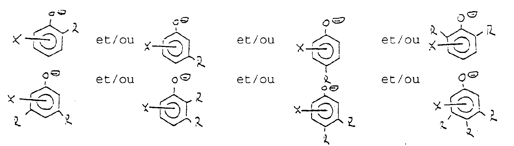 X désigne 0 à 4 atomes de chlore etR est un atome d'hydrogène et/ou un groupe hydroxyle et/ou un atome d'halogène et/ou un radical alkyle ou chloralkyle linéaire ou ramifié en C₁-C₆, et/ou un radical alcoxy ou chloralcoxy en C₁-C₆, dans une disposition linéaire ou ramifiée.
 - Système de catalyseurs selon la revendication 1, caractérisé en ce que le catalyseur se compose d'hydrogéno-métacrésolate-trichloroferrate, d'ortho-crésolate-trichloroferrate de sodium, de bis-para-crésolate-trichloraluminate de calcium ou de tris-ortho-crésolate-trichloraluminate de cérium.
- Système de catalyseurs selon la revendication 1, caractérisé en ce que la préparation du système de catalyseurs s'effectue par mélange des composés Z+mClm, Me+nCln et des composés phénoli.ques L dans des quantités équivalentes, l'équivalence entre Z+mClm et le composé phénolique L présentant un domaine de dispersion qui est à chaque fois de 0,9 à 1,1:1 parties équivalentes, et l'équivalence entre Me+nCln et le composé phénolique L un domaine de dispersion qui est à chaque fois de 0,5 à 1,5:1 partie équivalente.
- Système de catalyseurs selon les revendications 1 ou 3, caractérisé en ce que l'équivalence entre Me+nCln et le composé phénolique L présente un domaine de dispersion qui est à chaque fois de 0,9 à 1,1:1 partie équivalente.
- Système de catalyseurs selon les revendications 1, 2, 3 ou 4, caractérisé en ce que la préparation s'effectue par mélange d'acide chlorhydrique, de méta-crésol et de chlorures ferrique.
- Système de catalyseurs selon les revendications 1, 2, 3 ou 4, caractérisé en ce que la préparation s'effectue par mélange de chlorure de sodium, d'ortho-crésol et de chlorure ferrique.
- Système de catalyseurs selon les revendications 1, 2, 3 ou 4, caractérisé en ce que la préparation s'effectue par mélange de chlorure de calcium, de para-crésol et de chlorure d'aluminium.
- Procédé de préparation du 1,2-dichloréthane par réaction de l'éthylène avec le chlore, dans une zone réactionnelle qui contient un milieu réactionnel liquide circulant cycliquement, constitué d'hydrocarbures chlorés en C₂, à une température inférieure à la température de vaporisation du milieu, sous la pression régnant dans la zone réactionnelle, le cas échéant en présence d'oxygène comme inhibiteur pour éviter des réactions secondaires, en présence d'un système de catalyseurs selon les revendications précédentes, caractérisé en ce que :a) la concentration du système de catalyseur Me+n[Z+mClm.L]n, dissous ou en suspension dans le mélange réactionnel, calculée en Z+mClm, est de 0,01 à 1,0 % en poids par rapport à la quantité de mélange réactionnel et en ce que le système de catalyseur est envoyé dans le cycle, avec remplacement de l'éthylène et du chlore consommés,b) en éliminant de la zone réactionnelle dans une zone de faible pression, à des températures de réaction de 0 à 300 °C et sous des pressions s'opposant à une ébullition du milieu réactionnel dans l'espace réactionnel, avec utilisation partielle à totale de l'enthalpie de réaction libérée lors du chlorage de l'éthylène, pour la production de vapeur de 1,2-dichloréthane, du l,2-dichloréthane sous forme de vapeur, et en envoyant ces vapeurs au bas d'une colonne de rectification, etc) en condensant à des températures de réaction de 0 à 120 °C les vapeurs chaudes à la tête de colonne par refroidissement avec de l'eau ou de l'air, à des températures de réaction de 120 à 300 °C, en utilisant la chaleur de réaction de vapeurs chaudes par échange de chaleur des vapeurs chaudes de la colonne de rectification avec un milieu d'échange de chaleur, etd) en maintenant un rapport de reflux minimum, exprimé par le rapport ponédral du reflux au produit formé, dans le cas d'un mode de conduite à basse température, de 2:1 parties en poids et dans le cas d'un mode de conduite à haute température, de 1:1 partie en poids, en renvoyant les vapeurs chaudes condensées plus ou moins surfondues dans l'espace réactionnel dans le cas du mode de conduite à basse température, mais surrefroidies à un maximum de 5 °C, par rapport à la température d'ébullition ou de condensation dans le cas d'un mode de conduite à haute température, ete) en prélevant au bas de la colonne de rectification le 1,2-dichloréthane produit sous forme liquide.
- Procédé selon la revendication 8, caractérisé en ce que la température de réaction est de 40 à 80 °C, la pression dans l'espace réactionnel est comprise entre 1 et 5 bars absolus et les vapeurs chaudes en tête de la colonne de rectification sont condensées sous une pression de 0,2 à 0,9 bar absolu par échange de chaleur indirect avec l'eau ou l'air et en ce que le condensat des vapeurs chaudes renvoyées dans l'espace réactionnel présente par rapport à la température d'ébullition une température abaissée d'environ 5 à 50 °C.
- Procédé selon la revendication 8, caractérisé en ce que la température de réaction est de 140 à 170 °C, la pression dans l'espace réactionnel est comprise entre 5 et 10 bars absolus et les vapeurs chaudes en tête de la colonne de rectification sont condensées sous une pression de 4,5 à 8,3 bars absolus par échange de chaleur indirect avec de l'eau chaude, avec production de vapeur saturée sous une pression de 2,25 à 6,0 bars absolus.
- Procédé selon les revendications 8, 9 ou 10, caractérisé en ce que l'on fait circuler cycliquement comme milieu réactionnel du 1,2-dichloréthane avec une vitesse de 0,1 à 5 m/s.
- Procédé selon les revendications 8, 9, 10 ou 11, caractérisé en ce que le rapport molaire de l'éthylène au chlore est de 1:1 et 1,005:1 et en ce que la vitesse des gaz dans l'espace réactionnel est comprise entre 0,01 et 1 m/s par rapport au courant d'éthylène gazeux.
- Procédé selon les revendications 8, 9, 10, 11 ou 12, caractérisé en ce que le temps de séjour du mélange de réactifs est de 0,2 à 2 minutes, rapporté à l'espace de réaction, de mélange et de circulation vide dans les conditions normales (0 °C, 1013 mbars), et en ce que le temps de réaction des réactifs dans l'espace réactionnel est compris entre 1,5 et 60 secondes.
- Procédé selon les revendications 8, 9, 10, 11, 12 ou 13, caractérisé en ce que l'on utilise comme inhibiteur de l'oxygène ou de l'air à une concentration de 0,01 à 10 % en volume, calculée à chaque fois en oxygène et par rapport à la quantité de chlore gazeux.
Applications Claiming Priority (2)
| Application Number | Priority Date | Filing Date | Title |
|---|---|---|---|
| DE4012529 | 1990-04-19 | ||
| DE4012529A DE4012529A1 (de) | 1990-04-19 | 1990-04-19 | Katalysatorsystem und verfahren zur herstellung von 1,2-dichlorethan durch chlorierung von ethylen unter einsatz dieses katalysatorsystems |
Publications (2)
| Publication Number | Publication Date |
|---|---|
| EP0453944A1 EP0453944A1 (fr) | 1991-10-30 |
| EP0453944B1 true EP0453944B1 (fr) | 1994-03-16 |
Family
ID=6404686
Family Applications (1)
| Application Number | Title | Priority Date | Filing Date |
|---|---|---|---|
| EP91106153A Expired - Lifetime EP0453944B1 (fr) | 1990-04-19 | 1991-04-17 | Système catalytique et procédé de préparation du 1,2-dichloroethane par chloration de l'éthylène en présence de ce système catalytique |
Country Status (5)
| Country | Link |
|---|---|
| US (1) | US5177233A (fr) |
| EP (1) | EP0453944B1 (fr) |
| JP (1) | JPH0790172B2 (fr) |
| DE (2) | DE4012529A1 (fr) |
| NO (1) | NO179400C (fr) |
Families Citing this family (6)
| Publication number | Priority date | Publication date | Assignee | Title |
|---|---|---|---|---|
| DE4318609A1 (de) * | 1993-01-27 | 1994-07-28 | Hoechst Ag | Verfahren und Vorrichtung zur Herstellung von 1,2-Dichlorethan durch Direktchlorierung |
| IT1270944B (it) † | 1993-02-10 | 1997-05-26 | Pressindustria A G | Procedimento continuo e impianto di alogenazione di elastomeri. |
| WO1997033849A1 (fr) * | 1996-03-13 | 1997-09-18 | Caprolactam Joint-Stock Company | Procede de production de 1,2-dichloroethane |
| DE19904836C1 (de) * | 1999-02-06 | 2000-08-31 | Krupp Uhde Gmbh | Verfahren zur Herstellung von 1,2-Dichlorethan |
| BR0112516A (pt) * | 2000-07-17 | 2003-09-09 | Univation Tech Llc | Sistema catalisador e seu emprego em um processo de polimerização |
| DE102004029147B4 (de) * | 2004-06-17 | 2008-01-03 | Uhde Gmbh | Verfahren und Vorrichtung zur Herstellung von 1,2-Dichlorethan mittels Direktchlorierung |
Family Cites Families (7)
| Publication number | Priority date | Publication date | Assignee | Title |
|---|---|---|---|---|
| JPS5257105A (en) * | 1975-11-04 | 1977-05-11 | Kanegafuchi Chem Ind Co Ltd | Gas phase chlorination process for ethylene |
| US4410747A (en) * | 1979-06-29 | 1983-10-18 | Ryo-Nichi Company Ltd. | Process for producing 1,2-dichloroethane |
| DE3247988A1 (de) * | 1982-12-24 | 1984-06-28 | Hoechst Ag, 6230 Frankfurt | Verfahren zur herstellung von 1,2-dichlorethan |
| DE3347153A1 (de) * | 1983-12-27 | 1985-07-04 | Hoechst Ag, 6230 Frankfurt | Verfahren zur herstellung von 1,2-dichlorethan |
| CA1229596A (fr) * | 1984-07-11 | 1987-11-24 | Sydney K. Brownstein | Complexe de transfert de charge ternaire |
| US4851598A (en) * | 1987-12-28 | 1989-07-25 | Brandeis University | Method of preparing metallocene compounds |
| US5021599A (en) * | 1989-08-31 | 1991-06-04 | Serpentix Conveyor Corporation | Redox-responsive anion receptors |
-
1990
- 1990-04-19 DE DE4012529A patent/DE4012529A1/de not_active Withdrawn
-
1991
- 1991-04-17 EP EP91106153A patent/EP0453944B1/fr not_active Expired - Lifetime
- 1991-04-17 DE DE91106153T patent/DE59101178D1/de not_active Expired - Fee Related
- 1991-04-17 US US07/686,616 patent/US5177233A/en not_active Expired - Fee Related
- 1991-04-18 NO NO911543A patent/NO179400C/no not_active IP Right Cessation
- 1991-04-19 JP JP3115582A patent/JPH0790172B2/ja not_active Expired - Lifetime
Also Published As
| Publication number | Publication date |
|---|---|
| NO179400B (no) | 1996-06-24 |
| DE59101178D1 (de) | 1994-04-21 |
| US5177233A (en) | 1993-01-05 |
| EP0453944A1 (fr) | 1991-10-30 |
| JPH04227853A (ja) | 1992-08-17 |
| NO911543D0 (no) | 1991-04-18 |
| JPH0790172B2 (ja) | 1995-10-04 |
| NO179400C (no) | 1996-10-02 |
| DE4012529A1 (de) | 1991-10-24 |
| NO911543L (no) | 1991-10-21 |
Similar Documents
| Publication | Publication Date | Title |
|---|---|---|
| DE2516567C3 (de) | Verfahren zum Chlorieren von phenolischen Verbindungen | |
| DE3314788A1 (de) | Mehrstufenverfahren zur herstellung von hexamethylendiisocyanat-1,6 und/oder isomeren aliphatischen diisocyanaten mit 6 kohlenstoffatomen im alkylenrest | |
| DE2447551C3 (de) | Verfahren zur Herstellung von Methylchlorid | |
| US2005707A (en) | Production of organic fluorine compounds | |
| DE69515036T2 (de) | Verfahren zur herstellung von difluormethan | |
| DE69710148T2 (de) | Verfahren zum Herstellen von Diarylcarbonat | |
| EP0453944A1 (fr) | Système catalytique et procédé de préparation du 1,2-dichloroethane par chloration de l'éthylène en présence de ce système catalytique | |
| EP0080098B1 (fr) | Procédé pour la préparation de 1,2-dichloroéthane | |
| DE3340624C1 (de) | Verfahren zur Herstellung von 1,2-Dichlorethan aus Ethylen und Chlorgas | |
| EP0026349A1 (fr) | Procédé de préparation de 1.2-dichloroéthane | |
| DE1902843B2 (fr) | ||
| US2165813A (en) | Chlorinated diphenyl ethers and method of making same | |
| US4150243A (en) | Process for the dealkylation of tert.-alkyl substituted phenols | |
| EP0111203B1 (fr) | Procédé pour la préparation de 1,2-dichloroéthane | |
| EP0249870A2 (fr) | Procédé pour l'enlèvement de l'éther diméthylique du chlorure de méthyle | |
| EP0082342B1 (fr) | Composition catalytique et procédé de production de 1,2-dichloréthane | |
| EP0452909B1 (fr) | Procédé d'épuration d'1,2-dichloroéthane non-converti d'un procédé de pyrolyse d'1,2-dichloroéthane | |
| DE69729214T2 (de) | Verfahren zur herstellung von polyfluoralkylgruppen enthaltenden säurechloriden | |
| DE1768367B1 (de) | Verfahren zur Herstellung von 1,2-Dichloraethan | |
| DE1468239A1 (de) | Halogenierungsverfahren | |
| EP1265837A2 (fr) | Procede de fabrication de chlorures d'acide o-chloromethylbenzoique | |
| EP0538704A1 (fr) | Procédé pour la monobenzylation de phénols p-substitués | |
| US7002043B2 (en) | Process for producing 1,1,1-trifluoroacetone | |
| DE2536261A1 (de) | Verfahren zur kontinuierlichen herstellung von o- und p-chlortoluol | |
| DE3504218A1 (de) | Verfahren zur herstellung von 4-alkyl-4'-formylbiphenyl |
Legal Events
| Date | Code | Title | Description |
|---|---|---|---|
| PUAI | Public reference made under article 153(3) epc to a published international application that has entered the european phase |
Free format text: ORIGINAL CODE: 0009012 |
|
| 17P | Request for examination filed |
Effective date: 19910417 |
|
| AK | Designated contracting states |
Kind code of ref document: A1 Designated state(s): BE DE FR GB IT NL SE |
|
| RAP1 | Party data changed (applicant data changed or rights of an application transferred) |
Owner name: WACKER-CHEMIE GMBH |
|
| 17Q | First examination report despatched |
Effective date: 19930524 |
|
| GRAA | (expected) grant |
Free format text: ORIGINAL CODE: 0009210 |
|
| AK | Designated contracting states |
Kind code of ref document: B1 Designated state(s): BE DE FR GB IT NL SE |
|
| REF | Corresponds to: |
Ref document number: 59101178 Country of ref document: DE Date of ref document: 19940421 |
|
| ITF | It: translation for a ep patent filed | ||
| GBT | Gb: translation of ep patent filed (gb section 77(6)(a)/1977) |
Effective date: 19940415 |
|
| NLR4 | Nl: receipt of corrected translation in the netherlands language at the initiative of the proprietor of the patent | ||
| ET | Fr: translation filed | ||
| PLBE | No opposition filed within time limit |
Free format text: ORIGINAL CODE: 0009261 |
|
| STAA | Information on the status of an ep patent application or granted ep patent |
Free format text: STATUS: NO OPPOSITION FILED WITHIN TIME LIMIT |
|
| EAL | Se: european patent in force in sweden |
Ref document number: 91106153.9 |
|
| 26N | No opposition filed | ||
| PGFP | Annual fee paid to national office [announced via postgrant information from national office to epo] |
Ref country code: FR Payment date: 20000330 Year of fee payment: 10 |
|
| PGFP | Annual fee paid to national office [announced via postgrant information from national office to epo] |
Ref country code: SE Payment date: 20000331 Year of fee payment: 10 Ref country code: NL Payment date: 20000331 Year of fee payment: 10 Ref country code: DE Payment date: 20000331 Year of fee payment: 10 |
|
| PGFP | Annual fee paid to national office [announced via postgrant information from national office to epo] |
Ref country code: GB Payment date: 20000403 Year of fee payment: 10 |
|
| PGFP | Annual fee paid to national office [announced via postgrant information from national office to epo] |
Ref country code: BE Payment date: 20000421 Year of fee payment: 10 |
|
| PG25 | Lapsed in a contracting state [announced via postgrant information from national office to epo] |
Ref country code: GB Free format text: LAPSE BECAUSE OF NON-PAYMENT OF DUE FEES Effective date: 20010417 |
|
| PG25 | Lapsed in a contracting state [announced via postgrant information from national office to epo] |
Ref country code: SE Free format text: LAPSE BECAUSE OF NON-PAYMENT OF DUE FEES Effective date: 20010418 |
|
| PG25 | Lapsed in a contracting state [announced via postgrant information from national office to epo] |
Ref country code: FR Free format text: THE PATENT HAS BEEN ANNULLED BY A DECISION OF A NATIONAL AUTHORITY Effective date: 20010430 Ref country code: BE Free format text: LAPSE BECAUSE OF NON-PAYMENT OF DUE FEES Effective date: 20010430 |
|
| BERE | Be: lapsed |
Owner name: WACKER-CHEMIE G.M.B.H. Effective date: 20010430 |
|
| PG25 | Lapsed in a contracting state [announced via postgrant information from national office to epo] |
Ref country code: NL Free format text: LAPSE BECAUSE OF NON-PAYMENT OF DUE FEES Effective date: 20011101 |
|
| EUG | Se: european patent has lapsed |
Ref document number: 91106153.9 |
|
| GBPC | Gb: european patent ceased through non-payment of renewal fee |
Effective date: 20010417 |
|
| NLV4 | Nl: lapsed or anulled due to non-payment of the annual fee |
Effective date: 20011101 |
|
| PG25 | Lapsed in a contracting state [announced via postgrant information from national office to epo] |
Ref country code: DE Free format text: LAPSE BECAUSE OF NON-PAYMENT OF DUE FEES Effective date: 20020201 |
|
| REG | Reference to a national code |
Ref country code: FR Ref legal event code: ST |
|
| PG25 | Lapsed in a contracting state [announced via postgrant information from national office to epo] |
Ref country code: IT Free format text: LAPSE BECAUSE OF NON-PAYMENT OF DUE FEES;WARNING: LAPSES OF ITALIAN PATENTS WITH EFFECTIVE DATE BEFORE 2007 MAY HAVE OCCURRED AT ANY TIME BEFORE 2007. THE CORRECT EFFECTIVE DATE MAY BE DIFFERENT FROM THE ONE RECORDED. Effective date: 20050417 |