EP0453994B1 - Servolenkung mit integraler Parallelsteuerung - Google Patents
Servolenkung mit integraler Parallelsteuerung Download PDFInfo
- Publication number
- EP0453994B1 EP0453994B1 EP91106339A EP91106339A EP0453994B1 EP 0453994 B1 EP0453994 B1 EP 0453994B1 EP 91106339 A EP91106339 A EP 91106339A EP 91106339 A EP91106339 A EP 91106339A EP 0453994 B1 EP0453994 B1 EP 0453994B1
- Authority
- EP
- European Patent Office
- Prior art keywords
- fluid
- axial
- port
- passage
- follow
- Prior art date
- Legal status (The legal status is an assumption and is not a legal conclusion. Google has not performed a legal analysis and makes no representation as to the accuracy of the status listed.)
- Expired - Lifetime
Links
- 239000012530 fluid Substances 0.000 claims description 418
- 238000004891 communication Methods 0.000 claims description 128
- 230000007935 neutral effect Effects 0.000 claims description 58
- 230000033001 locomotion Effects 0.000 claims description 23
- 230000004044 response Effects 0.000 claims description 21
- 238000006073 displacement reaction Methods 0.000 claims description 4
- 230000000903 blocking effect Effects 0.000 claims description 2
- 230000000977 initiatory effect Effects 0.000 description 4
- 230000004075 alteration Effects 0.000 description 2
- 230000004323 axial length Effects 0.000 description 2
- 210000004907 gland Anatomy 0.000 description 2
- 230000002452 interceptive effect Effects 0.000 description 2
- 230000004048 modification Effects 0.000 description 2
- 238000012986 modification Methods 0.000 description 2
- 240000008042 Zea mays Species 0.000 description 1
- 235000005824 Zea mays ssp. parviglumis Nutrition 0.000 description 1
- 235000002017 Zea mays subsp mays Nutrition 0.000 description 1
- 230000001133 acceleration Effects 0.000 description 1
- 230000009471 action Effects 0.000 description 1
- 230000003466 anti-cipated effect Effects 0.000 description 1
- 230000008859 change Effects 0.000 description 1
- 238000010276 construction Methods 0.000 description 1
- 230000001276 controlling effect Effects 0.000 description 1
- 235000005822 corn Nutrition 0.000 description 1
- 230000001186 cumulative effect Effects 0.000 description 1
- 230000018109 developmental process Effects 0.000 description 1
- 230000000694 effects Effects 0.000 description 1
- 238000003306 harvesting Methods 0.000 description 1
- 230000003993 interaction Effects 0.000 description 1
- 238000009428 plumbing Methods 0.000 description 1
- 230000001105 regulatory effect Effects 0.000 description 1
- 238000007789 sealing Methods 0.000 description 1
Images



Classifications
-
- B—PERFORMING OPERATIONS; TRANSPORTING
- B62—LAND VEHICLES FOR TRAVELLING OTHERWISE THAN ON RAILS
- B62D—MOTOR VEHICLES; TRAILERS
- B62D5/00—Power-assisted or power-driven steering
- B62D5/06—Power-assisted or power-driven steering fluid, i.e. using a pressurised fluid for most or all the force required for steering a vehicle
- B62D5/09—Power-assisted or power-driven steering fluid, i.e. using a pressurised fluid for most or all the force required for steering a vehicle characterised by means for actuating valves
- B62D5/093—Telemotor driven by steering wheel movement
- B62D5/097—Telemotor driven by steering wheel movement gerotor type
-
- B—PERFORMING OPERATIONS; TRANSPORTING
- B62—LAND VEHICLES FOR TRAVELLING OTHERWISE THAN ON RAILS
- B62D—MOTOR VEHICLES; TRAILERS
- B62D6/00—Arrangements for automatically controlling steering depending on driving conditions sensed and responded to, e.g. control circuits
-
- Y—GENERAL TAGGING OF NEW TECHNOLOGICAL DEVELOPMENTS; GENERAL TAGGING OF CROSS-SECTIONAL TECHNOLOGIES SPANNING OVER SEVERAL SECTIONS OF THE IPC; TECHNICAL SUBJECTS COVERED BY FORMER USPC CROSS-REFERENCE ART COLLECTIONS [XRACs] AND DIGESTS
- Y10—TECHNICAL SUBJECTS COVERED BY FORMER USPC
- Y10T—TECHNICAL SUBJECTS COVERED BY FORMER US CLASSIFICATION
- Y10T137/00—Fluid handling
- Y10T137/8593—Systems
- Y10T137/86493—Multi-way valve unit
- Y10T137/86574—Supply and exhaust
- Y10T137/86638—Rotary valve
- Y10T137/86646—Plug type
- Y10T137/86662—Axial and radial flow
-
- Y—GENERAL TAGGING OF NEW TECHNOLOGICAL DEVELOPMENTS; GENERAL TAGGING OF CROSS-SECTIONAL TECHNOLOGIES SPANNING OVER SEVERAL SECTIONS OF THE IPC; TECHNICAL SUBJECTS COVERED BY FORMER USPC CROSS-REFERENCE ART COLLECTIONS [XRACs] AND DIGESTS
- Y10—TECHNICAL SUBJECTS COVERED BY FORMER USPC
- Y10T—TECHNICAL SUBJECTS COVERED BY FORMER US CLASSIFICATION
- Y10T137/00—Fluid handling
- Y10T137/8593—Systems
- Y10T137/87169—Supply and exhaust
Definitions
- the present invention relates to fluid controllers of the type used to control the flow of fluid from a source of pressurized fluid to a fluid pressure actuated device such as a steering cylinder which comprises part of a full-fluid-linked vehicle steering system.
- a fluid controller as defined in the preamble of claim 1 is known from EP-A-0 171 247.
- the cooperating valve members define orifices the area of which available for the flow of hydraulic fluid within the controller is changed by the relative axial movement of the valve members to thereby alter the degree of power steering assistance, wherein this relative axial movement is a function of the vehicle speed or various signals other than, or in combination with, vehicle speed, for example vehicle lateral acceleration or angular turn of the steering wheel.
- a typical fluid controller of the type to which the present invention relates includes a housing which defines various fluid ports, and further includes a fluid meter, a valve means, and an arrangement for imparting follow-up movement to the valve means, in response to the flow of fluid through the fluid meter.
- the flow through the controller valve means is directly proportional to the area of the variable flow control orifices in the main fluid path, the area of the flow control orifices in turn being proportional to the rate at which the steering wheel is rotated.
- a typical example of a vehicle which utilizes a fluid controller of this type would be an agricultural tractor or combine.
- a fluid controller of this type would be an agricultural tractor or combine.
- the crop e.g., rows of corn
- the position of the steering cylinder accordingly so that the vehicle follows the crop rows.
- an improved fluid controller operable to control the flow of fluid from a source of pressurized fluid to a fluid pressure operated device;
- the controller being of the type including housing means defining an inlet port for connection to the source of pressurized fluid, a return port for connection to a reservoir, and, first and second control fluid ports for connection to the fluid pressure operator device; valve means disposed in the housing means and comprising a primary, rotatable valve member and a cooperating, relatively rotatable follow-up valve member, said primary and follow-up valve members defining a neutral rotary position and a first rotary operating position in which said primary valve member is rotatably displaced from said neutral position, relative to said follow-up valve member; said housing means and said primary and follow-up valve members cooperating to define a first main fluid path providing fluid communication from said inlet port to said first control fluid port and from said second control fluid port to said return port when said valve members are in said first rotary operating position; said primary and follow-up valve members
- the controller further includes fluid actuated means for imparting follow-up movement to said follow-up valve member proportional to the volume of fluid flow through said fluid actuated means; said first main fluid path including said fluid actuated means and said first parallel path excluding said fluid actuated means.
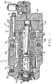
- Fig. 1 is an axial cross-section of a fluid controller made in accordance with the present invention.
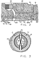
- FIG. 2 is an enlarged, axial cross-section, similar to FIG. 1, but on a different plane, and showing the sleeve valve axially displaced from its neutral axial position.
- FIG. 3 is an enlarged, transverse cross-section, taken on line 3-3 of FIG. 1, showing the springs which bias the spool and sleeve toward their neutral rotary position.
- FIG. 4 is an enlarged, axial layout view, taken on line 4-4 of FIG. 1.
- FIG. 5 is an enlarged, fragmentary, axial cross-section like FIG. 1, but taken on a different plane, illustrating the forward spring chamber.
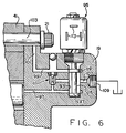
- FIG. 6 is an enlarged, axial cross-section, like FIG. 1, of the electrohydraulic valve portion of the controller, but in an actuated position.
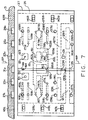
- FIG. 7 is an overlay view of the valving used in the fluid controller of FIG. 1, but on a larger scale than in FIG. 1, and with the valving in both the neutral rotary and neutral axial position.
- FIG. 8 is an overlay view, similar to FIG. 7, illustrating the rotary actuated position of the valving.
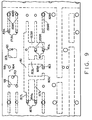
- FIG. 9 is a fragmentary overlay view, similar to FIG. 7, but further enlarged relative to FIG. 7, illustrating the valving in the axial actuated position.
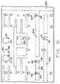
- FIG. 10 is an overlay view, similar to FIG. 9, and on the same scale, illustrating the valving in an axial actuated position, being overridden by rotary input to steer in the opposition direction.
- FIG. 11 is a fragmentary overlay view, similar to FIG. 9, but with the valving in the opposite axial actuated position from that shown in FIG. 9.
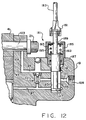
- FIG. 12 is an axial cross-section, similar to FIG. 6, but further enlarged relative to FIG. 6, illustrating an alternative embodiment in which the axial position of the sleeve valve is controlled by a hydromechanical valve.
- FIG. 1 illustrates a fluid controller, generally designated 11, made in accordance with the teachings of the present invention.
- the fluid controller 11 may be of the general type illustrated and described in U.S. Patent No. RE 25,126, and in the subject embodiment, is more specifically of the type illustrated and described in U.S. Patent No. 4,033,377, both of which are assigned to the assignee of the present invention and incorporated herein by reference.
- the fluid controller 11 comprises several sections, including a valve housing 13, a port plate 15, a section comprising a fluid meter 17, and an end cap 19. These sections are held together in tight sealing engagement by means of a plurality of bolts 21, which are in threaded engagement with the valve housing 13.
- the valve housing 13 defines a fluid inlet port 23 (shown in solid lines only in FIG. 2), a fluid return port 25, and a pair of control (cylinder) fluid ports 27 and 29.
- the valve housing 13 also defines a load signal port 31.
- the inlet port 23 would be connected in fluid communication with a source of pressurized fluid such as a hydraulic pump (not shown) while the return port 25 would be in fluid communication with a system reservoir (shown only in FIG. 6).
- the control ports 27 and 29 would be connected to the opposite ends of a steering cylinder (not shown), while the load signal port 31 would be connected to a fluid pressure responsive device for varying the delivery of fluid to the controller 11, in the manner illustrated and described in U.S. Patent No. 4,620,416, also assigned to the assignee of the present invention, and incorporated herein by reference.
- the valve housing 13 defines a valve bore 33, and rotatably disposed therein is a valving arrangement, comprising a primary, rotatable valve member 35 (referred to hereinafter as the "spool"), and a cooperating, relatively rotatable follow-up valve member 37 (referred to hereinafter as the "sleeve").
- a valving arrangement comprising a primary, rotatable valve member 35 (referred to hereinafter as the "spool"), and a cooperating, relatively rotatable follow-up valve member 37 (referred to hereinafter as the "sleeve").
- a portion having a reduced diameter and defining a set of internal splines 39 which provide for a direct mechanical connection between the spool 35 and a steering wheel (not shown).
- the spool 35 and sleeve 37 will be described in greater detail subsequently.
- the fluid meter 17 may be of the type well-known in the art, and in the subject embodiment, includes an internally-toothed ring member 41, and an externally-toothed star member 43, which is eccentrically disposed within the ring 41, for orbital and rotational movement relative thereto.
- the star 43 defines a set of internal spines 45, and in splined engagement therewith is a set of external splines 47 formed at the rearward end of a drive shaft 49.
- the drive shaft 49 has a bifurcated forward end 51 permitting driving connection between the shaft 49 and the sleeve 37, by means of a drive pin 53.
- the ends of the pin 53 pass through a pair of oversized pin openings 55 defined by the spool 35, and are received in relatively close fitting openings in the sleeve 37.
- the configuration of the pin openings 55 will be described in greater detail in connection with the spool-sleeve layouts of Figs. 7 through 11.
- pressurized fluid flowing from the inlet port 23 through the various passages defined by the spool 35 and sleeve 37 then flows through the fluid meter 17, causing orbital and rotational movement of the star 43 within the ring 41.
- Such movement of the star 43 causes rotational follow-up movement of the sleeve 37, by means of the drive shaft 49 and drive pin 53, to maintain a particular relative rotational displacement (referred to hereinafter as a "rotary operating position") between the spool 35 and sleeve 37, proportional to the rate of rotation of the steering wheel.
- a plurality of leaf springs 57 extend through openings in the spool 35, biasing the sleeve 37 toward the rotary neutral position (as that term will be defined in connection with FIG. 7), relative to the sleeve 35.
- valve bore 33 of the valve housing 13 defines a plurality of annular fluid chambers surrounding the sleeve 37, to provide fluid communication between the various ports and the outer surface of the sleeve 37.
- An annular chamber 23c receives pressurized fluid from the inlet port 23, while a pair of annular chambers 25c, which are interconnected by a fluid passage 25p, communicate return fluid to the return port 25.
- an annular chamber 27c provides communication to or from the control port 27, while an annular chamber 29c provides communication to or from the control port 29.
- an annular chamber 31c provides communication with the load signal port 31, by means of a fluid passage 31p.
- the toothed interaction of the star 43, orbiting and rotating within the ring 41, defines a plurality of expanding and contracting fluid volume chambers 59, and adjacent each such chamber 59, the port plate 15 defines a fluid port 61.
- the valve housing 13 defines a plurality of axial bores 63 (only one of which is shown in FIG. 1), each of which is in open communication with one of the fluid ports 61.
- the valve housing 13 further defines a pair of radial bores 65L and 65R, providing communication between each of the axial bores 63 and the valve bore 33, as will be described in greater detail subsequently.
- Fluid flowing from the contracting fluid volume chambers 59 of the meter 17 flows through other of the axial bores 63, then into the radial bores 65L, then through another variable orifice in the valving, and out to the cylinder port 27. Fluid returning from the steering cylinder enters the cylinder port 29, then flows through another series variable orifice in the valving, and then out to the return port 25.
- the above-described fluid path is typically referred to as the "main fluid path", and the use of that term hereinafter will be understood to mean the above-described fluid path when the spool and sleeve are in a rotary operating position.
- such relative axial motion is accomplished by making the sleeve 37 axially shorter than the adjacent portion of the spool 35, and providing means for axially displacing the sleeve 37, relative to the spool 35, from a neutral axial position to an axial operating position.
- a seal gland bushing 67 disposed radially between the housing 13 and the reduced diameter portion of the spool 35 which cooperates with the housing 13, the spool 35, and the sleeve 37 to define a forward pressure chamber 69.
- the chamber 69 receives pressurized fluid through an angled passage 71 (see FIG. 5) defined by the spool 35, from an interior chamber 73 defined primarily by the spool 35. The manner of controlling the fluid pressure in the chamber 73 and therefore in the chamber 69 will be described subsequently.
- the interior chamber 73 in the present invention is isolated from the return port 25, such that there may be another fluid pressure actuated device connected downstream of the controller, resulting in a high back pressure in the return port 25.
- the sleeve 37 defines a pair (only one of which is shown in FIG. 4) of diametrically disposed, generally U-shaped openings 75 in which the outer ends of the springs 57 are seated.
- an annular washer 77 Disposed adjacent the seal gland bushing 67 is an annular washer 77, and disposed on the other side of the chamber 69 is an annular washer 79.
- a wave spring 81 Seated between the washers 77 and 79 is a wave spring 81 which comprises an axial centering spring, operable to bias the sleeve 37 toward its neutral axial position shown in FIG. 1.
- the axial position of the sleeve 37 as shown in FIG. 5 is not the neutral axial position, but is a position resulting from the forward chamber 69 being pressurized, and corresponds generally to the axial operating position illustrated in FIG. 9, which will be described subsequently.
- the housing 13, the port plate 15, the spool 35, and the sleeve 37 cooperate to define a rearward pressure chamber 83 which, when pressurized, biases the sleeve 37 to the position shown in FIG. 2, corresponding generally to the axial operating position illustrated in FIG. 11, which will be described subsequently.
- An annular washer 85 is seated against a shoulder defined by the housing 13, and seated between the washer 85 and the port plate 15 is a wave spring 87 which comprises an axial centering spring, and is preferably of the same size, construction, and spring rate as the wave spring 81 shown in FIG. 4. It should be understood by those skilled in the art that with the sleeve 37 biased to the position shown in FIG.
- the wave spring 87 is compressed and is biasing the sleeve toward its neutral axial position in opposition to the biasing force of the fluid pressure in the chamber 69, whereas, when the sleeve is in the position shown in FIG. 2, the wave spring 81 is being compressed and is biasing the sleeve toward its neutral axial position in opposition to the biasing force of the fluid pressure in the chamber 83.
- the inlet port 23 communicates with the annular chamber 23c by means of a fluid passage 23p.
- the rearward chamber 83 includes a radially outward chamber portion 89 which is in fluid communication with the inlet port 23 by means of the passage 23p and a restricted axial passage 91.
- the end cap 19 defines a stepped bore 93, adapted to receive an electromagnetic solenoid valve, generally designated 95.
- the end cap 19 defines three different axial fluid passages, each of which intersects the stepped bore 93.
- An axial passage 97 intersects the lower end of the bore 93, and is in open fluid communication with the interior chamber 73, defined primarily by the spool 35, but also defined partly by the star 43.
- An axial passage 99 intersects the upper end of the stepped bore 93, and also includes a radial passage portion 101 which is in open communication with a reduced diameter shank portion 103 of one of the bolts 21.
- the rearward pressure chamber 83 includes a radially outward chamber portion 105 which is in open communication with the space surrounding the shank portion 103.
- an axial passage 107 Disposed between the axial passages 99 and 97 is an axial passage 107 which intersects the bore 93 and terminates at a port 109 which is illustrated in FIG. 6 as being in communication with the system reservoir.
- the port 109 could be connected to some other source of relatively low pressure fluid, or could even be connected to a source of relatively higher pressure fluid, thus eliminating the need to tap pressurized pilot fluid from the inlet port 23, as shown in FIG. 2.
- the left end (in FIG. 6) of the axial passage 107 is in communication with a relief valve assembly 111, the function of which is to relieve any excess pressure from either of the axial passages 97 or 99 to the passage 107, then to the port 109.
- the passages 91 and 121 would both be connected, through a restriction, to passage 25p, and the fluid return port would be connected to a source of low pressure, such as the system reservoir.
- the relief valve assembly 111 would be vented by passage 107, not to the port 109, but instead, to a low pressure source.
- Excess is meant any pressure greater than that needed or desired in the chambers 69 and 83, to actuate the sleeve 37.
- the pilot pressure in the interior chamber 73 is more than about 100 or 200 psi., the result will be an excessive force biasing the spool 35 forwardly (to the left in FIG. 5), which may cause binding of the spool against the washer 77, interfering with proper steering action.
- the solenoid valve 95 includes a set of electrical contacts 113, adapted to receive an external electrical signal (to be referred to hereinafter as signal 113) from a control source, such as a microprocessor.
- the solenoid valve 95 further includes a valve member, generally designated 115, including a pair of spool lands 117 and 119, and being movable from a neutral, centered position (FIG. 1) to either an upward actuated position (not shown), or a downward actuated position (FIG. 6).
- the solenoid valve 95 could be of the ON-OFF type, and pulse-width-modulated between the centered position and the desired actuated position, or could be proportional between the two extreme actuated positions.
- Various other electrohydraulic control arrangements could be utilized, all of which are within the scope of the invention, as long as they perform the function set forth in the appended claims.
- pressurized pilot fluid is communicated from the inlet port 23 into the interior chamber 73 by means of a pilot passage 121 defined by the sleeve 37, and an enlarged pilot opening 123, defined by the spool 35.
- the pilot passage 121 is approximately centered relative to the pilot opening 123 (see FIG. 7), as is the drive pin 53 within the pin openings 55.
- the pilot passage 121 is shifted over to one side of the pilot opening 123, but as is shown in Figs. 2 and 11, it is still in a position to permit communication from the inlet port 23 to the interior chamber 73.
- the spool land 117 With the solenoid valve 95 in a neutral or unactuated condition, as shown in FIG. 1, the spool land 117 permits fluid communication from the axial passage 97 to the port 109, while the spool land 119 permits fluid communication from the axial passage 99 to the port 109. In this condition, there is no substantial buildup of pilot pressure in the interior chamber 73 and forward pressure chamber 69, or in the rearward pressure chamber 83. As a result, the biasing force of the axial centering springs 81 and 87 is sufficient to bias the sleeve 37 to its neutral axial position as shown in Figs. 1 and 7.
- the valve member 115 is shifted downward to the position shown in FIG. 6 in which the spool land 117 permits unrestricted communication between the axial passage 97 and the port 109.
- the spool land 119 is now in a position blocking communication from the axial passage 99 to the port 109, resulting in a buildup of pressure in the radial passage portion 101, the region surrounding the shank portion 103, the chamber portion 105, and the rearward pressure chamber 83.
- the buildup of pressure in the chamber 83 is a result of pressure being communicated from the inlet port 23 through the passage 91 and chamber portion 89 into the rearward chamber 83.
- the sleeve 37 is biased to the left, to the position shown in Figs. 2 and 11, in opposition to the biasing force of the spring 81 in the forward chamber 69.
- the valve member 115 is moved upward from its neutral position, such that the spool land 117 blocks communication from the passage 97 to the port 109, pilot pressure would build in the interior chamber 73 and forward chamber 69, fed by pilot flow through the pilot passage 121 and pilot opening 123, thus shifting the sleeve 37 to the right, to the position shown in Figs. 5 and 9, in opposition to the biasing force of the spring 87 in the rearward chamber 83.
- pilot pressure arrangement and electrohydraulic controls illustrated and described herein are merely one example, and that various other pilot arrangements could be utilized.
- the pilot flow to the forward chamber 69 could be through the housing 13, while the communication between the rearward chamber 83 and the solenoid valve 95 could be through the spool 35 and the interior chamber 73.
- the solenoid valve 95 could be located in the housing 13, which would result in a substantially different arrangement of the various pilot passages.
- pilot pressure is taken from the inlet port 23 in the subject embodiment
- pilot pressure could also be taken from a "regulated" return port 25, i.e., a return port which is maintained at a predetermined pressure, such as 100 psi.
- a predetermined pressure such as 100 psi.
- all that is essential is that there be some means included which is operable to bias the spool and sleeve toward their neutral axial position, and that there be some means included which is operable to displace the spool and sleeve to one or more axial operating positions.
- the invention provides the ability to actuate the valve members axially relative to each other, in addition to the normal rotary actuation. It is another important aspect of the present invention that the valve members be laid out such that axial actuation thereof results in a flow path being defined within the controller which is preferably separate and distinct from the main fluid path, normally defined in response to relative rotation of the valve members.
- the resulting fluid path should be a path which is in parallel with the main fluid path, i.e., it also communicates from the inlet port 23 to one of the control ports 27 or 29, and then from the other of the control ports 27 or 29 to the return port 25, but with the parallel path being structurally separate and distinct from the main path, although still defined within the spool 35 and sleeve 37.
- the main (rotary) fluid path and the parallel (axial) fluid path be arranged such that either one may be actuated by itself, and operation of the parallel (axial) fluid path may be overridden by a rotary input to the controller.
- the main fluid path typically includes the fluid meter 17, whereas it is a still further aspect of the present invention that the parallel fluid path exclude the fluid meter, as will be described in greater detail in connection with FIG. 9.
- axial In connection with the subsequent description of the valving arrangement, and in the appended claims, many elements (such as ports, passages, and chambers) are referred to by means of the term “axial". It will be understood by those skilled in the art that such use of the term “axial” is not necessarily intended to denote a structural feature of the particular element, or a particular orientation, but instead, is intended to indicate that that particular element is related to the axial actuation of the sleeve 37, or is involved in defining the parallel (axial) fluid path.
- the spool 35 and sleeve 37 will be described in greater detail, with regard to the various ports and passages defined by the spool and sleeve.
- many of the ports and passages are arranged symmetrically, or generally symmetrically with respect to an imaginary central reference plane RP passing just to the left of the chamber 23c, and such elements will be described by a reference numeral followed by either an R or an L to indicate that the element is located on either the right side or the left side, respectively, of the central reference plane RP.
- certain of the elements do not have a corresponding element oppositively disposed about the reference plane RP, and will be referred to by use of a reference numeral alone.
- FIGS. 7 through 11 are intended to illustrate primarily the interface between the spool 35 (dashed lines) and the sleeve 37 (solid lines), and as a result, certain structural features which appear only on the outer surface of the sleeve 37 will be shown only in FIG. 7, but will not be repeated in the subsequent spool-sleeve overlay views.
- the spool 35 and sleeve 37 may appear to have the same axial length, but that is done only for ease of illustration, and it should be apparent from reviewing FIGS. 1, 2 and 5 that the sleeve 37 is necessarily somewhat shorter in the axial direction than is the spool 35.
- the spool 35 defines a pair of annular meter grooves 125L and 125R, which are axially aligned with the radial bores 65L and 65R, respectively.
- a pressure passage 127L In communication with the meter groove 125L is a pressure passage 127L, and in communication with the meter groove 125R is a pressure passage 127R.
- Adjacent the end of the pressure passage 127L is a return passage 129R, and adjacent the end of the pressure passage 127R is a return passage 129L.
- the sleeve 37 defines a pressure port 131, disposed generally adjacent the imaginary reference plane RP. Disposed to the of left the port 131 is a pair of load sensing ports 133L and 133R, both of which are in open communication with an annular load sensing groove 135, defined on the outer surface of the sleeve 37.
- the groove 135 is in continuous communication with the load signal port 31 by means of the annular chamber 31c and the passage 31p.
- the sleeve 37 further defines an operating port 137L disposed adjacent the pressure passage 127L, and an operating port 137R, disposed adjacent the pressure passage 127R.
- the sleeve 37 also defines an operating port 139L disposed adjacent the return passage 129L, and an operating port 139R disposed adjacent the return passage 129R. Also disposed adjacent the return passage 129L is a return port 141L, and also disposed adjacent the return passage 129R is a return port 141R. Finally, the sleeve 37 defines a plurality of meter ports 143L in continuous communication with the meter groove 125L, and a plurality of meter ports 143R, in continuous communication with the meter groove 125R. Each of the meter ports 143L and 143R includes a generally rectangular opening 145L or 145R, respectively, defined by the outer surface of the sleeve 37.
- the purpose of the openings 145L and 145R is to permit commutating fluid communication between the meter ports 143L and the radial bores 65L, and between the meter ports 143R and the radial bores 65R, even when the sleeve 37 has been axially displaced in either direction from the neutral axial position shown in FIG. 7.
- the pressure in the passage 127R (downstream of the A1r orifice) is being "sensed” or communicated through the load sensing port 133R to the load signal port 31 as described previously. Fluid flowing through the A1r orifice then flows into the meter groove 125R, then through the meter ports 143R to the meter 17, returning from the meter 17 and through the meter ports 143L and into the meter groove 125L. This metered fluid then enters the pressure passage 127L which is now overlapped by the operating port 137L to define a variable flow control orifice (A4r). Metered fluid flows from the A4r orifice into the annular chamber 27c, and from there to the control port 27 and into the steering cylinder.
- A4r variable flow control orifice
- Fluid returning from the exhaust side of the steering cylinder flows to the control port 29, then into the annular chamber 29c and into an A5r orifice defined by the overlap of the operating port 139R and the return passage 129R.
- This return fluid then flows through an A6r orifice defined by the overlap between the return passage 129R and the return port 141R.
- Flow through the A6r orifice then enters the annular chamber 25c (the one on the right side of the central reference plane RP), then flows to the return port 25 and to the system reservoir.
- the above-described flow path comprises the main fluid path defined when the spool and sleeve are displaced from the neutral rotary position to a rotary operating position.
- the spool and sleeve are still in a neutral axial position relative to each other. Note in FIG. 8 the shifted position of the pin 53 within the opening 55, and also the shifted position of the pilot passage 121 within the opening 123.
- the spool 35 defines a main, axially oriented passage 151, and in communication therewith, a pair of circumferentially oriented passages 153L and 153R.
- the passage 153L feeds a pair of pressure passages 155L
- the passage 153R feeds a pair of pressure passages 155R.
- spool 35 In communication with the main passage 151 is a pair of axially oriented passages 157L, and a pair of axially oriented passages 157R.
- the spool 35 defines three return passages 159L, and three return passages 159R.
- the sleeve 37 defines a pair of pressure ports 161 which are in continuous fluid communication with the inlet port 23 through the annular chamber 23c, and a third pressure port 161 in continuous communication with the axially oriented passage 151.
- the overlay view of FIG. 7 comprises approximately 180 o of the spool and sleeve, such that the arrangement shown in FIG. 7 is duplicated diametrically opposite, and the continuous communication of one port 161 with the passage 151 provides radial pressure balancing of the spool 35 relative to the sleeve 37.
- the pressure ports 161 are preferably evenly spaced between the pressure passages 155L and 155R.
- the sleeve 37 defines a load sensing port 163 which, in the neutral axial position, is evenly disposed between a pair of load sensing passages 165L and 165R.
- the spool and sleeve are in the neutral rotary and neutral axial position, it is necessary to drain the load sensing signal from the load sensing circuit, including the groove 135.
- the spool is provided with a drilled hole 164 communicating with the interior chamber 73, and the sleeve is provided with a drilled hole 166 which communicates between the groove 135 and the hole 164.
- the load sensing circuit is drained to the interior chamber 73, but as the spool and sleeve are displaced in either the rotary or axial position, communication between the holes 164 and 166 is discontinued, and load pressure begins to build in the groove 135, in the normal manner.
- sleeve 37 defines a return port 171L disposed adjacent the end of each of the return passages 159L when the valve members are in the neutral axial position of FIG. 7, and at the same time, defines a return port 171R adjacent the end of each of the return passages 159R.
- the load sensing port 163 is now in communication with the load sensing passage 165R, such that the fluid pressure downstream of the A1a orifice is sensed and communicated back to the load signal port 31.
- flow through the A1a orifice flows through the passages 157L which are now in communication with the operating ports 167L, to define a variable flow control orifice A4a.
- the A4a "orifice" really comprises the cumulative orifice area defined by both of the operating ports 167L overlapping both of the passages 157L.
- Fluid returning from the steering cylinder through the annular chamber 29c flows through the operating ports 169R into the return passages 159R, each of which is now in communication with a return port 171R, the overlap therebetween defining a variable flow control orifice A5a. Return fluid then flows through the A5a orifice to the annular chamber 25c and to the return port 25.
- the above-described flow path comprises the parallel fluid path which results when the spool and sleeve are in an axial operating position. It should be noted in connection with the above description of the parallel fluid path that, unlike the main fluid path, the parallel fluid path does not flow through the fluid meter 17. Therefore, the fluid flowing through the parallel fluid path is not “metered", whereas the fluid flowing through the main fluid path described in connection with FIG.
- controller of the present invention would be used in conjunction with an external closed-loop control system in which the axial actuation and parallel fluid path would be maintained only until an "error" signal would be reduced to zero, thus indicating no further need for parallel fluid flow, and returning the valve members to their neutral axial position.
- the axial actuation of the valve members will typically occur in response to the external electrical signal 113, and typically as part of an automatic guidance system on some sort of vehicle on which an operator is still present. It is one important aspect of the present invention for the operator to be able to manually override such an automatic guidance system in the event that, for example, the operator suddenly becomes aware of the need to deviate from the nominal vehicle path determined by the automatic guidance system. Therefore, referring now to FIG. 10, there is illustrated the relative position of the spool 35 and sleeve 37 after the operator has manually overridden the axial operating position shown in FIG. 9, in which the vehicle was in a right turn. In FIG. 9, the spool and sleeve are in the neutral rotary position, and all flow is through the parallel (axial) fluid path.
- pressurized fluid from the inlet port 23 now flows through the pressure port 131 into the pressure passage 127L to define a variable flow control orifice A1r, then into the meter groove 125L (not shown in FIG. 10), and then through the fluid meter 17.
- the metered fluid then flows into the meter groove 125R, then through the pressure passage 127R, which is now in fluid communication with the operating port 137R to define a variable flow control orifice A4r.
- the flow of metered fluid through the A4r orifice then flows to the annular chamber 29c, then to the control port 29, then to the steering cylinder, initiating a left turn.
- Fluid returning from the other end of the steering cylinder flows to the control port 27, then through the annular chamber 27c to the operating port 139L, which is now in fluid communication with the return passage 129L, to define a variable flow control orifice A5r.
- Flow through the A5r orifice then flows along the passage 129L and then through a variable flow control orifice A6r defined by the overlap of the return port 141L and the return passage 129L.
- Return flow through the A6r orifice then flows to the return port 25c in the manner described previously.
- FIG. 11 there is illustrated axial actuation of the sleeve 37, but in a direction opposite that shown in FIG. 9.
- the sleeve 37 was moved to the position shown in FIG. 5, initiating a right turn of the vehicle.
- the sleeve has been moved to the position shown in FIG. 2, initiating a left turn of the vehicle.
- the pressure ports 161 are now in communication with the respective pressure passages 155L, to define therebetween an A1a orifice.
- Pressurized fluid flows into the main passage 151, then flows to the right in FIG. 11 through the passages 157R which are now in communication with the operating ports 167R, to define a variable flow control orifice A4a.
- the load sensing port 163 is now in communication with the load sensing passage 165L, such that fluid pressure downstream of the A1a orifice is communicated to the load signal port 31.
- Fluid returning from the steering cylinder through the annular chamber 27c flows into the operating ports 169L then into the return passages 159L, each of which is now in communication with a return port 171L, the overlap therebetween defining a variable flow control orifice A5a.
- Return fluid then flows through the A5a orifice to the annular chamber 25c (the one on the left side of the imaginary reference plane RP in FIG. 11) and then to the return port 25.
- an important aspect of the present invention is the layout of the various ports and passages defined by the sleeve and spool which facilitate axial actuation of the valve members, to define a parallel fluid path, wherein the parallel fluid path excludes the fluid meter 17. More specifically, the present invention provides a controller in which the meter ports 143L and 143R are disposed adjacent the left and right axial ends of the spool and sleeve, respectively, it being recognized that the meter ports 143L and 143R are involved only in the definition of the main (rotary) fluid path.
- the various ports and passages defined by the sleeve and spool are arranged in a generally symmetrical pattern relative to the imaginary central reference plane RP.
- the general concept of such symmetry in the ports and passages of a controller was first described and illustrated in above-incorporated U.S. Patent No. 4,033,377, and in general, the benefits to be derived from the symmetrical arrangement shown herein are the same as the benefits described in 4,033,377.
- spool and sleeve of the present invention have been illustrated and described in connection with a load sensing embodiment.
- a load sensing embodiment As will be readily understood by one skilled in the art, if it is desired to apply the invention in a steering system requiring a closed center controller, no overall change of architecture of the spool and sleeve would be needed. Instead, it would be necessary merely to eliminate the load sensing port 31, as well as the passage 31p and the annular chamber 31c from the housing 13.
- the load sensing groove 135 and the load sensing ports 133L, 133R, and 163 would be eliminated from the sleeve 37, and the load sensing passages 165L and 165R would be eliminated from the spool 35.
- FIG. 12 there is illustrated an alternative embodiment of the present invention in which the electrohydraulic controls of FIG. 6 are replaced by a hydromechanical control, generally designated 181.
- a hydromechanical control generally designated 181.
- those elements which are the same or substantially the same as in FIG. 6 bear the same reference numeral, and new elements bear reference numerals in excess of 181.
- the control 181 is actuated in response to movement of a push-pull cable 183 of the type generally well known in the art of mechanical controls.
- the control 181 includes a casing portion 185, including an externally-threaded portion 187 which is threaded into the largest portion of the bore 93.
- Disposed within the casing 185 is a modified form of the valve member 115, which still defines valve lands 117 and 119, but also includes a flattened control portion 189, extending out of the casing 185.
- the control portion 189 is adapted to be attached to a yoke 191 on the end of the push-pull cable 183.
- a pair of washers 193 Disposed within the casing 185 is a pair of washers 193, and disposed between the washers 193 is a centering spring 195, the function of which is to constantly bias the valve member 115 toward the centered position shown in FIG. 12. Movement of the cable axially (either upward or downward in FIG. 12) will move the valve member 115 toward one of its actuated positions, in opposition to the force of the centering spring 195.
- foot pedals One or more foot pedals could be connected to the push-pull cable 183 of the control 181, to enable the operator to steer by means of the pedals, while leaving the operator's hands free to operate various other implement controls.
- valve member 115 could be controlled by a remote hydraulic signal, with the parallel (axial) control perhaps being performed as a function of some other vehicle hydraulic circuit condition. Therefore, it should be understood that, as used hereinafter in the appended claims, the term "hydromechanical" in reference to the control of the valve member 115 is intended to include such hydraulic pressure control, as well as the direct mechanical control illustrated in FIG. 12.
Landscapes
- Engineering & Computer Science (AREA)
- Chemical & Material Sciences (AREA)
- Combustion & Propulsion (AREA)
- Transportation (AREA)
- Mechanical Engineering (AREA)
- Power Steering Mechanism (AREA)
- Control Of Position, Course, Altitude, Or Attitude Of Moving Bodies (AREA)
- Control Of Fluid Pressure (AREA)
- Multiple-Way Valves (AREA)
- Steering Control In Accordance With Driving Conditions (AREA)
Claims (37)
- Steuergerät zum Steuern des Fluidstromes von einer Quelle für unter Druck stehendes Fluid zu einer fluiddruckbetätigten Vorrichtung; wobei das Steuergerät versehen ist mit einer Gehäuseanordnung (13, 15, 17, 19), die einen Einlaß (23) zum Anschluß an die Quelle für unter Druck stehendes Fluid, einen Rücklaufanschluß (25) zur Verbindung mit einem Speicherbehälter sowie einen ersten (27) und einen zweiten (29) Steuerfluidanschluß zur Verbindung mit der fluiddruckbetätigten Vorrichtung bildet; mit einer in der Gehäuseanordnung untergebrachten Ventilanordnung, die ein drehbares Hauptventilorgan (35) und ein damit zusammenwirkendes, relativ drehbares Nachlaufventilorgan (37) aufweist, wobei das Hauptventilorgan und das Nachlaufventilorgan eine Rotationsneutralstellung und eine erste Rotationsarbeitsstellung bestimmen, in welcher das Hauptventilorgan gegenüber dem Nachlaufventilorgan aus der Neutralstellung herausgedreht ist; wobei die Gehäuseanordnung (13, 15, 17, 19), das Hauptventilorgan (35) und das Nachlaufventilorgan (37) zusammen einen ersten Hauptfluidweg (23c, 131, 127R, 125R, 143R, 65R, 63, 17, 63, 65L, 143L, 125L, 127L, 137L, 27c, 27, 29, 29c, 139R, 129R, 141R, 25c) bestimmen, der für eine Fluidverbindung zwischen dem Einlaß (23) und dem ersten Steuerfluidanschluß (27) sowie zwischen dem zweiten Steuerfluidanschluß (29) und dem Rücklaufanschluß (25) sorgt, wenn die Ventilorgane in der ersten Rotationsarbeitsstellung stehen; wobei das Hauptventilorgan (35) und das Nachlaufventilorgan (37) eine Axialneutralstellung und eine erste Axialarbeitsstellung bestimmen; wobei das Steuergerät (11) eine Anordnung (81, 83) aufweist, die betätigbar ist, um die Ventilorgane in Richtung auf die Axialneutralstellung vorzuspannen. sowie eine Anordnung (69, 95, 181), die betätigbar ist, uni die Ventilorgane in die erste Axialarbeitsstellung zu verlagern;
dadurch gekennzeichnet, daß
die Gehäuseanordnung (13, 15, 17, 19), das Hauptventilorgan (35) und das Nachlaufventilorgan (37) zusammen einen ersten Parallelfluidweg (23c, 161, 155R, 153R, 151, 157L, 167L, 27c, 27, 29, 29c, 169R, 159R, 171R, 25c) bestimmen, der für eine Fluidverbindung zwischen dem Einlaß (23) und dem ersten Steuerfluidanschluß (27) sowie zwischen dem zweiten Steuerfluidanschluß (29) und dem Rücklaufanschluß (25) sorgt, wenn die Ventilorgane in der ersten Axialarbeitsstellung stehen. - Steuergerät nach Anspruch 1, ferner versehen mit einer fluidbetätigten Anordnung (17), um das Nachlaufventilorgan (37) zu einer Nachlaufbewegung zu veranlassen, die proportional dem Volumen des Fluidstromes durch die fluidbetätigte Anordnung ist; wobei der erste Hauptfluidweg die fluidbetätigte Anordnung (17) beinhaltet und der Parallelfluidweg nicht die fluidbetätigte Anordnung einschließt.
- Steuergerät nach Anspruch 1 oder 2, dadurch gekennzeichnet, daß der erste Parallelfluidweg (125R, 143R, 65R, 63, 17, 63, 65L, 143L, 125L) so ausgelegt ist, daß bei einer Verlagerung der Ventilorgane (35, 37) von der Rotationsneutralstellung und der ersten Axialarbeitsstellung in eine Rotationsarbeitsstellung die Fluidverbindung durch den ersten Parallelfluidweg blockiert wird und eine Fluidverbindung nur durch den Hauptfluidweg erfolgt.
- Steuergerät nach einem der vorhergehenden Ansprüche, dadurch gekennzeichnet, daß das Nachlaufventilorgan (37) mit der Gehäuseanordnung zusammenwirkt, uni eine erste (69) und eine zweite (83) Axialkammer zu bilden, die an axial gegenüberliegenden Enden des Nachlaufventilorgans (37) angeordnet sind.
- Steuergerät nach Anspruch 4, dadurch gekennzeichnet, daß die erste (69) und die zweite (83) Axialkammer eine erste (81) bzw. zweite (87) Anordnung aufweisen, um das Nachlaufventilorgan (37) in Richtung auf die Axialneutralstellung vorzuspannen.
- Steuergerät nach Anspruch 1 oder 2, dadurch gekennzeichnet, daß die Anordnung (69, 95, 181) zum Verlagern der Ventilorgane in die erste Axialarbeitsstellung eine elektrohydraulische Steueranordnung (95, 115) aufweist, wobei die Gehäuseanordnung (13, 15, 17, 19) und das Nachlaufventilorgan (37) zusammenwirken, um mindestens eine erste axiale Kammer (69) zu bestimmen, wobei die elektrohydraulische Steueranordnung betätigbar ist, um in Abhängigkeit von einem externen elektrischen Signal (113) den Fluiddruck in der ersten axialen Kammer zu steuern.
- Steuergerät nach Anspruch 6, dadurch gekennzeichnet, daß das Hauptventilorgan (35) ein im wesentlichen zylindrisches hohles Bauteil aufweist, das eine Innenkammer (73) bestimmt, wobei das Hauptventilorgan und das Nachlaufventilorgan (37) zusammenwirken, um eine erste Pilotdurchlaßanordnung (23p, 23c, 121, 123) zu bestimmen, die betätigbar ist, um für eine Fluidverbindung von entweder dem Fluideinlaß (23) oder dem Fluidrücklaufanschluß (25) zu der Innenkammer des Hauptventilorgans zu sorgen: wobei das Hauptventilorgan (35) eine zweite Pilotdurchlaßanordnung (71) bestimmt, die für eine Fluidverbindung zwischen der Innenkammer (73) und der ersten Axialkammer (69) sorgt.
- Steuergerät nach Anspruch 7, dadurch gekennzeichnet, daß die Gehäuseanordnung (19) eine Bohrung (93), die für die Aufnahme der elektrohydraulischen Steueranordnung (95, 115) ausgelegt ist, sowie eine dritte Pilotdurchlaßanordnung (97) bestimmt, die für eine Fluidverbindung zwischen der Innenkammer (73) und der genannten Bohrung angeordnet ist.
- Steuergerät nach Anspruch 8, dadurch gekennzeichnet, daß die elektrohydraulische Steueranordnung (95, 115) ein in der Bohrung (93) angeordnetes Pilotventilorgan (115) aufweist, das zwischen einer Stellung, in welcher das Pilotventilorgan eine Fluidverbindung von der dritten Pilotdurchlaßanordnung (97) zu einer Quelle (109) von Fluid mit relativ niedrigem Druck zuläßt, und einer weiteren Stellung bewegbar ist, in welcher das Pilotventilorgan die Fluidverbindung von der dritten Pilotdurchlaßanordnung zu der Quelle von Fluid mit relativ niedrigem Druck blockiert.
- Steuergerät nach Anspruch 6, dadurch gekennzeichnet, daß die Gehäuseanordnung (13, 15, 17, 19) und das Nachlaufventilorgan (37) zusammenwirken, um eine zweite Axialkammer (83) zu bestimmen, wobei die elektrohydraulische Steueranordnung (95, 115) betätigbar ist, um in Abhängigkeit von einen, externen elektrischen Signal (113) den Fluiddruck in der zweiten Axialkammer zu steuern.
- Steuergerät nach Anspruch 10, dadurch gekennzeichnet, daß die Gehäuseanordnung (13, 15, 17, 19) eine Pilotdurchlaßanordnung (23p, 91, 89, 105, 103, 101, 99) bestimmt, die so angeordnet ist, daß sie für eine Fluidverbindung von entweder dem Fluideinlaß (23) oder dem Fluidrücklaufanschluß (25) zu der zweiten Axialkammer (83), sowie von der zweiten Axialkammer zu der elektrohydraulischen Steueranordnung (95, 115) sorgt.
- Steuergerät nach Anspruch 11, dadurch gekennzeichnet, daß die elektrohydraulische Steueranordnung (95, 115) ein Pilotsteuerventil (115) aufweist und die Gehäuseanordnung (19) eine Bohrung bestimmt, wobei das Pilotsteuerventil in dieser Bohrung angeordnet und zwischen einer Stellung, in welcher das Pilotsteuerventil eine Fluidverbindung von der Pilotdurchlaßanordnung (23p, 91, 89, 105, 103, 101, 99) zu einer Quelle (109) von Fluid mit relativ niedrigen, Druck zuläßt, und einer weiteren Stellung bewegbar ist, in welcher das Pilotventilorgan die Fluidverbindung von der Pilotdurchlaßanordnung zu der Quelle von Fluid mit relativ niedrigem Druck blockiert.
- Steuergerät nach Anspruch 1 oder 2, dadurch gekennzeichnet, daß die Anordnung (69, 95, 181) zum Verlagern der Ventilorgane in die erste Axialarbeitsstellung eine hydromechanische Steueranordnung (181, 115) aufweist, wobei die Gehäuseanordnung (13, 15, 17, 19) und das Nachlaufventilorgan (37) zusammenwirken, uni mindestens eine erste Axialkammer (69) zu bestimmen, wobei die hydromechanische Steueranordnung betätigbar ist, um in Abhängigkeit von einem externen mechanischen Eingang (183) den Fluiddruck in der ersten Axialkammer zu steuern.
- Steuergerät nach Anspruch 1, dadurch gekennzeichnet, daß(a) das Hauptventilorgan (35) einen ersten (127R) und einen zweiten (127L) Fluiddurchlaß bestimmt, und das Nachlaufventilorgan (37) einen ersten Fluidanschluß (131), der in kontinuierlicher Fluidverbindung mit dem Einlaß (23) steht, und einen zweiten Fluidanschluß (137L) bestimmt, der in kontinuierlicher Fluidverbindung mit dem ersten Steuerfluidanschluß (27) steht: wobei die Fluidverbindung des ersten Fluidanschlußes (131) mit dem ersten Fluiddurchlaß (127R) sowie die Fluidverbindung des zweiten Fluidanschlußes (137L) mit dein zweiten Fluiddurchlaß (127L) blockiert sind, wenn die Ventilorgane in der Rotationsneutralstellung stehen, wobei der erste Fluidanschluß (131) unter Bildung einer ersten verstellbaren Stromsteueröffnung (A1r) in Fluidverbindung mit dem ersten Fluiddurchlaß (127R) steht und der zweite Fluidanschluß (137L) unter Bildung einer zweiten verstellbaren Stromsteueröffnung (A4r) in Fluidverbindung mit dem zweiten Fluiddurchlaß (127L) steht, wenn die Ventilorgane in der ersten Rotationsarbeitsstellung stehen; wobei der erste Hauptfluidweg (125R, 143R, 65R, 63, 17, 63, 65L, 143L, 125L) für eine Fluidverbindung zwischen der ersten (A1r) und der zweiten (A4r) verstellbaren Stromsteueröffnung sorgt, wenn die Ventilorgane in der ersten Rotationsarbeitsstellung stehen:(b) das Hauptventilorgan (35) erste (155R) und zweite (157L) axiale Fluiddurchlässe bestimmt, und das Nachlaufventilorgan (37) einen ersten axialen Fluidanschluß (161), der in kontinuierlicher Fluidverbindung mit dein Einlaß (23) steht, sowie einen zweiten Fluidanschluß (167L) bestimmt, der in kontinuierlicher Fluidverbindung mit dem ersten Steuerfluidanschluß (27) steht:(c) die Fluidverbindung des ersten axialen Fluidanschlußes (161) mit dem ersten axialen Fluiddurchlaß (155R) sowie die Fluidverbindung des zweiten axialen Fluidanschlußes (167L) mit dem zweiten axialen Fluiddurchlaß (157L) blockiert sind, wenn die Ventilorgane in der Axialneutralstellung stehen; und(d) der erste axiale Fluidanschluß (161) unter Bildung einer ersten verstellbaren axialen Stromsteueröffnung (A1a) in Fluidverbindung mit dem ersten axialen Fluiddurchlaß (155R) steht, und der zweite axiale Fluidanschluß (167L) unter Bildung einer zweiten verstellbaren axialen Stromsteueröffnung (A4a) mit dem zweiten axialen Fluiddurchlaß (157L) in Fluidverbindung steht, wenn die Ventilorgane in der ersten Axialarbeitsstellung stehen, wobei der erste Parallelfluidweg (153R, 151) für eine Fluidverbindung zwischen der ersten (A1a) und der zweiten (A4a) verstellbaren axialen Stromsteueröffnung sorgt, wenn die Ventilorgane in der ersten Axialarbeitsstellung stehen.
- Steuergerät nach Anspruch 14, dadurch gekennzeichnet, daß das Hauptventilorgan (35) einen dritten Fluiddurchlaß (129R) bestimmt und das Nachlaufventilorgan (37) einen dritten Fluidanschluß (139R) bestimmt, der in kontinuierlicher Fluidverbindung mit dem zweiten Steuerfluidanschluß (29) steht, sowie einen vierten Fluidanschluß (141R), der in kontinuierlicher Fluidverbindung mit dem Rücklaufanschluß (25) steht; wobei die Fluidverbindung des dritten und vierten Fluidanschlußes mit dem dritten Fluiddurchlaß blockiert ist, wenn die Ventilorgane in der Rotationsneutralstellung stehen und wobei der dritte und vierte Fluidanschluß unter Bildung mindestens einer dritten verstellbaren Stromsteueröffnung (A6r) mit dem dritten Fluiddurchlaß in Fluidverbindung stehen, wenn die Ventilorgane in der ersten Rotationsarbeitsstellung stehen.
- Steuergerät nach Anspruch 15, dadurch gekennzeichnet, daß das Hauptventilorgan (35) einen dritten axialen Fluiddurchlaß (159R) bestimmt und das Nachlaufventilorgan (37) einen dritten axialen Fluidanschluß (169R) bestimmt, der in kontinuierlicher Fluidverbindung mit dem zweiten Steuerfluidanschluß (29) steht, sowie einen vierten axialen Fluidanschluß (171R), der in kontinuierlicher Fluidverbindung mit dem Rücklaufanschluß (25) steht; wobei die Fluidverbindung des dritten und/oder des vierten axialen Fluidanschlußes mit dem dritten Fluiddurchlaß (159R) blockiert ist, wenn die Ventilorgane in der Axialneutralstellung stehen und wobei der dritte und der vierte Fluidanschluß unter Bildung mindestens einer dritten verstellbaren Axialstromsteueröffnung (A5a) mit dem dritten Axialdurchlaß (159R) in Fluidverbindung stehen, wenn die Ventilorgane in der ersten Axialarbeitsstellung stehen.
- Steuergerät nach Anspruch 14, dadurch gekennzeichnet, daß die ersten (155R) und zweiten (157L) axialen Fluiddurchlässe so ausgelegt sind, daß bei einer Bewegung der Ventilorgane (35, 37) von der Rotationsneutralstellung und der ersten Axialarbeitsstellung in eine Rotationsarbeitsstellung die Fluidverbindung des ersten axialen Fluidanschlußes (161) mit dem ersten axialen Fluiddurchlaß (155R) sowie die Fluidverbindung des zweiten axialen Fluidanschlußes (167L) mit dem zweiten axialen Fluiddurchlaß (157L) blockiert werden.
- Steuergerät nach Anspruch 14, dadurch gekennzeichnet, daß die Gehäuseanordnung (13) einen Lasterfussungsfluidanschluß (31) bestimmt und das Nachlaufventilorgan (37) einen Lasterfassungsdurchlaß (133R) bestimmt, der in kontinuierlicher Fluidverbindung mit dem Lasterfassungsfluidanschluß (31) steht, wobei die Fluidverbindung des Lasterfassungsdurchlasses (133R) mit dem ersten Fluiddurchlaß (127R) blockiert ist, wenn die Ventilorgane in der Rotationsneutralstellung stehen, und wobei der Lasterfassungsdurchlaß (133R) mit dem ersten Fluiddurchlaß (127R) in Fluidverbindung steht, wenn die Ventilorgane in der ersten Rotationsarbeitsstellung stehen.
- Steuergerät nach Anspruch 18, dadurch gekennzeichnet, daß das Nachlaufventilorgan (37) einen axialen Lasterfassungsdurchlaß (163) bestimmt, der in kontinuierlicher Fluidverbindung mit dem Lasterfassungsfluidanschluß (31) steht, wobei die Fluidverbindung des axialen Lasterfassungsdurchlasses (163) mit dem ersten axialen Fluiddurchlaß (155R) blockiert ist, wenn die Ventilorgane in der Axialneutralstellung stehen, und wobei der Lasterfassungsdurchlaß (163) mit dem ersten axialen Fluiddurchlaß (155R) in Fluidverbindung steht, wenn die Ventilorgane in der ersten Axialarbeitsstellung stehen.
- Steuergerät nach Anspruch 14, dadurch gekennzeichnet, daß das Hauptventilorgan (35) und das Nachlaufventilorgan (37) eine zweite Rotationsarbeitsstellung bestimmen, in welcher das Hauptventilorgan mit Bezug auf das Nachlaufventilorgan in einer Richtung rotatorisch verstellt ist, die der ersten Rotationsarbeitsstellung entgegengerichtet ist: wobei die Ventilorgane in der zweiten Rotationsarbeitsstellung für eine Fluidverbindung von dem ersten Fluidanschluß (131) zu dem zweiten Steuerfluidanschluß (29) und von dem ersten Steuerfluidanschluß (27) zu dem Rücklauffluidanschluß (25) sorgen.
- Steuergerät nach Anspruch 20, dadurch gekennzeichnet, daß die ersten (161) und zweiten (167L) axialen Fluidanschlüsse und die ersten (155R) und zweiten (157L) axialen Fluiddurchlässe so ausgelegt sind, daß bei einer Bewegung der Ventilorgane (35, 37) von der Rotationsneutralstellung und der ersten Axialarbeitsstellung zu der zweiten Rotationsarbeitsstellung die Fluidverbindung des ersten axialen Fluidanschlußes (161) mit dem ersten axialen Fluiddurchlaß (155R) sowie die Fluidverbindung des zweiten axialen Fluidanschlußes (167L) mit dein zweiten axialen Fluiddurchlaß (157L) blockiert werden.
- Steuergerät nach Anspruch 14, dadurch gekennzeichnet, daß(a) das Hauptventilorgan (35) und das Nachlaufventilorgan (37) eine zweite Axialarbeitsstellung bestimmen;(b) das Steuergerät (11) eine Anordnung (83, 95) aufweist, die betätigbar ist, um die Ventilorgane in die zweite Axialarbeitsstellung zu bewegen;(c) das Hauptventilorgan vierte (155L) und fünfte (157R) axiale Fluiddurchlässe bestimmt und das Nachlaufventilorgan einen fünften axialen Fluidanschluß (167R) bestimmt, der in kontinuierlicher Fluidverbindung mit dem zweiten Steuerfluidanschluß (29) steht;(d) die Fluidverbindung des ersten axialen Fluidanschlußes (161) mit dem vierten axialen Fluiddurchlaß (155L) und die Fluidverbindung des fünften axialen Fluidanschlußes (167L) mit dem fünften axialen Fluiddurchlaß (157R) blockiert sind, wenn die Ventilorgane in der Axialneutralstellung stehen; und(e) der erste axiale Fluidanschluß (161) mit dem vierten axialen Fluiddurchlaß (155L) in Fluidverbindung steht, um eine verstellbare axiale Stromsteueröffnung (A1a) zu bestimmen, und der fünfte axiale Fluidanschluß (167R) mit dem fünften axialen Fluiddurchlaß (157R) in Fluidverbindung steht, um eine verstellbare axiale Stromsteueröffnung (A4a) zu bestimmen, wenn die Ventilorgane in der zweiten Axialarbeitsstellung stehen, wobei die Ventilorgane zusammenwirken, um einen zweiten Parallelfluidweg (153L, 151) zu bestimmen, der für eine Fluidverbindung zwischen den verstellbaren axialen Stromsteueröffnungen (A1a, A4a) sorgt, wenn die Ventilorgane in der zweiten Axialarbeitsstellung stehen.
- Steuergerät (11) nach Anspruch 14, gekennzeichnet durch eine fluidbetätigte Anordnung (17), die das Nachlaufventilorgan (37) zu einer Nachlaufbewegung proportional dem Volumen des Fluidstromes durch den ersten Hauptfluidweg (125R, 143R, 65R, 63, 17, 63, 65L, 143L, 125L) veranlaßt, wenn die Ventilorgane in der ersten Rotationsarbeitsstellung stehen.
- Steuergerät (11) nach Anspruch 23, dadurch gekennzeichnet, daß das Hauptventilorgan (35) eine erste (125R) und eine zweite (125L) Dosiernut aufweist und das Nachlaufventilorgan (37) eine erste (143R) und eine zweite (143L) Gruppe von Dosieranschlüssen bestimmt, die in kontinuierlicher Fluidverbindung mit der ersten bzw. zweiten Dosiernut stehen; wobei die Gehäuseanordnung (13) eine erste (65R, 63) und eine zweite (65L, 63) Dosierdurchlaßanordnung bestimmt, die in kontinuierlicher Fluidverbindung mit sich ausdehnenden bzw. sich zusammenziehenden Fluidvolumenkammern stehen, die von der fluidbetätigten Anordnung (17) bestimmt sind, und wobei die erste (143R) und die zweite (143L) Gruppe von Dosieranschlüssen in Abhängigkeit von dem Fluidstrom durch den ersten Hauptfluidweg und der Drehung des Nachlaufventilorgans in kommutierender Fluidverbindung mit der ersten (65R, 63) bzw. der zweiten (65L, 63) Dosierdurchlaßanordnung steht.
- Steuergerät (11) nach Anspruch 14, dadurch gekennzeichnet, daß das Hauptventilorgan (35) und das Nachlaufventilorgan (37) mit der Gehäuseanordnung (13, 15) zusammenwirken, um eine erste (69) und eine zweite (83) Axialkammer zu bilden, und daß die erste und die zweite Axialkammer eine Anordnung (81, 87) aufweisen die betätigbar ist, um die Ventilorgane in Richtung auf die Axialneutralstellung vorzuspannen.
- Steuergerät (11) nach Anspruch 25, gekennzeichnet durch eine elektrohydraulische Steueranordnung (95, 115), die betätigbar ist, um in Abhängigkeit von einen, externen elektrischen Signal (113) den Fluiddruck in der ersten (69) und der zweiten (83) Axialkammer zu steuern, wobei die elektrohydraulische Steueranordnung (95, 115) zwischen einem Zustand, in welchem die Fluiddrücke in der ersten und der zweiten Axialkammer näherungsweise gleich sind und die Ventilorgane (35, 37) in Richtung auf die Axialneutralstellung vorgespannt sind, und einem anderen Zustand betätigbar ist, in welcher der Fluiddruck in der ersten Axialkammer (69) größer als der Fluiddruck in der zweiten Axialkammer (83) ist und die Ventilorgane in die erste Axialarbeitsstellung verlagert sind.
- Steuergerät (11) nach Anspruch 25, gekennzeichnet durch eine hydromechanische Steueranordnung (181, 115), die betätigbar ist, um in Abhängigkeit von einem externen mechanischen Eingang (183) den Fluiddruck in der ersten (69) und der zweiten (83) Axialkammer zu steuern, wobei die hydromechanische Steueranordnung (181, 115) zwischen einer Stellung, in welcher die Drücke in der ersten und der zweiten Axialkammer näherungsweise gleich sind und die Ventilorgane (35, 37) in Richtung auf die Axialneutralstellung vorgespannt sind, und einem anderen Zustand betätigbar ist, in welcher der Fluiddruck in der ersten oder der zweiten Axialkammer größer ist als der Fluiddruck in der jeweils anderen Axialkammer und die Ventilorgane in die eine der Axialarbeitsstellungen verlagert sind.
- Steuergerät nach Anspruch 1 und 2, dadurch gekennzeichnet, daß(a) das Nachlaufventilorgan (37) einen ersten Fluidanschluß (131) bestimmt, der in kontinuierlicher Fluidverbindung mit dem Einlaß (23) steht, wobei der erste Fluidanschluß näherungsweise zentriert zwischen den axial gegenüberliegenden Enden des Nachlaufventilorgans angeordnet ist: wobei das Nachlaufventilorgan ferner eine erste Gruppe von Dosieranschlüssen (143R), die in kontinuierlicher Fluidverbindung mit der fluidbetätigten Anordnung stehen, sowie eine zweite Gruppe von Dosieranschlüssen (143L) bestimmt, die in kontinuierlicher Fluidverbindung mit der fluidbetätigten Anordnung stehen; wobei das Hauptventilorgan (35) einen ersten (127R), einen zweiten (127L) und einen dritten (129R) Fluiddurchlaß bestimmt und das Nachlaufventilorgan (37) zweite (137R) und dritte Fluidanschlüsse (139R) bestimmt, die in kontinuierlicher Fluidverbindung mit dem ersten (27) bzw. zweiten (29) Steuerfluidanschluß stehen; wobei die Fluidverbindung des ersten, zweiten und dritten Fluidanschlußes mit dem ersten, zweiten bzw. dritten Fluiddurchlaß blockiert ist, wenn die Ventilorgane in der Rotationsneutralstellung stehen; wobei der erste Fluidanschluß (131) unter Bildung einer ersten verstellbaren Stromsteueröffnung (A1r) mit dem ersten Fluiddurchlaß (127R) in Fluidverbindung steht, wobei der zweite Fluidanschluß (137L) unter Bildung einer zweiten verstellbaren Stromsteueröffnung (A4r) mit den, zweiten Fluiddurchlaß (127L) in Fluidverbindung steht, und wobei der dritte Fluidanschluß (139R) unter Bildung einer dritten verstellbaren Stromsteueröffnung (A5r) mit dem dritten Fluiddurchlaß (129R) in Fluidverbindung steht, wenn die Ventilorgane in der ersten Rotationsarbeitsstellung stehen;(b) die erste Gruppe von Dosieranschlüssen (143R) benachbart dem ersten axialen Ende des Nachlaufventilorgans angeordnet ist;(c) die zweite Gruppe von Dosieranschlüssen (143L) benachbart dem zweiten axialen Ende des Nachlaufventilorgans angeordnet ist;(d) der zweite Fluidanschluß (137L) axial zwischen dem ersten Fluidanschluß (131) und der zweiten Gruppe von Dosieranschlüssen (143L) angeordnet ist; und(e) der dritte Fluidanschluß (139R) axial zwischen dem ersten Fluidanschluß (131) und der ersten Gruppe von Dosieranschlüssen (143R) angeordnet ist.
- Steuergerät nach Anspruch 28, dadurch gekennzeichnet, daß(a) das Hauptventilorgan (35) und das Nachlaufventilorgan (37) eine Axialneutralstellung und eine erste Axialarbeitsstellung bestimmen;(b) das Steuergerät (11) eine Anordnung (81, 87), die betätigbar ist, um die Ventilorgane in Richtung auf die Axialneutralstellung vorzuspannen, sowie eine Anordnung (69, 95; 181) aufweist, die betätigbar ist, um die Ventilorgane in die erste Axialarbeitsstellung zu verlagern;(c) das Nachlaufventilorgan (37) einen ersten axialen Fluidanschluß (161) bestimmt, der in kontinuierlicher Fluidverbindung mit dein Einlaß (23) steht, sowie einen zweiten axialen Fluidanschluß (167L) bestimmt, der in kontinuierlicher Fluidverbindung mit dem ersten Steuerfluidanschluß (27) steht;(d) der erste axiale Fluidanschluß (161) näherungsweise zentriert zwischen den axial gegenüberliegenden Enden des Nachlaufventilorgans angeordnet ist; und(e) der zweite axiale Fluidanschluß (167L) axial zwischen dem ersten axialen Fluidanschluß (131) und der zweiten Gruppe von Dosieranschlüssen (143L) angeordnet ist; wobei das Hauptventilorgan eine axiale Fluiddurchlaßanordnung (155R, 153R, 151, 157L) bestimmt, die betätigbar ist, um für eine Fluidverbindung von dem ersten axialen Fluidanschluß (161) zu dem zweiten axialen Fluidanschluß (167L) zu sorgen, wenn die Ventilorgane in der ersten Axialarbeitsstellung stehen.
- Steuergerät nach Anspruch 29, dadurch gekennzeichnet, daß(a) das Nachlaufventilorgan (37) dritte (169R) und vierte (171R) axiale Fluidanschlüsse bestimmt, die in kontinuierlicher Fluidverbindung mit dein zweiten Steuerfluidanschluß (29) bzw. dem Rücklauffluidanschluß (25) stehen:(b) die dritten und vierten axialen Fluidanschlüsse axial zwischen den, ersten axialen Fluidanschluß (161) und der ersten Gruppe von Dosieranschlüssen (143R) angeordnet sind; und(c) das Hauptventilorgan (35) eine weitere Fluiddurchlaßanordnung (159R) bestimmt, die betätigbar ist, um für eine Fluidverbindung von dem dritten axialen Fluidanschluß zu dem vierten axialen Fluidanschluß zu sorgen, wenn die Ventilorgane in der ersten Axialarbeitsstellung stehen.
- Steuergerät nach Anspruch 30, dadurch gekennzeichnet, daß(a) das Hauptventilorgan (35) und das Nachlaufventilorgan (37) zusammenwirken, um eine zweite Axialarbeitsstellung zu bestimmen:(b) das Steuergerät (11) eine Anordnung (83, 95; 181) aufweist, die betätigbar ist, um die Ventilorgane in Richtung auf die zweite Axialarbeitsstellung zu verlagern:(c) das Hauptventilorgan vierte (155L) und fünfte (157R) axiale Fluiddurchlässe bestimmt und das Nachlaufventilorgan einen fünften axialen Fluidanschluß (167R) bestimmt, der in kontinuierlicher Fluidverbindung mit dem zweiten Steuerfluidanschluß (29) steht;(d) der erste axiale Fluidanschluß (161) mit dem vierten axialen Fluiddurchlaß (155L) in Fluidverbindung steht, um eine verstellbare axiale Stromsteueröffnung (A1a) zu bestimmen, und der fünfte axiale Fluidanschluß (167R) mit dem fünften axialen Fluiddurchlaß (157R) in Fluidverbindung steht, um eine verstellbare axiale Stromsteueröffnung (A4a) zu bestimmen, wenn die Ventilorgane in der zweiten Axialarbeitsstellung stehen, wobei die Ventilorgane zusammenwirken, um eine axiale Fluiddurchlaßanordnung (153L, 151) zu bestimmen, die für eine Fluidverbindung zwischen der einen (A1a) und der anderen (A4a) verstellbaren axialen Stromsteueröffnung sorgt, wenn die Ventilorgane in der zweiten Axialarbeitsstellung stehen.
- Steuergerät nach Anspruch 28, dadurch gekennzeichnet, daß die Gehäuseanordnung einen Lasterfassungsfluidanschluß (31) bestimmt und das Nachlaufventilorgan (37) einen Lasterfassungsdurchlaß (133R) bestimmt, der in kontinuierlicher Fluidverbindung mit dem Lasterfassungsfluidanschluß (31) steht, wobei der Lasterfassungsdurchlaß (133R) mit dem ersten Fluiddurchlaß (127R) in Fluidverbindung steht, wenn die Ventilorgane in der ersten Rotationsarbeitsstellung stehen, und wobei der Lasterfassungsdurchlaß (133R) axial zwischen dem ersten Fluidanschluß (131) und einem der zweiten (137L) oder dritten (139R) Fluidanschlüsse angeordnet ist.
- Steuergerät nach Anspruch 1 und 2, dadurch gekennzeichnet, daß das Hauptventilorgan (35) und das Nachlaufventilorgan (37) eine erste und eine zweite Rotationsarbeitsstellung bestimmen, in welcher das Hauptventilorgan (35) rotatorisch relativ zu dem Nachlaufventilorgan (37) aus der Neutralstellung verlagert ist, wobei die fluidbetätigte Anordnung (17) ein Rotorbauteil (43) aufweist, das in Abhängigkeit von dem Fluidstrom durch die fluidbetätigte Anordnung eine Drehbewegung ausführt, und sie ferner ein Wellenbauteil (49), das betätigbar ist, uni die Drehbewegung des Rotorbauteils zu übertragen, und ein Antriebsbauteil (53) aufweist, das in Wirkverbindung mit dem Wellenbauteil (49) steht und sich radial durch eine Öffnung (55), die von dem Hauptventilorgan (35) bestimmt wird, erstreckt und in Eingriff mit dem Nachlaufventilorgan (37) steht und betätigbar ist, uni die Drehbewegung des Wellenbauteils (49) auf das Nachlaulventilorgan (37) zu übertragen, wobei die Öffnung (55) in Umfangsrichtung mit Bezug auf das Antriebsbauteil (53) langgestreckt ist, um eine relative Rotationsverlagerung der Ventilbauteile von der Rotationsneutralstellung in die erste und zweite Rotationsarbeitsstellung zu gestatten; und wobei die Öffnung (55) axial mit Bezug auf das Antriebsbauteil (53) langgestreckt ist, uni eine relative axiale Verlagerung der Ventilbauteile von einer Axialneutralstellung in eine erste oder eine zweite Axialarbeitsstellung zu gestatten.
- Steuergerät nach Anspruch 33, dadurch gekennzeichnet, daß die Gehäuseanordnung (13, 15) und das Hauptventilorgan (35) und das Nachlaufventilorgan (37) zusammenwirken, um eine erste Axialkammer (69) zu bilden, wobei das Steuergerät eine Anordnung (95, 115) aufweist, die betätigbar ist, um den Fluiddruck in der ersten Axialkammer (69) in Abhängigkeit von einem externen elektrischen Signal (113) zu steuern.
- Steuergerät nach Anspruch 34, dadurch gekennzeichnet, daß das Hauptventilorgan (35) ein im wesentlichen zylindrisches hohles Bauteil aufweist, das eine Innenkammer (73) bestimmt, wobei das Hauptventilorgan (35) und das Nachlaufventilorgan (37) zusammenwirken, um eine erste Pilotdurchlaßanordnung (23p, 23c, 121, 123) zu bestimmen, die betätigbar ist, um für eine Fluidverbindung zwischen einer Pilotdruckquelle (23; 25) und der Innenkammer (73) zu sorgen; wobei das Hauptventilorgan (35) eine zweite Pilotdurchlaßanordnung (71) bestimmt, die für eine Fluidverbindung zwischen der Innenkammer (73) und der ersten Axialkammer (69) sorgt.
- Steuergerät nach Anspruch 35, dadurch gekennzeichnet, daß die erste Pilotdurchlaßanordnung (23p, 23c, 121, 123) einen von dem Nachlaufventilorgan (37) bestimmten Pilotdurchlaß (121) und eine von dem Hauptventilorgan (35) bestimmte Pilotöffnung (123) aufweist, wobei der Pilotdurchlaß (121) für eine Fluidverbindung durch die Pilotöffnung (123) zwischen der Pilotdruckquelle und der Innenkammer (73) sorgt.
- Steuergerät nach Anspruch 36, dadurch gekennzeichnet, daß die Pilotöffung (123) in Umfangsrichtung mit Bezug auf den Pilotdurchlaß langgestreckt ist, um eine relative Rotationsverlagerung der Ventilorgane zu gestatten; und sie axial mit Bezug auf den Pilotdurchlaß langgestreckt ist, um eine relative axiale Verlagerung der Ventilorgane zu gestatten, ohne daß die Übertragung des Pilotdrucks von der Quelle (23) zu der Innenkammer (73) unterbrochen wird.
Applications Claiming Priority (2)
| Application Number | Priority Date | Filing Date | Title |
|---|---|---|---|
| US513366 | 1990-04-23 | ||
| US07/513,366 US5016672A (en) | 1990-04-23 | 1990-04-23 | Steering controller with integral parallel control |
Publications (3)
| Publication Number | Publication Date |
|---|---|
| EP0453994A2 EP0453994A2 (de) | 1991-10-30 |
| EP0453994A3 EP0453994A3 (en) | 1992-04-15 |
| EP0453994B1 true EP0453994B1 (de) | 1996-09-25 |
Family
ID=24042962
Family Applications (1)
| Application Number | Title | Priority Date | Filing Date |
|---|---|---|---|
| EP91106339A Expired - Lifetime EP0453994B1 (de) | 1990-04-23 | 1991-04-19 | Servolenkung mit integraler Parallelsteuerung |
Country Status (7)
| Country | Link |
|---|---|
| US (1) | US5016672A (de) |
| EP (1) | EP0453994B1 (de) |
| JP (1) | JP2694396B2 (de) |
| KR (1) | KR960015709B1 (de) |
| DE (1) | DE69122290T2 (de) |
| DK (1) | DK0453994T3 (de) |
| ES (1) | ES2092521T3 (de) |
Families Citing this family (10)
| Publication number | Priority date | Publication date | Assignee | Title |
|---|---|---|---|---|
| US5115640A (en) * | 1990-04-23 | 1992-05-26 | Eaton Corporation | Fluid controller and logic control system for use therewith |
| US5129424A (en) * | 1990-04-23 | 1992-07-14 | Eaton Corporation | Fluid controller with integral auxiliary valving |
| US5065793A (en) * | 1990-04-23 | 1991-11-19 | Eaton Corporation | Fluid controller with load sensing priority flow control capability |
| US5161577A (en) * | 1990-04-23 | 1992-11-10 | Eaton Corporation | Fluid controller having rotary/axial valving, and spring arrangement therefor |
| US5136844A (en) * | 1990-10-11 | 1992-08-11 | Eaton Corportaion | Controller with reduced travel limit slip |
| US5186212A (en) * | 1990-10-24 | 1993-02-16 | Eaton Corporation | Fluid controller having axial modulation |
| US5329969A (en) * | 1991-05-20 | 1994-07-19 | Eaton Corporation | Fluid controller with joystick capability and actuator therefor |
| US5186211A (en) * | 1991-05-20 | 1993-02-16 | Eaton Corporation | Fluid controlled having variable ancillary control functions |
| DE4232570C1 (de) * | 1992-09-29 | 1994-03-31 | Volkswagen Ag | Drehschieberventil für eine hydraulische Servolenkeinrichtung |
| DE19542200C2 (de) * | 1995-11-13 | 2000-04-27 | Daimler Chrysler Ag | Servoventil |
Citations (1)
| Publication number | Priority date | Publication date | Assignee | Title |
|---|---|---|---|---|
| EP0171247A2 (de) * | 1984-08-08 | 1986-02-12 | Arthur Ernest Bishop | Steuerventil für die Servolenkungseinrichtung eines Fahrzeugs |
Family Cites Families (13)
| Publication number | Priority date | Publication date | Assignee | Title |
|---|---|---|---|---|
| US2833253A (en) * | 1955-06-13 | 1958-05-06 | Deere Mfg Co | Power steering for vehicles |
| US2984215A (en) * | 1958-11-25 | 1961-05-16 | Controller for fluid pressure operated devices | |
| US3385057A (en) * | 1964-08-25 | 1968-05-28 | Trw Inc | Hydraulic controller |
| US3481147A (en) * | 1967-12-15 | 1969-12-02 | Trw Inc | Hydraulic power system |
| BE374653A (de) * | 1968-02-09 | 1900-01-01 | ||
| US3937601A (en) * | 1974-03-22 | 1976-02-10 | Trw Inc. | Hydrostatic controller wherein the control valve spool includes the commutator valve |
| US4033377A (en) * | 1974-09-18 | 1977-07-05 | Eaton Corporation | Controller for fluid pressure operated devices |
| US3996838A (en) * | 1975-06-04 | 1976-12-14 | Trw Inc. | Diverter valve for power steering with power beyond |
| US4043419A (en) * | 1976-06-04 | 1977-08-23 | Eaton Corporation | Load sensing power steering system |
| DE2749352C3 (de) * | 1977-11-04 | 1981-01-15 | Zahnradfabrik Friedrichshafen Ag, 7990 Friedrichshafen | Druckmittelsteuereinrichtung, insbesondere für hydrostatische Lenkeinrichtungen von Kraftfahrzeugen |
| US4620416A (en) * | 1982-06-14 | 1986-11-04 | Eaton Corporation | Load sensing system |
| DE3607710A1 (de) * | 1985-03-21 | 1986-09-25 | Zahnradfabrik Friedrichshafen Ag, 7990 Friedrichshafen | Druckmittelsteuereinrichtung |
| EP0266434B1 (de) * | 1986-04-30 | 1995-06-28 | Kabushiki Kaisha Komatsu Seisakusho | Steuerungssystem |
-
1990
- 1990-04-23 US US07/513,366 patent/US5016672A/en not_active Expired - Lifetime
-
1991
- 1991-04-19 DK DK91106339.4T patent/DK0453994T3/da active
- 1991-04-19 ES ES91106339T patent/ES2092521T3/es not_active Expired - Lifetime
- 1991-04-19 EP EP91106339A patent/EP0453994B1/de not_active Expired - Lifetime
- 1991-04-19 DE DE69122290T patent/DE69122290T2/de not_active Expired - Fee Related
- 1991-04-22 KR KR1019910006410A patent/KR960015709B1/ko not_active Expired - Fee Related
- 1991-04-23 JP JP3119338A patent/JP2694396B2/ja not_active Expired - Lifetime
Patent Citations (1)
| Publication number | Priority date | Publication date | Assignee | Title |
|---|---|---|---|---|
| EP0171247A2 (de) * | 1984-08-08 | 1986-02-12 | Arthur Ernest Bishop | Steuerventil für die Servolenkungseinrichtung eines Fahrzeugs |
Also Published As
| Publication number | Publication date |
|---|---|
| KR960015709B1 (ko) | 1996-11-20 |
| DE69122290T2 (de) | 1997-04-24 |
| EP0453994A3 (en) | 1992-04-15 |
| JP2694396B2 (ja) | 1997-12-24 |
| ES2092521T3 (es) | 1996-12-01 |
| KR910018224A (ko) | 1991-11-30 |
| EP0453994A2 (de) | 1991-10-30 |
| JPH04227513A (ja) | 1992-08-17 |
| DE69122290D1 (de) | 1996-10-31 |
| DK0453994T3 (da) | 1996-11-11 |
| US5016672A (en) | 1991-05-21 |
Similar Documents
| Publication | Publication Date | Title |
|---|---|---|
| US5020618A (en) | Full hydraulic power steering apparatus | |
| EP2113445B1 (de) | Belastungsreaktionslenksystem mit Isolationsventil | |
| EP0882638A1 (de) | Dynamischer Lastsignal-Fluidregler mit sofortiger Strömungsverstäkung | |
| EP0453994B1 (de) | Servolenkung mit integraler Parallelsteuerung | |
| US5303636A (en) | Fluid controller and logic control system for use therewith | |
| US3996838A (en) | Diverter valve for power steering with power beyond | |
| EP0388711A1 (de) | Steuereinheit für eine Lenkung mit Durchflussverstärkung und offener Mitte | |
| CA1044990A (en) | Controller assembly | |
| US4723475A (en) | Fully metered compensation steering system | |
| EP0514846B1 (de) | Hydraulisches Ventil und Steuerverfahren für dieses Ventil | |
| EP0881138B1 (de) | System mit hydraulischen Ventil mit Steuerknüppel und Stellglied dafür | |
| EP0502456B1 (de) | Flüssigkeitssteuerung mit lastgesteuerter Priorität-Durchflussregelmöglichkeit | |
| US4781219A (en) | Fluid controller and dampening fluid path | |
| US20020108802A1 (en) | Hydrostatic steering system having improved steering sensing | |
| US4558720A (en) | Closed-center controller for use with unequal area cylinder | |
| EP0739807B1 (de) | Servolenksystem | |
| USRE34746E (en) | Open-center steering control unit with flow amplification | |
| JPH01148663A (ja) | 電子動力補助制御かじ取装置 | |
| EP0545113B1 (de) | Hydraulisches Ventil mit integriertem Hilfsventil | |
| US5029513A (en) | Variable-orifice, servo-solenoid valve for a variable-assist power steering system | |
| EP0551623B1 (de) | Hydraulisches Ventil mit Axialmodulierung | |
| US5291963A (en) | Power steering system | |
| EP0561401B1 (de) | Hydraulische Servolenkungseinrichtung mit Eingabeerkennungsmöglichkeit | |
| EP0264613B1 (de) | Flüssigkeitssteuerung und gedämpfter Flüssigkeitsweg | |
| US5161577A (en) | Fluid controller having rotary/axial valving, and spring arrangement therefor |
Legal Events
| Date | Code | Title | Description |
|---|---|---|---|
| PUAI | Public reference made under article 153(3) epc to a published international application that has entered the european phase |
Free format text: ORIGINAL CODE: 0009012 |
|
| AK | Designated contracting states |
Kind code of ref document: A2 Designated state(s): DE DK ES FR GB IT SE |
|
| PUAL | Search report despatched |
Free format text: ORIGINAL CODE: 0009013 |
|
| AK | Designated contracting states |
Kind code of ref document: A3 Designated state(s): DE DK ES FR GB IT SE |
|
| 17P | Request for examination filed |
Effective date: 19920701 |
|
| 17Q | First examination report despatched |
Effective date: 19940926 |
|
| GRAG | Despatch of communication of intention to grant |
Free format text: ORIGINAL CODE: EPIDOS AGRA |
|
| GRAH | Despatch of communication of intention to grant a patent |
Free format text: ORIGINAL CODE: EPIDOS IGRA |
|
| GRAH | Despatch of communication of intention to grant a patent |
Free format text: ORIGINAL CODE: EPIDOS IGRA |
|
| GRAA | (expected) grant |
Free format text: ORIGINAL CODE: 0009210 |
|
| AK | Designated contracting states |
Kind code of ref document: B1 Designated state(s): DE DK ES FR GB IT SE |
|
| REF | Corresponds to: |
Ref document number: 69122290 Country of ref document: DE Date of ref document: 19961031 |
|
| REG | Reference to a national code |
Ref country code: DK Ref legal event code: T3 |
|
| REG | Reference to a national code |
Ref country code: ES Ref legal event code: FG2A Ref document number: 2092521 Country of ref document: ES Kind code of ref document: T3 |
|
| ET | Fr: translation filed | ||
| ITF | It: translation for a ep patent filed | ||
| PLBE | No opposition filed within time limit |
Free format text: ORIGINAL CODE: 0009261 |
|
| STAA | Information on the status of an ep patent application or granted ep patent |
Free format text: STATUS: NO OPPOSITION FILED WITHIN TIME LIMIT |
|
| 26N | No opposition filed | ||
| PGFP | Annual fee paid to national office [announced via postgrant information from national office to epo] |
Ref country code: DK Payment date: 20000315 Year of fee payment: 10 |
|
| PGFP | Annual fee paid to national office [announced via postgrant information from national office to epo] |
Ref country code: GB Payment date: 20000317 Year of fee payment: 10 |
|
| PGFP | Annual fee paid to national office [announced via postgrant information from national office to epo] |
Ref country code: SE Payment date: 20000405 Year of fee payment: 10 Ref country code: FR Payment date: 20000405 Year of fee payment: 10 |
|
| PGFP | Annual fee paid to national office [announced via postgrant information from national office to epo] |
Ref country code: ES Payment date: 20000411 Year of fee payment: 10 |
|
| PGFP | Annual fee paid to national office [announced via postgrant information from national office to epo] |
Ref country code: DE Payment date: 20000427 Year of fee payment: 10 |
|
| PG25 | Lapsed in a contracting state [announced via postgrant information from national office to epo] |
Ref country code: GB Free format text: LAPSE BECAUSE OF NON-PAYMENT OF DUE FEES Effective date: 20010419 Ref country code: DK Free format text: LAPSE BECAUSE OF NON-PAYMENT OF DUE FEES Effective date: 20010419 |
|
| PG25 | Lapsed in a contracting state [announced via postgrant information from national office to epo] |
Ref country code: SE Free format text: LAPSE BECAUSE OF NON-PAYMENT OF DUE FEES Effective date: 20010420 Ref country code: ES Free format text: LAPSE BECAUSE OF NON-PAYMENT OF DUE FEES Effective date: 20010420 |
|
| PG25 | Lapsed in a contracting state [announced via postgrant information from national office to epo] |
Ref country code: FR Free format text: THE PATENT HAS BEEN ANNULLED BY A DECISION OF A NATIONAL AUTHORITY Effective date: 20010430 |
|
| EUG | Se: european patent has lapsed |
Ref document number: 91106339.4 |
|
| GBPC | Gb: european patent ceased through non-payment of renewal fee |
Effective date: 20010419 |
|
| PG25 | Lapsed in a contracting state [announced via postgrant information from national office to epo] |
Ref country code: DE Free format text: LAPSE BECAUSE OF NON-PAYMENT OF DUE FEES Effective date: 20020201 |
|
| REG | Reference to a national code |
Ref country code: FR Ref legal event code: ST |
|
| REG | Reference to a national code |
Ref country code: ES Ref legal event code: FD2A Effective date: 20030303 |
|
| PG25 | Lapsed in a contracting state [announced via postgrant information from national office to epo] |
Ref country code: IT Free format text: LAPSE BECAUSE OF NON-PAYMENT OF DUE FEES;WARNING: LAPSES OF ITALIAN PATENTS WITH EFFECTIVE DATE BEFORE 2007 MAY HAVE OCCURRED AT ANY TIME BEFORE 2007. THE CORRECT EFFECTIVE DATE MAY BE DIFFERENT FROM THE ONE RECORDED. Effective date: 20050419 |