EP0454008A2 - Parabelgeneratoren mit Rücksetz-Hilfsfunktion - Google Patents
Parabelgeneratoren mit Rücksetz-Hilfsfunktion Download PDFInfo
- Publication number
- EP0454008A2 EP0454008A2 EP91106404A EP91106404A EP0454008A2 EP 0454008 A2 EP0454008 A2 EP 0454008A2 EP 91106404 A EP91106404 A EP 91106404A EP 91106404 A EP91106404 A EP 91106404A EP 0454008 A2 EP0454008 A2 EP 0454008A2
- Authority
- EP
- European Patent Office
- Prior art keywords
- vertical
- parabola
- signal
- horizontal
- ramp
- Prior art date
- Legal status (The legal status is an assumption and is not a legal conclusion. Google has not performed a legal analysis and makes no representation as to the accuracy of the status listed.)
- Ceased
Links
Images


Classifications
-
- H—ELECTRICITY
- H04—ELECTRIC COMMUNICATION TECHNIQUE
- H04N—PICTORIAL COMMUNICATION, e.g. TELEVISION
- H04N3/00—Scanning details of television systems; Combination thereof with generation of supply voltages
- H04N3/10—Scanning details of television systems; Combination thereof with generation of supply voltages by means not exclusively optical-mechanical
- H04N3/16—Scanning details of television systems; Combination thereof with generation of supply voltages by means not exclusively optical-mechanical by deflecting electron beam in cathode-ray tube, e.g. scanning corrections
- H04N3/22—Circuits for controlling dimensions, shape or centering of picture on screen
- H04N3/23—Distortion correction, e.g. for pincushion distortion correction, S-correction
-
- G—PHYSICS
- G06—COMPUTING OR CALCULATING; COUNTING
- G06G—ANALOGUE COMPUTERS
- G06G7/00—Devices in which the computing operation is performed by varying electric or magnetic quantities
- G06G7/12—Arrangements for performing computing operations, e.g. operational amplifiers specially adapted therefor
- G06G7/20—Arrangements for performing computing operations, e.g. operational amplifiers specially adapted therefor for evaluating powers, roots, polynomes, mean square values or standard deviation
-
- H—ELECTRICITY
- H03—ELECTRONIC CIRCUITRY
- H03K—PULSE TECHNIQUE
- H03K4/00—Generating pulses having essentially a finite slope or stepped portions
- H03K4/04—Generating pulses having essentially a finite slope or stepped portions having parabolic shape
-
- H—ELECTRICITY
- H04—ELECTRIC COMMUNICATION TECHNIQUE
- H04N—PICTORIAL COMMUNICATION, e.g. TELEVISION
- H04N3/00—Scanning details of television systems; Combination thereof with generation of supply voltages
- H04N3/10—Scanning details of television systems; Combination thereof with generation of supply voltages by means not exclusively optical-mechanical
- H04N3/16—Scanning details of television systems; Combination thereof with generation of supply voltages by means not exclusively optical-mechanical by deflecting electron beam in cathode-ray tube, e.g. scanning corrections
- H04N3/22—Circuits for controlling dimensions, shape or centering of picture on screen
- H04N3/23—Distortion correction, e.g. for pincushion distortion correction, S-correction
- H04N3/233—Distortion correction, e.g. for pincushion distortion correction, S-correction using active elements
Definitions
- This invention relates to the field of parabola generating circuits for use in correcting distortion of raster displays in televisions, and in particular, to parabolic waveform generators which exhibit enhanced immunity to vertical rate disturbances as may be caused by operation of certain kinds of vertical deflection circuits and enhanced immunity to distortion during channel change.
- a theoretically correct scanned raster display in a television apparatus is exactly rectilinear, with all the horizontal lines of the raster straight and parallel. In unidirectional raster scanning, of course, the scan lines have a very slight downward inclination.
- Several different kinds of distortion can result from either the circuits producing the vertical or horizontal beam deflection signals, or from the geometry of a projection television system.
- Pincushion distortion is characterized by an inward bowing of the raster. Pincushion distortion can be a problem in both direct view and projection sets.
- Trapezoidal distortion is mainly a problem of projection sets because all of the multiple projection tubes cannot be aligned on the same projection axis.
- Convergence distortion is characterized by a misregistration of corresponding points of the respective rasters produced by the projection tubes of a projection set.
- pincushion distortion is often referred to as North-South pincushion distortion.
- the horizontal raster lines at the top and bottom of the display are bowed inwardly toward the center of the display by an amount which is greatest for lines at the extreme top and bottom, and less approaching the vertical center.
- Another form of pincushion distortion is referred to as East-West or side pincushion distortion, and is characterized by the endpoints of the horizontal raster lines varying in lateral position such that the width of the horizontal raster lines is less at the vertical center of the raster than at the top and bottom.
- a color display can be produced by projecting three separate rasters from monochrome cathode ray tubes (CRTs) for the primary colors from different locations, and overlaying the three rasters when projecting them onto a viewing screen.
- CRTs monochrome cathode ray tubes
- Pincushion, trapezoid and convergence distortion must be corrected individually for the raster of each projection tube.
- Pincushion correction is often not corrected by modifying the main deflection signals driving the main horizontal and vertical deflection yokes, as in many direct view sets, due to undesirable spot degradation.
- Projection tubes can be provided with auxiliary horizontal and vertical deflection yokes for correcting geometrical distortions, such as pincushion and trapezoid, as well as convergence.
- the correction signals for each kind of distortion can be combined into composite correction signals for driving the auxiliary yokes. Accordingly, disturbances in any one of the correction signals can disturb correction of the other distortions as well.
- the width of the horizontal retrace pulses and the frequency (and consequently the period) of the horizontal retrace pulses is constant.
- certain disturbances characterized as phase distortion or timing distortion, or both, resulting from operation of the vertical deflection circuit can alter the constancy of the width and frequency of the horizontal retrace pulses.
- Timing disturbances at a vertical rate can be coupled through the secondary windings of the integrated high voltage transformer.
- the timing disturbances can modulate the horizontal retrace pulses, by altering pulse width or frequency, or both.
- the horizontal retrace pulses are used to reset the ramp generating portion of the parabola generator at the horizontal rate.
- the modulation is at the vertical rate and multiples thereof. In many vertical deflection systems the phase or timing distortions are small enough to be tolerable. Special compensation circuits are not usually required.
- Some vertical deflection systems can produce significant phase distortion in all the secondary windings of the integrated high voltage transformer due to the switched mode of operation.
- the phase distortion can be most pronounced during the last part of vertical retrace, when the current through the switched elements, for example an SCR for effecting switched vertical retrace, is at its peak.
- the loading from this current modulates the horizontal retrace pulses, causing variation of pulse width or variation of frequency, or both, even from line to line. Changes in either pulse width or frequency (and consequently period) are processed in a way which causes variation of horizontal rate signals produced in signal generators relying on horizontal retrace pulses for timing, for example those in parabola generators.
- the ramp signal in a parabola generator will not have a constant frequency, and the ramps will have different maximum amplitudes.
- Horizontal rate ramp signals can be integrated to produce a horizontal rate parabola for North-South pincushion correction, or used as a modulation signal for side pincushion correction. Variations in the start time of the ramps, the duration of the ramps and the maximum amplitude of the ramps will have a detrimental effect on the parabolas or modulate d signal envelopes. As a result of the variations in the horizontal retrace pulses, the horizontal rate parabola signal and/or modulation signal can vary in amplitude at the vertical rate.
- the parabolas will have different amplitudes for several vertical periods, until the average voltage returns to zero. Lack of precision in convergence correction may be noticeable briefly, but the problem is tolerable if not easily perceptible, intermittent and self correcting. However, if the variations persist, as can happen in a system having a switched mode vertical deflection circuit, the errors of each successive horizontal line will accumulate in the integrator. As a result, the parabola will become progressively distorted, perhaps even reaching the point of causing further distortion of the raster instead of correcting the raster. In some cases, the amplitude envelope of the repetitive parabolas can exhibit a nonlinear vertical rate distortion due to the accumulated errors, as shown for example in FIGURE 7.
- the distortion can be particularly acute during vertical retrace.
- the problem can be overcome according to an aspect of the invention by also resetting the integrator at the horizontal rate, for example by the same horizontal retrace pulses used to reset the horizontal rate ramp generator. This assures that no errors can accumulate in the integrator, from one horizontal line to the next.
- a vertical countdown circuit for example in an NTSC interlaced scanning television operating at a vertical rate of 60 Hz, may be adapted to produce reset pulses at an expected vertical frequency based on a 2f H to f V ratio of 592:1, that is at a vertical frequency of 53 Hz.
- the vertical deflection ramp charges longer than normal until a valid sync signal from the new video signal is detected, because the vertical period is effectively increased by the lower free running or countdown frequency.
- the effect of the extended charging of the vertical ramp is that the average value of the ramp signal AC coupled to the integrator will increase considerably, so that the shape and size of the parabolas generated after restoration of vertical sync will reflect a substantial DC offset voltage.
- the offset voltage can require several vertical fields to return to a zero average value.
- the pincushion correction circuits can deviate substantially from their steady state levels.
- the resulting error, in a projection television, having superimposed rasters and composite correction waveforms driving the auxiliary deflection coils, is referred to as convergence bounce following a channel change.
- the problem can be overcome according to another aspect of the invention by also resetting the integrator at the vertical rate, for example by the same vertical retrace pulses used to rest the vertical rate ramp generator. This assures that the integrator will begin each vertical trace with no DC offset voltage.
- a parabola generator for geometric correction of a television raster comprises: a resettable circuit for generating a repetitive ramp signal and a resettable integrator for generating a repetitive parabola signal from said repetitive ramp signal.
- a first resetting circuit for initializes the ramp circuit at a frequency related to a scanning frequency.
- An auxiliary resetting circuit for initializes the integrator prior to integrating each repetitive ramp. The auxiliary resetting circuit minimizes timing errors from variations of the ramp signal due to transient conditions.
- the scanning period is a horizontal scanning period and the ramp and parabola circuits are reset at the end of each horizontal scanning interval.
- the first and auxiliary resetting circuits are responsive to horizontal retrace pulses, for example the leading edges of the horizontal retrace pulses.
- a further circuit modulates the periodically reset parabolic signal at a vertical scanning rate for driving an electron scanning beam deflection circuit, for example one having an auxiliary deflection coil.
- the scanning period is a vertical scanning period and the ramp and parabola circuits are reset at the end of each vertical scanning interval.
- the first and auxiliary resetting circuits are responsive to vertical retrace pulses, for example the leading edges of the vertical retrace pulses.
- a further circuit modulates the periodically reset parabolic signal at a horizontal scanning rate for driving an electron scanning beam deflection circuit, for example one having an auxiliary deflection coil.
- FIGURE 1 is a diagram illustrating a rectilinear raster.
- FIGURE 3 is a diagram illustrating East-West pincushion distortion.
- FIGURE 4 is a block diagram of a circuit for generating a a parabolic correction signal according to an aspect of the invention.
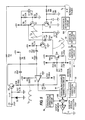
- FIGURE 5 is a circuit schematic of a parabola generator for developing a correction signal for North-South pincushion correction, according to an aspect of the invention.
- FIGURE 6 is a circuit schematic of a parabola generator for developing a correction signal for East-West pincushion correction, according to another aspect of the invention.
- FIGURE 7 illustrates a parabola waveform with non-linear vertical rate distortion, due to accumulated errors.
- the raster 40 shown in FIGURE 1 is an accurate and correct video display formed from a plurality of straight horizontal scan lines 42, which are of equal length and are parallel.
- the endpoints 44 of the scan lines all reside along vertical lines at the lateral sides of the raster display, perpendicular to the individual scan lines 42.
- Distortion of the raster can be produced due to distortions produced in the deflection circuits, in the curvature of the viewing surface or in the geometry of a projection system.
- Two examples of distortion in direct view and projection sets are the North-South (or top-bottom) pincushion distortion shown in FIGURE 2, and the East-West (side) pincushion distortion shown in FIGURE 3. Trapezoid and convergence distortion are not illustrated, but can also be expected in a projection set.
- the individual scan lines 42 of the raster display bow inwardly by an amount which is greatest at the top and bottom of the raster, and is less approaching the vertical center.
- the vertical deflection of the scanning electron beam can be adjusted by means of a parabolic shaped correction signal at the frequency of horizontal scanning to correct this distortion.
- the parabolic correction signal is modulated by a ramp at the vertical rate such that the correction parabola has a maximum positive (upward) amplitude at the top line of the raster, a zero amplitude at the vertical center scan line (which is not distorted ), and a maximum negative (downward) amplitude at the bottom scan line.
- the scan lines 42 at the top and bottom of the raster are longer than those at the vertical center, producing an inward bowing of the lines 44 at the sides of the raster, corresponding to the endpoints of the respective scan lines.
- This distortion can also be corrected by a parabolic correction signal, applied to modify horizontal deflection of the scanning beam.
- the parabola is at the vertical rate and the modulation is by a ramp at the horizontal rate.
- the distortion of the rasters of the three primary color CRTs may be different due to differences in scanning deflection and differences in projection angles between the projection axes and the axial center (the center of curvature) of the projection surface or screen.
- corresponding points of the three rasters as projected over one another do not precisely coincide, a convergence error occurs.
- FIGURE 4 illustrates in block form a circuit for producing a parabolic correction signal according to an aspect of the invention.
- the sawtooth shaped output signal 62 of a periodically reset ramp generator 84 is AC coupled to an active integrator 70 via a series capacitor 76.
- the integrator 70 comprises an operational amplifier 72 and a feedback capacitor 74, and produces the parabolic output 60 as shown.
- the timing errors change the average voltage level at the input to the integrator 70.
- the difference in average voltage level is processed by the integrator as a DC offset, which distorts the steady state shape of the parabolas.
- the average voltage error will require several vertical periods to dissipate. If the timing disturbance is periodic and repetitive, the average voltage level error in the integrator will not have an opportunity to dissipate. Instead, the error will accumulate, increasing the distortion of the parabola.
- the capacitor 74 forming the feedback path of the operational amplifier 72 of integrator 70 is coupled to an auxiliary resetting means 80, such as a transistor switch, operative to discharge the capacitor 74 during the occurrence of reset pulse 64.
- This periodic initialization prevents any accumulation of error, and assures that each parabola generated will start with a zero average voltage level, that is, with no unintended DC offset.
- Such a circuit in accordance with aspects of the invention is substantially insensitive to variations in the ramp signal 62.
- Timing disturbances at a vertical rate and multiples thereof can be coupled through the secondary windings of the integrated high voltage transformer.
- the timing disturbances can modulate the horizontal retrace pulses, by altering pulse width or frequency, or both.
- the horizontal retrace pulses are used to reset the ramp generating portion of the parabola generator at the horizontal rate.
- Some vertical deflection systems can produce significant phase distortion in all the secondary windings of the integrated high voltage transformer due to the switched mode of operation.
- the phase distortion can be most pronounced during the last part of vertical retrace, when the current through the switched elements, for example an SCR for effecting switched vertical retrace, is at its peak.
- the loading from this current modulates the horizontal retrace pulses, causing variation of pulse width or variation of frequency, or both, even from line to line.
- the ramp signal in a parabola generator for example, will not have a constant frequency, and the ramps will have different maximum amplitudes.
- Horizontal rate ramp signals can be integrated to produce a horizontal rate parabola for North-South pincushion correction, or used as a modulation signal for side pincushion correction. Variations in the start time of the ramps, the duration of the ramps and the maximum amplitude of the ramps will have a detrimental effect on the parabolas or modulate d signal envelopes. As a result of the variations in the horizontal retrace pulses, the horizontal rate parabola signal and/or modulation signal can vary in amplitude at the vertical rate.
- the integrator of a parabola generator as well as the ramp circuit, are reset by the reset pulse.
- the auxiliary reset function of the parabola signal dependably initializes, that is zeroes, the integrator before the beginning of each repetitive parabola. This eliminates undesirable periodic variation of the parabola signal from timing disturbances originating in vertical deflection systems and prevents distortion of the parabolas following restoration of vertical sync, for example after channel change.
- each repetitive parabola begins from whatever residual DC offset is processed by the integrator, as a result of a distorted ramp signal.
- FIGURE 5 illustrates a circuit schematic for implementing a correction circuit for North-South pincushion distortion, according to an aspect of the invention.
- the circuit comprises a ramp generator having a current source in the form of PNP transistor Q1, whose collector is coupled to integrating capacitor C2.
- Current source transistor Q1 charges capacitor C2 to form the ramp or sawtooth signal at the horizontal scanning rate.
- the emitter of Q2 is coupled to the positive supply through resistor R3.
- the level at the base of Q1 is fixed by a voltage divider comprising resistors R1 and R2.
- a capacitor C1 decouples the voltage divider junction (and the base of Q2) relative to the positive supply.
- the current supplied by current source Q1 is substantially constant, whereby integrating capacitor C2 charges constantly to obtain a ramp.
- Integrating capacitor C2 is discharged by switching transistor Q2 during the horizontal retrace.
- Resistors R4 and R5 couple the base of transistor Q2 to a reset signal from the horizontal deflection circuit 106, for example to the secondary winding of the IHVT that produces retrace pulses.
- Diode D1 clamps the base of Q2 with respect to ground.
- capacitor C2 is discharged and upon completion of the retrace pulse C2 begins to charge again, the signal at C2 therefore defining a sawtooth at the horizontal rate.
- the repetitive parabola signal developed at the output of operational amplifier U1 can be somewhat advanced in phase relative to generation of the raster, due to signal processing elsewhere in the television circuitry. Under these circumstances, it might be necessary to insert a phase delay, for example after the output of the operational amplifier, to compensate for the phase difference. Instead, resistor R8 adds a DC bias to the ramp signal, which raises the ramp signal level relative to a zero voltage level baseline. This has the effect of shifting the center of the parabola, as though the parabola had been delayed in time. The DC bias does alter the shape of the parabola to a small extent, but not enough to disturb the convergence correction.
- Capacitor C10 is discharged at the vertical rate by a switching means coupled to vertical retrace triggering means in vertical deflection circuit 90.
- the switching means includes transistor Q7, coupled to the integrating capacitor C10 through resistor R35.
- the base of transistor Q7 is coupled to the vertical deflection circuit 90 via series and parallel resistors R22 and R23, respectively, which set the appropriate level.
- the ramp at the vertical rate obtained at integrating capacitor C10 is coupled to a follower amplifier comprising PNP transistor Q8, whose emitter is coupled to the positive supply through resistor R24 and whose collector is grounded.
- the vertical sawtooth signal at the emitter of transistor Q8 can be used in other circuits.
- the emitter of Q8 is coupled to an NPN transistor Q11 via series capacitor C15.
- the base of transistor Q11 is biased by resistors R33 and R34.
- the feedback capacitor of an active integrator in a parabola generator is positively discharged by switch means at a point in time defined by a timing pulse, for example at the leading edge of a retrace pulse.
- the auxiliary reset function prevents distortion of the horizontal correction parabola by vertical rate phase and timing disturbances, for example those caused by switched mode operation of a vertical deflection system.
- the auxiliary reset function prevents distortion of the vertical correction parabola by vertical rate phase and timing disturbances, for example those caused by switched mode operation of a vertical deflection system, particularly at the time of vertical retrace.
- FIGURE 6 there is a further advantage in the embodiment of FIGURE 6.
- vertical retrace triggering is derived from the received video signal.
- a free running circuit in the vertical deflection circuit will provide internal vertical synchronizing pulses to prevent the raster from collapsing, although at a lower frequency than the vertical rate.
- the vertical ramp charges longer during the transient period following a channel change because the internal vertical period is longer, until a valid synchronizing signal is detected for the new channel.
- the auxiliary reset function prevents the longer charging of the vertical ramp during channel change from effecting the steady state values of the vertical rate parabolas generated after vertical sync is reestablished, so as to prevent convergence bounce.
- auxiliary reset function in the integrator responsive to a timing signal according to aspects of the invention, enables the steady state levels to be more closely maintained.
Landscapes
- Engineering & Computer Science (AREA)
- Physics & Mathematics (AREA)
- Mathematical Physics (AREA)
- Theoretical Computer Science (AREA)
- Multimedia (AREA)
- Signal Processing (AREA)
- Software Systems (AREA)
- Computer Hardware Design (AREA)
- General Physics & Mathematics (AREA)
- Details Of Television Scanning (AREA)
- Video Image Reproduction Devices For Color Tv Systems (AREA)
Applications Claiming Priority (2)
| Application Number | Priority Date | Filing Date | Title |
|---|---|---|---|
| US515972 | 1990-04-27 | ||
| US07/515,972 US5034664A (en) | 1990-04-27 | 1990-04-27 | Parabola generators with auxiliary reset function |
Publications (2)
| Publication Number | Publication Date |
|---|---|
| EP0454008A2 true EP0454008A2 (de) | 1991-10-30 |
| EP0454008A3 EP0454008A3 (en) | 1992-04-29 |
Family
ID=24053572
Family Applications (1)
| Application Number | Title | Priority Date | Filing Date |
|---|---|---|---|
| EP19910106404 Ceased EP0454008A3 (en) | 1990-04-27 | 1991-04-20 | Parabola generators with auxiliary reset function |
Country Status (6)
| Country | Link |
|---|---|
| US (1) | US5034664A (de) |
| EP (1) | EP0454008A3 (de) |
| JP (1) | JPH04229774A (de) |
| KR (1) | KR100210186B1 (de) |
| CA (1) | CA2039775C (de) |
| FI (1) | FI107104B (de) |
Cited By (2)
| Publication number | Priority date | Publication date | Assignee | Title |
|---|---|---|---|---|
| WO1996013118A1 (en) * | 1994-10-25 | 1996-05-02 | Philips Electronics N.V. | Deflection correction |
| EP0817473A3 (de) * | 1996-07-03 | 2001-10-17 | Thomson Consumer Electronics, Inc. | Vorrichtung zum Herstellen eines zusammengesetzten Synchronisationssignals |
Families Citing this family (17)
| Publication number | Priority date | Publication date | Assignee | Title |
|---|---|---|---|---|
| US5138238A (en) * | 1991-05-17 | 1992-08-11 | Thomson Consumer Electronics, Inc. | Arrangement for correcting beam landing location error in a video display |
| US5168199A (en) * | 1991-08-14 | 1992-12-01 | Loral Corporation | Horizontal linearity correction circuitry for cathode ray tube display |
| US5218275A (en) * | 1992-04-02 | 1993-06-08 | Thomson Consumer Electronics, Inc. | Beam landing location error correction arrangement |
| JPH07131672A (ja) * | 1993-10-28 | 1995-05-19 | Mitsubishi Electric Corp | ワイドアスペクトテレビジョン受像機 |
| US5644196A (en) * | 1993-12-08 | 1997-07-01 | Thomson Consumer Electronics, Inc. | Beam landing location error correction arrangement |
| JP3514317B2 (ja) * | 1993-12-08 | 2004-03-31 | トムソン コンシューマ エレクトロニクス インコーポレイテッド | ラスタ歪み補正配置 |
| JP3520551B2 (ja) * | 1994-03-22 | 2004-04-19 | ソニー株式会社 | 電子機器及び映像表示装置 |
| GB9405799D0 (en) * | 1994-03-24 | 1994-05-11 | Thomson Consumer Electronics | Shaped parabolic correction waveform for curved face plate display tube |
| US5491389A (en) * | 1994-05-11 | 1996-02-13 | Thomson Consumer Electronics, Inc. | Raster edge correction waveform |
| US5444338A (en) * | 1994-05-11 | 1995-08-22 | Thomson Consumer Electronics, Inc. | Left and right raster correction |
| US5508593A (en) * | 1994-05-11 | 1996-04-16 | Thomson Consumer Electronics, Inc. | Differential error convergence correction |
| US5847777A (en) * | 1994-05-11 | 1998-12-08 | George; John Barrett | Right-edge differential error convergence correction |
| US5528112A (en) * | 1994-12-08 | 1996-06-18 | Thomson Consumer Electronics, Inc. | Deflection correction signal generator |
| EP0743797A3 (de) * | 1995-05-19 | 1997-05-02 | Thomson Consumer Electronics | Differentielle Konvergenzkorrektur am rechten Rand |
| US6614193B2 (en) * | 2001-08-31 | 2003-09-02 | Thomson Licensing S.A. | Deflection current modulation circuit |
| US6717377B1 (en) * | 2001-10-31 | 2004-04-06 | Zilog, Inc. | Circuit and method for reducing east-west geometry mismatch between the top and bottom of a raster display |
| US7102302B2 (en) * | 2002-04-19 | 2006-09-05 | Thomson Licensing | Waveform generator for controlling an electron beam in a cathode ray tube |
Family Cites Families (8)
| Publication number | Priority date | Publication date | Assignee | Title |
|---|---|---|---|---|
| US3725726A (en) * | 1970-12-21 | 1973-04-03 | United Aircraft Corp | Crt geometry correction with zero offset |
| US3697778A (en) * | 1971-03-17 | 1972-10-10 | Tektronix Inc | Integrating circuit |
| US3842310A (en) * | 1971-04-01 | 1974-10-15 | Singer Co | Multiplying integrator circuit |
| NL7704062A (nl) * | 1977-04-14 | 1978-10-17 | Philips Nv | Schakeling voor het opwekken van een periodiek paraboolvormig signaal. |
| JPS6194836A (ja) * | 1984-10-16 | 1986-05-13 | Nhk Spring Co Ltd | テ−ルランプの車体へのシ−ル取付け構造 |
| JPH0681266B2 (ja) * | 1985-02-07 | 1994-10-12 | ソニー株式会社 | 垂直偏向装置 |
| JPS621374A (ja) * | 1985-06-27 | 1987-01-07 | Fujitsu General Ltd | 垂直偏向回路 |
| US4777411A (en) * | 1987-01-22 | 1988-10-11 | Zenith Electronics Corporation | Top/bottom active pincushion circuit with ringing inhibit |
-
1990
- 1990-04-27 US US07/515,972 patent/US5034664A/en not_active Expired - Fee Related
-
1991
- 1991-04-04 CA CA002039775A patent/CA2039775C/en not_active Expired - Fee Related
- 1991-04-19 FI FI911919A patent/FI107104B/fi active
- 1991-04-20 EP EP19910106404 patent/EP0454008A3/en not_active Ceased
- 1991-04-24 KR KR1019910006538A patent/KR100210186B1/ko not_active Expired - Fee Related
- 1991-04-26 JP JP3125346A patent/JPH04229774A/ja active Pending
Cited By (3)
| Publication number | Priority date | Publication date | Assignee | Title |
|---|---|---|---|---|
| WO1996013118A1 (en) * | 1994-10-25 | 1996-05-02 | Philips Electronics N.V. | Deflection correction |
| US5583400A (en) * | 1994-10-25 | 1996-12-10 | U.S. Phillips Corporation | Deflection correction |
| EP0817473A3 (de) * | 1996-07-03 | 2001-10-17 | Thomson Consumer Electronics, Inc. | Vorrichtung zum Herstellen eines zusammengesetzten Synchronisationssignals |
Also Published As
| Publication number | Publication date |
|---|---|
| FI911919A7 (fi) | 1991-10-28 |
| EP0454008A3 (en) | 1992-04-29 |
| KR910019397A (ko) | 1991-11-30 |
| FI107104B (fi) | 2001-05-31 |
| US5034664A (en) | 1991-07-23 |
| CA2039775C (en) | 1995-02-07 |
| JPH04229774A (ja) | 1992-08-19 |
| FI911919A0 (fi) | 1991-04-19 |
| KR100210186B1 (ko) | 1999-07-15 |
Similar Documents
| Publication | Publication Date | Title |
|---|---|---|
| US5034664A (en) | Parabola generators with auxiliary reset function | |
| US3668463A (en) | Raster correction circuit utilizing vertical deflection signals and high voltage representative signals to modulate the voltage regulator circuit | |
| US5399945A (en) | Raster distortion correction circuit | |
| EP0454007B1 (de) | Schaltung zur Korrektur der Kissenverzerrung mit Möwenflügelskompensation | |
| JP3464494B2 (ja) | ビデオ表示装置 | |
| EP0675641A1 (de) | Amplitudenregelschleife für parabelförmiges Korrektursignal | |
| US4423358A (en) | Horizontal deflection circuit with linearity correction | |
| KR100312332B1 (ko) | 빔랜딩위치에러보정장치 | |
| EP0528176B1 (de) | Linearitätskontrollvorrichtung für Horizontalablenkstufe | |
| US5115171A (en) | Raster distortion correction circuit | |
| US4198591A (en) | Vertical deflecting circuit | |
| CA2042480C (en) | Horizontal deflection circuit | |
| KR100363053B1 (ko) | 편향보정파형발생기및비디오디스플레이시스템 | |
| KR100316082B1 (ko) | 래스터왜곡보정장치 | |
| KR100433301B1 (ko) | 스위칭클램핑 | |
| JP3479089B2 (ja) | テレビジョン偏向装置 | |
| JPS61281677A (ja) | 左右糸巻歪補正回路 | |
| KR100245286B1 (ko) | 텔레비젼수상기의다이나믹포커싱전압발생회로 | |
| CA1230676A (en) | Constant width burst gate keying pulse generator | |
| JPS62243479A (ja) | 左右糸巻歪補正回路 | |
| HK1004316B (en) | Raster distortion correction circuit | |
| KR20010014054A (ko) | 수평편향회로 |
Legal Events
| Date | Code | Title | Description |
|---|---|---|---|
| PUAI | Public reference made under article 153(3) epc to a published international application that has entered the european phase |
Free format text: ORIGINAL CODE: 0009012 |
|
| AK | Designated contracting states |
Kind code of ref document: A2 Designated state(s): DE FR GB IT |
|
| PUAL | Search report despatched |
Free format text: ORIGINAL CODE: 0009013 |
|
| AK | Designated contracting states |
Kind code of ref document: A3 Designated state(s): DE FR GB IT |
|
| 17P | Request for examination filed |
Effective date: 19921005 |
|
| 17Q | First examination report despatched |
Effective date: 19940701 |
|
| APAB | Appeal dossier modified |
Free format text: ORIGINAL CODE: EPIDOS NOAPE |
|
| STAA | Information on the status of an ep patent application or granted ep patent |
Free format text: STATUS: THE APPLICATION HAS BEEN REFUSED |
|
| 18R | Application refused |
Effective date: 19951212 |
|
| APAF | Appeal reference modified |
Free format text: ORIGINAL CODE: EPIDOSCREFNE |