EP0454017A1 - Batterie d'accumulateurs à haute température - Google Patents
Batterie d'accumulateurs à haute température Download PDFInfo
- Publication number
- EP0454017A1 EP0454017A1 EP19910106417 EP91106417A EP0454017A1 EP 0454017 A1 EP0454017 A1 EP 0454017A1 EP 19910106417 EP19910106417 EP 19910106417 EP 91106417 A EP91106417 A EP 91106417A EP 0454017 A1 EP0454017 A1 EP 0454017A1
- Authority
- EP
- European Patent Office
- Prior art keywords
- storage battery
- battery according
- storage cells
- cooling
- temperature storage
- Prior art date
- Legal status (The legal status is an assumption and is not a legal conclusion. Google has not performed a legal analysis and makes no representation as to the accuracy of the status listed.)
- Granted
Links
- 210000000352 storage cell Anatomy 0.000 claims abstract description 80
- 238000001816 cooling Methods 0.000 claims abstract description 39
- 150000001875 compounds Chemical class 0.000 claims abstract description 17
- 238000010438 heat treatment Methods 0.000 claims abstract description 12
- 238000009413 insulation Methods 0.000 claims abstract description 5
- 210000004027 cell Anatomy 0.000 claims description 43
- 239000002826 coolant Substances 0.000 claims description 23
- 239000013590 bulk material Substances 0.000 claims description 17
- 238000005266 casting Methods 0.000 claims description 13
- 239000007788 liquid Substances 0.000 claims description 5
- 238000004382 potting Methods 0.000 claims description 5
- 239000004020 conductor Substances 0.000 claims description 3
- 239000011888 foil Substances 0.000 claims description 3
- 229910052751 metal Inorganic materials 0.000 claims description 3
- 239000002184 metal Substances 0.000 claims description 3
- 239000000463 material Substances 0.000 abstract description 6
- 238000005338 heat storage Methods 0.000 description 8
- 239000011159 matrix material Substances 0.000 description 6
- 229940126214 compound 3 Drugs 0.000 description 5
- 230000008878 coupling Effects 0.000 description 3
- 238000010168 coupling process Methods 0.000 description 3
- 238000005859 coupling reaction Methods 0.000 description 3
- 238000007789 sealing Methods 0.000 description 3
- 239000000126 substance Substances 0.000 description 3
- 230000015572 biosynthetic process Effects 0.000 description 2
- 230000004927 fusion Effects 0.000 description 2
- 239000011810 insulating material Substances 0.000 description 2
- KWGKDLIKAYFUFQ-UHFFFAOYSA-M lithium chloride Chemical compound [Li+].[Cl-] KWGKDLIKAYFUFQ-UHFFFAOYSA-M 0.000 description 2
- 230000008018 melting Effects 0.000 description 2
- 238000002844 melting Methods 0.000 description 2
- 239000000203 mixture Substances 0.000 description 2
- RYGMFSIKBFXOCR-UHFFFAOYSA-N Copper Chemical compound [Cu] RYGMFSIKBFXOCR-UHFFFAOYSA-N 0.000 description 1
- 239000006004 Quartz sand Substances 0.000 description 1
- VYPSYNLAJGMNEJ-UHFFFAOYSA-N Silicium dioxide Chemical compound O=[Si]=O VYPSYNLAJGMNEJ-UHFFFAOYSA-N 0.000 description 1
- 229910052783 alkali metal Inorganic materials 0.000 description 1
- 150000001340 alkali metals Chemical class 0.000 description 1
- 239000002585 base Substances 0.000 description 1
- 239000000969 carrier Substances 0.000 description 1
- 229910052798 chalcogen Inorganic materials 0.000 description 1
- 150000001787 chalcogens Chemical class 0.000 description 1
- 238000006243 chemical reaction Methods 0.000 description 1
- 239000007795 chemical reaction product Substances 0.000 description 1
- 229910052802 copper Inorganic materials 0.000 description 1
- 239000010949 copper Substances 0.000 description 1
- 230000002950 deficient Effects 0.000 description 1
- 230000000694 effects Effects 0.000 description 1
- 230000005496 eutectics Effects 0.000 description 1
- 239000000945 filler Substances 0.000 description 1
- 230000003179 granulation Effects 0.000 description 1
- 238000005469 granulation Methods 0.000 description 1
- TWNQGVIAIRXVLR-UHFFFAOYSA-N oxo(oxoalumanyloxy)alumane Chemical compound O=[Al]O[Al]=O TWNQGVIAIRXVLR-UHFFFAOYSA-N 0.000 description 1
- 239000011347 resin Substances 0.000 description 1
- 229920005989 resin Polymers 0.000 description 1
- 230000000284 resting effect Effects 0.000 description 1
- 229920001187 thermosetting polymer Polymers 0.000 description 1
Images


Classifications
-
- H—ELECTRICITY
- H01—ELECTRIC ELEMENTS
- H01M—PROCESSES OR MEANS, e.g. BATTERIES, FOR THE DIRECT CONVERSION OF CHEMICAL ENERGY INTO ELECTRICAL ENERGY
- H01M10/00—Secondary cells; Manufacture thereof
- H01M10/36—Accumulators not provided for in groups H01M10/05-H01M10/34
- H01M10/39—Accumulators not provided for in groups H01M10/05-H01M10/34 working at high temperature
- H01M10/3909—Sodium-sulfur cells
-
- H—ELECTRICITY
- H01—ELECTRIC ELEMENTS
- H01M—PROCESSES OR MEANS, e.g. BATTERIES, FOR THE DIRECT CONVERSION OF CHEMICAL ENERGY INTO ELECTRICAL ENERGY
- H01M10/00—Secondary cells; Manufacture thereof
- H01M10/60—Heating or cooling; Temperature control
- H01M10/61—Types of temperature control
- H01M10/613—Cooling or keeping cold
-
- H—ELECTRICITY
- H01—ELECTRIC ELEMENTS
- H01M—PROCESSES OR MEANS, e.g. BATTERIES, FOR THE DIRECT CONVERSION OF CHEMICAL ENERGY INTO ELECTRICAL ENERGY
- H01M10/00—Secondary cells; Manufacture thereof
- H01M10/60—Heating or cooling; Temperature control
- H01M10/61—Types of temperature control
- H01M10/615—Heating or keeping warm
-
- H—ELECTRICITY
- H01—ELECTRIC ELEMENTS
- H01M—PROCESSES OR MEANS, e.g. BATTERIES, FOR THE DIRECT CONVERSION OF CHEMICAL ENERGY INTO ELECTRICAL ENERGY
- H01M10/00—Secondary cells; Manufacture thereof
- H01M10/60—Heating or cooling; Temperature control
- H01M10/62—Heating or cooling; Temperature control specially adapted for specific applications
- H01M10/625—Vehicles
-
- H—ELECTRICITY
- H01—ELECTRIC ELEMENTS
- H01M—PROCESSES OR MEANS, e.g. BATTERIES, FOR THE DIRECT CONVERSION OF CHEMICAL ENERGY INTO ELECTRICAL ENERGY
- H01M10/00—Secondary cells; Manufacture thereof
- H01M10/60—Heating or cooling; Temperature control
- H01M10/64—Heating or cooling; Temperature control characterised by the shape of the cells
- H01M10/643—Cylindrical cells
-
- H—ELECTRICITY
- H01—ELECTRIC ELEMENTS
- H01M—PROCESSES OR MEANS, e.g. BATTERIES, FOR THE DIRECT CONVERSION OF CHEMICAL ENERGY INTO ELECTRICAL ENERGY
- H01M10/00—Secondary cells; Manufacture thereof
- H01M10/60—Heating or cooling; Temperature control
- H01M10/65—Means for temperature control structurally associated with the cells
- H01M10/655—Solid structures for heat exchange or heat conduction
- H01M10/6556—Solid parts with flow channel passages or pipes for heat exchange
- H01M10/6557—Solid parts with flow channel passages or pipes for heat exchange arranged between the cells
-
- H—ELECTRICITY
- H01—ELECTRIC ELEMENTS
- H01M—PROCESSES OR MEANS, e.g. BATTERIES, FOR THE DIRECT CONVERSION OF CHEMICAL ENERGY INTO ELECTRICAL ENERGY
- H01M10/00—Secondary cells; Manufacture thereof
- H01M10/60—Heating or cooling; Temperature control
- H01M10/65—Means for temperature control structurally associated with the cells
- H01M10/656—Means for temperature control structurally associated with the cells characterised by the type of heat-exchange fluid
- H01M10/6561—Gases
-
- H—ELECTRICITY
- H01—ELECTRIC ELEMENTS
- H01M—PROCESSES OR MEANS, e.g. BATTERIES, FOR THE DIRECT CONVERSION OF CHEMICAL ENERGY INTO ELECTRICAL ENERGY
- H01M10/00—Secondary cells; Manufacture thereof
- H01M10/60—Heating or cooling; Temperature control
- H01M10/65—Means for temperature control structurally associated with the cells
- H01M10/656—Means for temperature control structurally associated with the cells characterised by the type of heat-exchange fluid
- H01M10/6567—Liquids
-
- H—ELECTRICITY
- H01—ELECTRIC ELEMENTS
- H01M—PROCESSES OR MEANS, e.g. BATTERIES, FOR THE DIRECT CONVERSION OF CHEMICAL ENERGY INTO ELECTRICAL ENERGY
- H01M10/00—Secondary cells; Manufacture thereof
- H01M10/60—Heating or cooling; Temperature control
- H01M10/65—Means for temperature control structurally associated with the cells
- H01M10/658—Means for temperature control structurally associated with the cells by thermal insulation or shielding
-
- H—ELECTRICITY
- H01—ELECTRIC ELEMENTS
- H01M—PROCESSES OR MEANS, e.g. BATTERIES, FOR THE DIRECT CONVERSION OF CHEMICAL ENERGY INTO ELECTRICAL ENERGY
- H01M10/00—Secondary cells; Manufacture thereof
- H01M10/60—Heating or cooling; Temperature control
- H01M10/65—Means for temperature control structurally associated with the cells
- H01M10/659—Means for temperature control structurally associated with the cells by heat storage or buffering, e.g. heat capacity or liquid-solid phase changes or transition
-
- Y—GENERAL TAGGING OF NEW TECHNOLOGICAL DEVELOPMENTS; GENERAL TAGGING OF CROSS-SECTIONAL TECHNOLOGIES SPANNING OVER SEVERAL SECTIONS OF THE IPC; TECHNICAL SUBJECTS COVERED BY FORMER USPC CROSS-REFERENCE ART COLLECTIONS [XRACs] AND DIGESTS
- Y02—TECHNOLOGIES OR APPLICATIONS FOR MITIGATION OR ADAPTATION AGAINST CLIMATE CHANGE
- Y02E—REDUCTION OF GREENHOUSE GAS [GHG] EMISSIONS, RELATED TO ENERGY GENERATION, TRANSMISSION OR DISTRIBUTION
- Y02E60/00—Enabling technologies; Technologies with a potential or indirect contribution to GHG emissions mitigation
- Y02E60/10—Energy storage using batteries
Definitions
- the invention relates to a high-temperature storage battery according to the preamble of claim 1.
- Such high-temperature storage batteries which are constructed from electrochemical storage cells based on alkali metal and chalcogen, are increasingly being used as an energy source for electric vehicles.
- the hitherto known high-temperature storage batteries with electrochemical storage cells of the above-mentioned type work at a temperature of approximately 350 ° C.
- thermal insulation In order to avoid heat losses during the rest periods of the high-temperature storage batteries, they are surrounded by thermal insulation. This is limited by a double-walled housing, whereby the space between the walls is evacuated and filled with an insulating material. The interior of the insulation is used to hold the memory cells. In order to be able to hold the memory cells in the desired position, holders are provided.
- the brackets Since the storage cells must be cooled during the operation of the high-temperature storage battery, on the other hand during the rest periods of the battery, if necessary, to be kept at a minimum temperature with the aid of a heating device, the brackets must be designed in such a way that each storage cell experiences the required heating or cooling.
- the invention is therefore based on the object of providing a high-temperature storage battery which ensures secure mounting of the storage cells and at the same time enables each storage cell to be cooled or heated in the required manner.
- cooling channels are formed which adjoin the storage cells and the spaces between the storage cells.
- Such a cooling channel is formed, for example, by a recess in the housing of the storage cell.
- the depression extends over the entire length of the memory cell.
- Each cooling channel can be delimited by a wall that is convexly curved into the interior of the intermediate space. These convexly curved walls also extend over the entire length of the depression.
- the cooling system itself is closed. Direct contact between the heat transfer medium and the storage cell is avoided.
- heat is dissipated from the memory cell over the entire length of the memory cell, which reduces the vertical temperature gradients of the memory cells.
- the heat exchangers can be arranged on all boundary surfaces of the storage cell block or the cell matrix, as it is also called.
- the cell matrix can also be split into several parts in order to arrange heat exchangers between these parts. However, it is particularly advantageous to install the heat exchangers above and below the cell matrix, since practically all storage cells are the same distance from the heat exchanger. This is the only way to achieve an even temperature distribution in the cell matrix.
- the battery can be designed such that the inner wall of the insulation, which delimits the battery, simultaneously forms the outer delimiting wall of the heat exchanger.
- the bottom or the top surface of the cell matrix, which faces this boundary wall lies, can then form the inner boundary wall of the heat exchanger.
- rods made of a material that is a good conductor of heat can be embedded in the casting compound.
- the bars run parallel to the storage cells, are just as long as these and are also connected directly to the heat exchanger. It is possible to equip high-temperature storage batteries, which are designed for a particularly high continuous output, with a combined system of integrated cooling with a separate heat exchanger and integrated latent heat storage. In all cases, heating and maintaining the resting temperature of the high-temperature storage batteries is possible via electrically operated heating elements. These heating elements can be integrated into the heat exchanger.
- the storage cells 2 of each high-temperature storage battery 1 must be cooled during the operation of the high-temperature storage battery 1. If the high-temperature storage battery is one that is operated with a low continuous output, then latent heat storage devices can be used for cooling according to the invention.
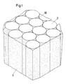
- a latent heat accumulator 4 is arranged in each intermediate space 5 that remains between 3 adjacent storage cells 2. This is limited by a cylindrical housing that is closed at the ends. The length of the cylindrical housing is adapted to the length of the memory cells 2.
- the latent heat accumulators 4 are arranged centrally in the spaces 5 and are also embedded in the sealing compound 3.
- the latent heat storage 4 are preferably filled (not shown here) with a material whose melting temperature is somewhat above the working temperature of the storage cells 2.
- the latent heat stores 4 are filled with a eutectic LiCl / KCl mixture. The heat that is required to melt this material is extracted from the storage cells 2, as a result of which they are cooled or their heat loss is compensated for.
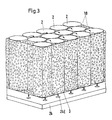
- FIG. 3 shows how a memory cell block 1B can be fixed in a high-temperature storage battery.
- the storage cells 2 are arranged in a battery box (not shown here) and a coarse-grained bulk material 3 is embedded. This consists of quartz sand or aluminum oxide. The grain size of the bulk material 3 is 0.5-2 mm. Remaining voids are also filled with the bulk material.
- a cooling medium which is gaseous or liquid, is passed through the bulk material 3 past the storage cells 2. As FIG. 3 shows, the cooling medium can be supplied to the memory cell block 1B via a distributor plate 24.
- the distributor plate 24 is provided with openings 24E.
- the size of the openings 24E and their distribution on the distributor plate 24 is determined by the amount of coolant to be supplied to each storage cell 2 in order to achieve sufficient cooling thereof. Since the bulk material 3 is coarse-grained, the cooling medium can be passed through without any problems. A uniform hydraulic resistance for the cooling medium is formed everywhere by a uniform granulation of the bulk material 3, so that the same is thereby distributed over all storage cells 2.
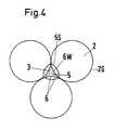
- cooling channels 6 are formed for this purpose, which directly adjoin the storage cells 2.
- An embodiment of these cooling channels 6 is shown in FIG. 4.
- the storage cells 2 are embedded in the bulk material 3 or the casting compound 3 in the same way as shown in FIGS. 1 and 3.
- the cooling channels 6 are arranged in the area of the interspaces 5 which arise between 3 adjacent storage cells 2 in each case.
- each storage cell 2 has a shell-shaped recess 6S in its housing 2G. This extends over the entire length of the storage cell 2.
- each cooling channel 6 a convexly curved wall 6W is arranged in front of each bowl-shaped recess 6S.
- This wall 6W also extends over the entire length of the storage cell 2.
- the coolant is distributed via collecting and distribution spaces as shown in FIG. 5.
- At least one distributor space 8, with which the cooling channels 6 are connected, is arranged on the underside of the memory cell block 1B. The coolant is introduced into it from the outside and is guided past the storage cells 2 via the cooling channels 6.
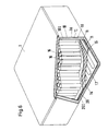
- FIG. 6 shows a high temperature storage battery 1, within which a memory cell block 1B is arranged.
- the storage cells 2 are cooled via one or more heat exchangers 11. In the exemplary embodiment shown here, only one heat exchanger 11 is provided. This is arranged on the underside of the memory cell block 1B. If the circumstances require it, a further heat exchanger (not shown here) can also be arranged above the storage cell block 1B. If necessary, further heat exchangers can be arranged on the lateral boundary surfaces of the memory cell block 1B.
- the inner housing part 1I is delimited by an outer and an inner housing part 1A, 1I.
- the dimensions of the inner housing part 1I are chosen to be smaller, so that a space 10 is created between the two housing parts 1A and 1I, which is evacuated and filled with insulating material 10I.
- a heat exchanger 11 is provided which is in heat-conducting contact with the bottom of the memory cell block 1B or the memory cells 2.
- the inner housing part 1I is double-walled in the region of its base. The heat exchanger 11 is arranged between this double bottom 20.
- the heat exchanger 11 is formed by bags 14 which are formed by metal foils. These are designed so that a cooling medium can flow through them. As shown in Figure 6, leads 15 are on the metal foils for the Coolant attached. If the coolant (not shown here) is pumped through the bags 14, the bags 14 lie firmly against the underside of the memory cell block 1B. In this way, a close heat-conducting contact between the storage cells 2 and the heat exchanger 11 is achieved.
- the inner boundary surface 20I of the inner housing part 1I can also be designed as a perforated plate (not shown here).
- the cooling medium flows through the bags 14 (as described above), they are pressed against the perforated plate.
- a close heat-conducting contact between the heat exchanger 11 and the memory cell block or the individual memory cells 2 is also formed here.
- heat exchangers 11 can also be installed in a corresponding manner via the storage cell block 1B (not shown here).
- the embodiment of the heat exchanger 11 described here and the formation of a close contact of the heat exchanger with the storage cells 2 is not limited to these embodiments. Rather, it encompasses all possibilities with which close contact between heat exchangers and storage cells is achieved.
- rods 16 made of a highly conductive material, preferably of copper, are embedded in the casting compound. These rods 16 are in direct contact with the heat exchangers or the heat exchanger 11.
- the high-temperature storage batteries which are provided for a particularly high continuous output
- a combined system consisting of indirect cooling, one or more separate heat exchangers and additional latent heat storage devices arranged between the storage cells.
- heating elements 17, for example can be integrated into the heat exchanger (s) 11, as shown in FIG. 6, which then provide the necessary heat supply.
Landscapes
- Engineering & Computer Science (AREA)
- Manufacturing & Machinery (AREA)
- Chemical & Material Sciences (AREA)
- Chemical Kinetics & Catalysis (AREA)
- Electrochemistry (AREA)
- General Chemical & Material Sciences (AREA)
- Secondary Cells (AREA)
- Battery Mounting, Suspending (AREA)
Applications Claiming Priority (2)
| Application Number | Priority Date | Filing Date | Title |
|---|---|---|---|
| DE4013269 | 1990-04-26 | ||
| DE19904013269 DE4013269A1 (de) | 1990-04-26 | 1990-04-26 | Hochtemperaturspeicherbatterie |
Publications (2)
| Publication Number | Publication Date |
|---|---|
| EP0454017A1 true EP0454017A1 (fr) | 1991-10-30 |
| EP0454017B1 EP0454017B1 (fr) | 1995-12-06 |
Family
ID=6405106
Family Applications (1)
| Application Number | Title | Priority Date | Filing Date |
|---|---|---|---|
| EP19910106417 Expired - Lifetime EP0454017B1 (fr) | 1990-04-26 | 1991-04-22 | Batterie d'accumulateurs à haute température |
Country Status (4)
| Country | Link |
|---|---|
| US (1) | US5158841A (fr) |
| EP (1) | EP0454017B1 (fr) |
| JP (1) | JPH04230962A (fr) |
| DE (2) | DE4013269A1 (fr) |
Cited By (19)
| Publication number | Priority date | Publication date | Assignee | Title |
|---|---|---|---|---|
| EP0588004A1 (fr) * | 1992-09-12 | 1994-03-23 | Bayerische Motoren Werke Aktiengesellschaft | Batterie de stockage d'énergie électrique, en particulier pour l'entraînement d'un véhicule |
| GB2295264A (en) * | 1994-11-18 | 1996-05-22 | Daimler Benz Ag | High temperature battery having cells in a thermally insulating case and immersed in a cooling liquid flowing around the cells to provide evaporative cooling |
| EP0730782A4 (fr) * | 1993-11-29 | 2000-01-19 | Store Heat & Produce Energy Inc | Appareil d'encapsulation pour controler la temperature de batteries |
| WO2007118437A1 (fr) * | 2006-04-19 | 2007-10-25 | Temic Automotive Electric Motors Gmbh | Échangeur thermique pour accumulateur d'énergie |
| WO2008104376A1 (fr) * | 2007-02-27 | 2008-09-04 | Daimler Ag | Boîtier de batterie |
| WO2008104356A1 (fr) * | 2007-02-27 | 2008-09-04 | Daimler Ag | Boîtier de batterie |
| WO2008104357A1 (fr) * | 2007-02-27 | 2008-09-04 | Daimler Ag | Batterie munie d'une plaque conductrice de chaleur |
| WO2008104374A1 (fr) * | 2007-02-27 | 2008-09-04 | Daimler Ag | Batterie comprenant une plaque thermoconductrice |
| EP2038960A4 (fr) * | 2006-05-31 | 2010-03-31 | Tesla Motors Inc | Système et méthode pour inhiber la propagation d'un événement exothermique |
| DE102009006216A1 (de) * | 2009-01-27 | 2010-07-29 | Modine Manufacturing Co., Racine | Kühlvorrichtung und Herstellungsverfahren |
| DE102009000392A1 (de) | 2009-01-23 | 2010-07-29 | Robert Bosch Gmbh | Klimatisierung elektrochemischer Energiespeicher mittels regelbarer Latentwärmespeicher |
| EP2393150A1 (fr) * | 2010-06-01 | 2011-12-07 | Battery Consult Sagl | Cellule de stockage d'énergie électrochimique rechargeable haute température |
| DE102007010742B4 (de) * | 2007-02-27 | 2012-12-06 | Daimler Ag | Zellverbund einer Batterie, Batterie und deren Verwendung |
| CN104538699A (zh) * | 2015-01-06 | 2015-04-22 | 重庆科鑫三佳车辆技术有限公司 | 电动汽车水冷电池模组以及水冷电池箱 |
| US9065103B2 (en) | 2005-05-12 | 2015-06-23 | Tesla Motors, Inc. | Battery mounting and cooling system |
| EP3176849A1 (fr) | 2015-12-03 | 2017-06-07 | Basf Se | Dispositif d'emmagasinage d'energie electrique |
| WO2019121970A1 (fr) * | 2017-12-20 | 2019-06-27 | Lion Smart Gmbh | Dispositif de batterie pour véhicule à propulsion électrique |
| WO2021254701A1 (fr) * | 2020-06-17 | 2021-12-23 | Bayerische Motoren Werke Aktiengesellschaft | Dispositif de maintien pour des cellules de batterie |
| EP4250409A1 (fr) * | 2022-03-23 | 2023-09-27 | tmax Holding GmbH | Dispositif de refroidissement ou d'aération de piles à combustible |
Families Citing this family (74)
| Publication number | Priority date | Publication date | Assignee | Title |
|---|---|---|---|---|
| GB2289976B (en) * | 1994-06-04 | 1997-01-15 | Rover Group | A battery |
| US5578393A (en) * | 1995-03-10 | 1996-11-26 | United States Advanced Battery Consortium | Thermal contact sheet for high temperature batteries |
| DE19526609A1 (de) * | 1995-07-21 | 1997-01-23 | Siemens Ag | Brennstoffzelle |
| GB9516850D0 (en) * | 1995-08-17 | 1995-10-18 | Programme 3 Patent Holdings | High temperature storage battery |
| DE19649691C2 (de) * | 1996-11-29 | 1998-10-15 | Siemens Ag | Flüssigkeitsgekühlte Brennstoffzellenbatterie sowie Verfahren zu deren Kühlung |
| FR2761203B1 (fr) * | 1997-03-24 | 1999-05-28 | Alsthom Cge Alcatel | Dispositif de gestion de la temperature d'une batterie de generateurs electrochimiques |
| DE19721348A1 (de) * | 1997-05-22 | 1998-11-26 | Varta Batterie | Mehrzelliger Akkumulator |
| US6210821B1 (en) * | 1998-12-28 | 2001-04-03 | International Fuel Cells Co, Llc | System for implementing operation and start-up of a vehicle which is powered by electricity from a fuel cell power plant |
| US6942944B2 (en) | 2000-02-29 | 2005-09-13 | Illinois Institute Of Technology | Battery system thermal management |
| US6468689B1 (en) * | 2000-02-29 | 2002-10-22 | Illinois Institute Of Technology | Thermal management of battery systems |
| US8273474B2 (en) * | 2000-02-29 | 2012-09-25 | Illinois Institute Of Technology | Battery system thermal management |
| US7592776B2 (en) | 2001-11-07 | 2009-09-22 | Quallion Llc | Energy storage device configured to discharge energy in response to unsafe conditions |
| US7443136B2 (en) * | 2002-01-09 | 2008-10-28 | Quallion Llc | Method and device employing heat absorber for limiting battery temperature spikes |
| US7189473B2 (en) * | 2003-06-03 | 2007-03-13 | Eastway Fair Company Limited | Battery venting system |
| WO2006086156A2 (fr) * | 2005-02-08 | 2006-08-17 | Valence Technology, Inc. | Methode et appareil pour dissiper la chaleur generee par une pile electrochimique secondaire |
| DE102005017648B4 (de) * | 2005-04-15 | 2008-01-10 | Daimlerchrysler Ag | Flüssigkeitsgekühlte Batterie und Verfahren zum Betreiben einer solchen |
| US20110201253A1 (en) * | 2005-08-25 | 2011-08-18 | Michael Stude | Cleavage enhancing brassiere |
| JP4945963B2 (ja) * | 2005-08-31 | 2012-06-06 | トヨタ自動車株式会社 | 燃料電池 |
| FR2915320B1 (fr) * | 2007-04-19 | 2010-10-22 | Socite De Vehicules Electr | Batterie electrique comprenant des modules de conditionnement thermique enrobes par une matrice structurelle |
| US7433794B1 (en) * | 2007-07-18 | 2008-10-07 | Tesla Motors, Inc. | Mitigation of propagation of thermal runaway in a multi-cell battery pack |
| DE102007063187B3 (de) * | 2007-12-20 | 2009-04-02 | Daimler Ag | Batterie mit einer Kühlplatte und Verfahren zur Herstellung einer Batterie |
| DE102007063194B4 (de) * | 2007-12-20 | 2010-03-25 | Daimler Ag | Zellverbund, Batterie mit einem Zellverbund sowie Verfahren zur Herstellung eines Zellverbundes |
| DE102007063174B4 (de) * | 2007-12-20 | 2010-02-25 | Daimler Ag | Batterie mit mehreren parallel und/oder seriell miteinander verschalteten Einzelzellen und einer Wärmeleitplatte zum Temperieren der Batterie und Verwendung der Batterie |
| US20090169983A1 (en) * | 2007-12-27 | 2009-07-02 | Ajith Kuttannair Kumar | Battery with a phase-changing material |
| DE102008034889B4 (de) * | 2008-07-26 | 2011-06-30 | Daimler AG, 70327 | Batterie mit einer in einem Batteriegehäuse angeordneten Wärmeleitplatte zum Temperieren der Batterie und Verfahren zur Herstellung einer Batterie |
| DE102008034857A1 (de) * | 2008-07-26 | 2010-02-04 | Daimler Ag | Verfahren und Vorrichtung zum Betrieb eines Fahrzeuges |
| US20100028758A1 (en) * | 2008-08-04 | 2010-02-04 | Eaves Stephen S | Suppression of battery thermal runaway |
| DE102008056787A1 (de) * | 2008-11-11 | 2010-05-12 | Cord-Henrich Dr. Dustmann | Elektrofahrzeugheizvorrichtung |
| DE102008059955B4 (de) | 2008-12-02 | 2011-07-21 | Daimler AG, 70327 | Verfahren zur Herstellung einer Kühlplatte mit einem integrierten Kühlkanal für eine Batterie und Verwendung einer Kühlplatte |
| DE102008059954B4 (de) | 2008-12-02 | 2013-11-07 | Daimler Ag | Batterie mit mehreren parallel und/oder seriell miteinander elektrisch verschalteten Batteriezellen und einer Kühlvorrichtung und die Verwendung der Batterie |
| US20100291426A1 (en) * | 2009-05-15 | 2010-11-18 | Sinoelectric Powertrain Corporation | Flexible fusible link, systems, and methods |
| US20100291427A1 (en) * | 2009-05-15 | 2010-11-18 | Sinoelectric Powertrain Corporation | Modular powertrain, systems, and methods |
| US20100291418A1 (en) * | 2009-05-15 | 2010-11-18 | Sinoelectric Powertrain Corporation | Battery packs, systems, and methods |
| US20100291419A1 (en) * | 2009-05-15 | 2010-11-18 | Sinoelectric Powertrain Corporation | Battery pack heat exchanger, systems, and methods |
| EP2522047A1 (fr) | 2010-01-08 | 2012-11-14 | Dow Global Technologies LLC | Gestion thermique de cellule électrochimique par combinaison de fluide de transfert de chaleur et de matériau à changement de phase |
| WO2011092773A1 (fr) * | 2010-01-29 | 2011-08-04 | パナソニック株式会社 | Module de pile |
| DE102010013012A1 (de) * | 2010-03-26 | 2011-09-29 | Dr. Ing. H.C. F. Porsche Aktiengesellschaft | Energiespeicher für ein Kraftfahrzeug |
| WO2011127319A1 (fr) | 2010-04-08 | 2011-10-13 | Sinoelectric Powertrain Inc | Appareil pour préchauffer un bloc-batterie avant la charge |
| US8659261B2 (en) | 2010-07-14 | 2014-02-25 | Sinoelectric Powertrain Corporation | Battery pack enumeration method |
| US9172120B2 (en) | 2010-07-14 | 2015-10-27 | Sinoelectric Powertrain Corporation | Battery pack fault communication and handling |
| DE102010046530B4 (de) * | 2010-09-24 | 2022-11-03 | Volkswagen Ag | Akkumulatormodul |
| US8486283B2 (en) | 2010-11-02 | 2013-07-16 | Sinoelectric Powertrain Corporation | Method of making fusible links |
| US8641273B2 (en) | 2010-11-02 | 2014-02-04 | Sinoelectric Powertrain Corporation | Thermal interlock for battery pack, device, system and method |
| CN103563124B (zh) * | 2011-05-30 | 2016-08-17 | 松下知识产权经营株式会社 | 电池块及其制造方法 |
| JP5772244B2 (ja) * | 2011-06-03 | 2015-09-02 | 株式会社豊田自動織機 | 蓄電装置 |
| DE102011086799A1 (de) * | 2011-11-22 | 2013-05-23 | Robert Bosch Gmbh | System mit einem Handwerkzeugkoffer und einem Handwerkzeugakku |
| US8808914B2 (en) | 2012-01-13 | 2014-08-19 | Energy Power Systems, LLC | Lead-acid battery design having versatile form factor |
| US9263721B2 (en) | 2012-01-13 | 2016-02-16 | Energy Power Systems LLC | Lead-acid battery design having versatile form factor |
| US9595360B2 (en) | 2012-01-13 | 2017-03-14 | Energy Power Systems LLC | Metallic alloys having amorphous, nano-crystalline, or microcrystalline structure |
| ITBO20120057A1 (it) * | 2012-02-07 | 2013-08-08 | Ferrari Spa | Sistema di accumulo di energia elettrica per un veicolo con propulsione elettrica e presentante batteria chimiche cilindriche annegate in una matrice di supporto |
| DE102012018040A1 (de) | 2012-09-13 | 2014-03-13 | Daimler Ag | Einzelzelle für eine elektrochemische Batterie, elektrochemische Batterie und Verfahren zum Betrieb einer Einzelzelle für eine elektrochemische Batterie |
| DE102013102867A1 (de) | 2013-03-20 | 2014-10-09 | Dr. Ing. H.C. F. Porsche Aktiengesellschaft | Temperiervorrichtung |
| ITMI20132047A1 (it) * | 2013-12-09 | 2015-06-10 | Fiamm Energy Storage Solutions S P A | Apparato per il controllo della temperatura nelle batterie costituite da celle ad alta temperatura basate sul sodio |
| DE102014111645A1 (de) | 2014-08-14 | 2016-02-18 | Jobst H. KERSPE | Batteriegehäuse |
| DE102015203997A1 (de) * | 2015-03-05 | 2016-09-08 | Siemens Aktiengesellschaft | Füllmaterial und Abstandshalter bei Batterien |
| PL3196956T3 (pl) * | 2016-01-21 | 2019-01-31 | KÖNIG METALL GmbH & Co. KG | Sposób wytwarzania obudowy akumulatora |
| DE102016106021A1 (de) | 2016-01-21 | 2017-07-27 | Jobst H. KERSPE | Verfahren zur Herstellung eines Batteriegehäuses |
| DE102016214640A1 (de) * | 2016-08-08 | 2018-02-08 | Audi Ag | Batteriemodul für eine Batterie eines Kraftfahrzeugs und Kraftfahrzeug |
| DE102016115627A1 (de) | 2016-08-23 | 2018-03-01 | Benteler Automobiltechnik Gmbh | Batterieträger mit Kühlsystem |
| US10461383B2 (en) * | 2017-08-07 | 2019-10-29 | Ford Global Technologies, Llc | Battery enclosure having a composite structure with a coolant channel |
| DE102018205649A1 (de) * | 2018-04-13 | 2019-10-17 | Lion Smart Gmbh | Temperiervorrichtung für die temperierung einer batterievorrichtung |
| AT521295B1 (de) * | 2018-06-12 | 2020-02-15 | Miba Ag | Akkumulator |
| KR20210156832A (ko) * | 2019-04-15 | 2021-12-27 | 로베르트 보쉬 게엠베하 | 전지 냉각을 용이하게 하는 관형 스페이서를 갖는 배터리 모듈 |
| JP2023513850A (ja) | 2019-12-11 | 2023-04-03 | ブレン-トロニクス,インコーポレイテッド | 充電式電池用の熱管理システム |
| FR3106438B1 (fr) * | 2020-01-21 | 2022-01-28 | Valeo Systemes Thermiques | Dispositif de refroidissement d’un composant électrique et/ou électronique susceptible de dégager de la chaleur en fonctionnement |
| ES2951185T3 (es) * | 2020-07-10 | 2023-10-18 | Contemporary Amperex Technology Co Ltd | Batería y aparato relacionado, método de fabricación y dispositivo de fabricación de la misma |
| US11799151B1 (en) * | 2020-08-20 | 2023-10-24 | Moog Inc. | Vehicle battery cell cooling assembly |
| DE102021105375A1 (de) | 2021-03-05 | 2022-09-08 | Volocopter Gmbh | Batteriekühlvorrichtung und Verfahren zur Kühlung einer Batteriezelle eines elektrisch angetriebenen Fluggerätes |
| DE102021119070A1 (de) * | 2021-07-22 | 2023-01-26 | Bayerische Motoren Werke Aktiengesellschaft | Fortbewegungsmittel, Verfahren und Anordnung für einen elektrochemischen Energiespeicher |
| CA3227198A1 (fr) | 2021-07-28 | 2023-02-02 | Peter HEIDEBRECHT | Dispositif de stockage d'energie electrochimique |
| DE102022103336A1 (de) | 2022-02-14 | 2023-08-17 | Bayerische Motoren Werke Aktiengesellschaft | Elektrischer Energiespeicher mit Entgasungsraum |
| DE102022103744A1 (de) | 2022-02-17 | 2023-08-17 | Bayerische Motoren Werke Aktiengesellschaft | Verfahren zum zumindest partiellen Rezyklieren und/oder Reparieren eines elektrischen Energiespeichers |
| DE102022132438A1 (de) * | 2022-12-07 | 2024-06-13 | Bayerische Motoren Werke Aktiengesellschaft | Energiespeichervorrichtung für ein Kraftfahrzeug |
| US12463268B2 (en) | 2023-01-11 | 2025-11-04 | Ford Global Technologies, Llc | Volume filler for immersion cooling battery array designs |
Citations (3)
| Publication number | Priority date | Publication date | Assignee | Title |
|---|---|---|---|---|
| EP0065248A1 (fr) * | 1981-05-15 | 1982-11-24 | BROWN, BOVERI & CIE Aktiengesellschaft | Batterie fonctionnant à haute température |
| GB2153136A (en) * | 1984-01-20 | 1985-08-14 | Lilliwyte Sa | Temperature controlled na-s cell |
| DE3717266A1 (de) * | 1986-05-23 | 1987-11-26 | Univ Ramot | Mehrzellenbatterie |
Family Cites Families (5)
| Publication number | Priority date | Publication date | Assignee | Title |
|---|---|---|---|---|
| US1607460A (en) * | 1922-05-04 | 1926-11-16 | Nat Carbon Co Inc | Dry-cell battery |
| US3784411A (en) * | 1971-07-06 | 1974-01-08 | Mallory & Co Inc P R | Electric cell battery with plastic webbing spacer for fast and complete epoxy encapsulation |
| DE2548813B2 (de) * | 1975-10-31 | 1978-03-23 | Accumulatorenwerk Hoppecke Carl Zoellner & Sohn, 5000 Koeln | Verfahren zum Festlegen von Plattensatzen in Zellen von Akkumulatoren |
| JPS5648072A (en) * | 1979-09-27 | 1981-05-01 | Shin Kobe Electric Mach Co Ltd | Fabrication of lead acid battery |
| DE3247969C2 (de) * | 1982-12-24 | 1987-04-02 | Brown, Boveri & Cie Ag, 6800 Mannheim | Hochtemperaturspeicherbatterie |
-
1990
- 1990-04-26 DE DE19904013269 patent/DE4013269A1/de not_active Withdrawn
-
1991
- 1991-04-22 EP EP19910106417 patent/EP0454017B1/fr not_active Expired - Lifetime
- 1991-04-22 DE DE59107005T patent/DE59107005D1/de not_active Expired - Fee Related
- 1991-04-25 JP JP3095308A patent/JPH04230962A/ja active Pending
- 1991-04-26 US US07/692,320 patent/US5158841A/en not_active Expired - Fee Related
Patent Citations (3)
| Publication number | Priority date | Publication date | Assignee | Title |
|---|---|---|---|---|
| EP0065248A1 (fr) * | 1981-05-15 | 1982-11-24 | BROWN, BOVERI & CIE Aktiengesellschaft | Batterie fonctionnant à haute température |
| GB2153136A (en) * | 1984-01-20 | 1985-08-14 | Lilliwyte Sa | Temperature controlled na-s cell |
| DE3717266A1 (de) * | 1986-05-23 | 1987-11-26 | Univ Ramot | Mehrzellenbatterie |
Cited By (28)
| Publication number | Priority date | Publication date | Assignee | Title |
|---|---|---|---|---|
| EP0588004A1 (fr) * | 1992-09-12 | 1994-03-23 | Bayerische Motoren Werke Aktiengesellschaft | Batterie de stockage d'énergie électrique, en particulier pour l'entraînement d'un véhicule |
| EP0730782A4 (fr) * | 1993-11-29 | 2000-01-19 | Store Heat & Produce Energy Inc | Appareil d'encapsulation pour controler la temperature de batteries |
| GB2295264A (en) * | 1994-11-18 | 1996-05-22 | Daimler Benz Ag | High temperature battery having cells in a thermally insulating case and immersed in a cooling liquid flowing around the cells to provide evaporative cooling |
| FR2727247A1 (fr) * | 1994-11-18 | 1996-05-24 | Daimler Benz Ag | Dispositif de refroidissement pour une batterie constituee de plusieurs elements |
| US9065103B2 (en) | 2005-05-12 | 2015-06-23 | Tesla Motors, Inc. | Battery mounting and cooling system |
| WO2007118437A1 (fr) * | 2006-04-19 | 2007-10-25 | Temic Automotive Electric Motors Gmbh | Échangeur thermique pour accumulateur d'énergie |
| KR101379830B1 (ko) * | 2006-04-19 | 2014-04-01 | 테믹 오토모티브 일렉트릭 모터스 게엠베하 | 에너지 저장 장치용 열 교환기 |
| US8105708B2 (en) | 2006-04-19 | 2012-01-31 | Temic Automotive Electric Motors Gmbh | Heat exchanger for an energy storage device |
| EP2038960A4 (fr) * | 2006-05-31 | 2010-03-31 | Tesla Motors Inc | Système et méthode pour inhiber la propagation d'un événement exothermique |
| WO2008104357A1 (fr) * | 2007-02-27 | 2008-09-04 | Daimler Ag | Batterie munie d'une plaque conductrice de chaleur |
| WO2008104376A1 (fr) * | 2007-02-27 | 2008-09-04 | Daimler Ag | Boîtier de batterie |
| WO2008104356A1 (fr) * | 2007-02-27 | 2008-09-04 | Daimler Ag | Boîtier de batterie |
| DE102007010742B4 (de) * | 2007-02-27 | 2012-12-06 | Daimler Ag | Zellverbund einer Batterie, Batterie und deren Verwendung |
| WO2008104374A1 (fr) * | 2007-02-27 | 2008-09-04 | Daimler Ag | Batterie comprenant une plaque thermoconductrice |
| DE102009000392A1 (de) | 2009-01-23 | 2010-07-29 | Robert Bosch Gmbh | Klimatisierung elektrochemischer Energiespeicher mittels regelbarer Latentwärmespeicher |
| DE102009006216B4 (de) * | 2009-01-27 | 2018-11-22 | Modine Manufacturing Co. | Kühlvorrichtung und Herstellungsverfahren |
| DE102009006216A1 (de) * | 2009-01-27 | 2010-07-29 | Modine Manufacturing Co., Racine | Kühlvorrichtung und Herstellungsverfahren |
| EP2393150A1 (fr) * | 2010-06-01 | 2011-12-07 | Battery Consult Sagl | Cellule de stockage d'énergie électrochimique rechargeable haute température |
| WO2011150528A1 (fr) * | 2010-06-01 | 2011-12-08 | Battery Consult Sagl | Cellule de stockage d'énergie électrochimique rechargeable à haute température |
| CN104538699A (zh) * | 2015-01-06 | 2015-04-22 | 重庆科鑫三佳车辆技术有限公司 | 电动汽车水冷电池模组以及水冷电池箱 |
| CN104538699B (zh) * | 2015-01-06 | 2017-01-18 | 重庆科鑫三佳车辆技术有限公司 | 电动汽车水冷电池模组以及水冷电池箱 |
| EP3176849A1 (fr) | 2015-12-03 | 2017-06-07 | Basf Se | Dispositif d'emmagasinage d'energie electrique |
| WO2017093386A1 (fr) * | 2015-12-03 | 2017-06-08 | Basf Se | Dispositif de stockage d'énergie électrique |
| WO2019121970A1 (fr) * | 2017-12-20 | 2019-06-27 | Lion Smart Gmbh | Dispositif de batterie pour véhicule à propulsion électrique |
| US11855268B2 (en) | 2017-12-20 | 2023-12-26 | Lion Smart Gmbh | Battery apparatus for an electrically driven vehicle |
| WO2021254701A1 (fr) * | 2020-06-17 | 2021-12-23 | Bayerische Motoren Werke Aktiengesellschaft | Dispositif de maintien pour des cellules de batterie |
| CN115280580A (zh) * | 2020-06-17 | 2022-11-01 | 宝马股份公司 | 用于电池单体的保持装置 |
| EP4250409A1 (fr) * | 2022-03-23 | 2023-09-27 | tmax Holding GmbH | Dispositif de refroidissement ou d'aération de piles à combustible |
Also Published As
| Publication number | Publication date |
|---|---|
| DE59107005D1 (de) | 1996-01-18 |
| US5158841A (en) | 1992-10-27 |
| EP0454017B1 (fr) | 1995-12-06 |
| DE4013269A1 (de) | 1991-10-31 |
| JPH04230962A (ja) | 1992-08-19 |
Similar Documents
| Publication | Publication Date | Title |
|---|---|---|
| EP0454017B1 (fr) | Batterie d'accumulateurs à haute température | |
| EP0109543B1 (fr) | Batterie d'accumulateurs fonctionnant à haute température | |
| AT521526B1 (de) | Batterie | |
| EP1508182B1 (fr) | Batterie comportant au moins une cellule de stockage electrochimique et un dispositif de refroidissement | |
| DE3247969C2 (de) | Hochtemperaturspeicherbatterie | |
| EP4046231B1 (fr) | Dispositif de logement pour batterie de traction à fonction de refroidissement à base de fluide comprenant un dispositif d'évaporation à microcanaux | |
| DE60004269T2 (de) | Elektronische baugruppe mit hohem kühlungsvermögen | |
| DE68904585T2 (de) | Gehaeuse fuer unterwassereinrichtung. | |
| EP2377184B1 (fr) | Dispositif d'alimentation en tension pour un véhicule avec une dissipation thermique améliorée | |
| WO2018024483A1 (fr) | Dispositif d'équilibrage de température pour boîtier de batterie d'un véhicule | |
| EP0588004A1 (fr) | Batterie de stockage d'énergie électrique, en particulier pour l'entraînement d'un véhicule | |
| DE202010002352U1 (de) | Elektrochemischer Energiespeicher | |
| DE102020111006A1 (de) | Thermomanagementsystem für eine Batterie sowie Kraftfahrzeug und Verfahren hierzu | |
| DE102011119174A1 (de) | Vapor Chamber | |
| DE19849491C1 (de) | Elektrochemischer Energiespeicher | |
| DE19724020A1 (de) | Wärmestrahlungsgerät mit Wärmerohr für Energiespeicherbatteriegeräte | |
| DE102010063057A1 (de) | Batteriesystem für ein Kraftfahrzeug mit wenigstens einer elektrochemischen Zelle und wenigstens einem Latentwärmespeicher | |
| DE2730161A1 (de) | Vorrichtung zum ziehen eines kristalls | |
| DE112017006745B4 (de) | Wärmeaustauschvorrichtung, insbesondere für die Wärmeregelung einer Kraftfahrzeugbatterie | |
| DE4441162A1 (de) | Kühleinrichtung für eine aus mehreren Zellen aufgebaute Batterie | |
| DE3224161C2 (fr) | ||
| DE3990275C1 (de) | Wärmespeicher, insbesondere Latentwärmespeicher für Kraftfahrzeuge | |
| AT521295B1 (de) | Akkumulator | |
| DE112017006744B4 (de) | Wärmetauscher mit zwei Rohrreihen zur Wärmeregelung einer Kraftfahrzeugbatterie | |
| DE102019120498A1 (de) | Energiespeichersystem |
Legal Events
| Date | Code | Title | Description |
|---|---|---|---|
| PUAI | Public reference made under article 153(3) epc to a published international application that has entered the european phase |
Free format text: ORIGINAL CODE: 0009012 |
|
| AK | Designated contracting states |
Kind code of ref document: A1 Designated state(s): DE ES FR GB IT |
|
| 17P | Request for examination filed |
Effective date: 19920211 |
|
| 17Q | First examination report despatched |
Effective date: 19940131 |
|
| GRAA | (expected) grant |
Free format text: ORIGINAL CODE: 0009210 |
|
| AK | Designated contracting states |
Kind code of ref document: B1 Designated state(s): DE ES FR GB IT |
|
| PG25 | Lapsed in a contracting state [announced via postgrant information from national office to epo] |
Ref country code: ES Free format text: THE PATENT HAS BEEN ANNULLED BY A DECISION OF A NATIONAL AUTHORITY Effective date: 19951206 |
|
| ET | Fr: translation filed | ||
| REF | Corresponds to: |
Ref document number: 59107005 Country of ref document: DE Date of ref document: 19960118 |
|
| ITF | It: translation for a ep patent filed | ||
| PGFP | Annual fee paid to national office [announced via postgrant information from national office to epo] |
Ref country code: GB Payment date: 19960130 Year of fee payment: 6 Ref country code: FR Payment date: 19960130 Year of fee payment: 6 |
|
| GBT | Gb: translation of ep patent filed (gb section 77(6)(a)/1977) |
Effective date: 19960122 |
|
| PGFP | Annual fee paid to national office [announced via postgrant information from national office to epo] |
Ref country code: DE Payment date: 19960229 Year of fee payment: 6 |
|
| PLBE | No opposition filed within time limit |
Free format text: ORIGINAL CODE: 0009261 |
|
| STAA | Information on the status of an ep patent application or granted ep patent |
Free format text: STATUS: NO OPPOSITION FILED WITHIN TIME LIMIT |
|
| 26N | No opposition filed | ||
| PG25 | Lapsed in a contracting state [announced via postgrant information from national office to epo] |
Ref country code: GB Effective date: 19970422 |
|
| GBPC | Gb: european patent ceased through non-payment of renewal fee |
Effective date: 19970422 |
|
| PG25 | Lapsed in a contracting state [announced via postgrant information from national office to epo] |
Ref country code: FR Free format text: LAPSE BECAUSE OF NON-PAYMENT OF DUE FEES Effective date: 19971231 |
|
| PG25 | Lapsed in a contracting state [announced via postgrant information from national office to epo] |
Ref country code: DE Free format text: LAPSE BECAUSE OF NON-PAYMENT OF DUE FEES Effective date: 19980101 |
|
| REG | Reference to a national code |
Ref country code: FR Ref legal event code: ST |
|
| PG25 | Lapsed in a contracting state [announced via postgrant information from national office to epo] |
Ref country code: IT Free format text: LAPSE BECAUSE OF NON-PAYMENT OF DUE FEES;WARNING: LAPSES OF ITALIAN PATENTS WITH EFFECTIVE DATE BEFORE 2007 MAY HAVE OCCURRED AT ANY TIME BEFORE 2007. THE CORRECT EFFECTIVE DATE MAY BE DIFFERENT FROM THE ONE RECORDED. Effective date: 20050422 |