EP0454041A1 - Transmission Control System - Google Patents
Transmission Control System Download PDFInfo
- Publication number
- EP0454041A1 EP0454041A1 EP91106487A EP91106487A EP0454041A1 EP 0454041 A1 EP0454041 A1 EP 0454041A1 EP 91106487 A EP91106487 A EP 91106487A EP 91106487 A EP91106487 A EP 91106487A EP 0454041 A1 EP0454041 A1 EP 0454041A1
- Authority
- EP
- European Patent Office
- Prior art keywords
- signals
- throttle position
- producing
- vehicle
- automatic
- Prior art date
- Legal status (The legal status is an assumption and is not a legal conclusion. Google has not performed a legal analysis and makes no representation as to the accuracy of the status listed.)
- Ceased
Links
- 230000005540 biological transmission Effects 0.000 title claims abstract description 42
- 230000004044 response Effects 0.000 claims description 2
- 238000010276 construction Methods 0.000 description 4
- 238000010586 diagram Methods 0.000 description 3
- 230000004048 modification Effects 0.000 description 3
- 238000012986 modification Methods 0.000 description 3
- 230000007423 decrease Effects 0.000 description 2
- 230000000994 depressogenic effect Effects 0.000 description 2
- 230000007246 mechanism Effects 0.000 description 1
- 230000007935 neutral effect Effects 0.000 description 1
- 230000008520 organization Effects 0.000 description 1
Images


Classifications
-
- F—MECHANICAL ENGINEERING; LIGHTING; HEATING; WEAPONS; BLASTING
- F16—ENGINEERING ELEMENTS AND UNITS; GENERAL MEASURES FOR PRODUCING AND MAINTAINING EFFECTIVE FUNCTIONING OF MACHINES OR INSTALLATIONS; THERMAL INSULATION IN GENERAL
- F16H—GEARING
- F16H61/00—Control functions within control units of change-speed- or reversing-gearings for conveying rotary motion ; Control of exclusively fluid gearing, friction gearing, gearings with endless flexible members or other particular types of gearing
- F16H61/02—Control functions within control units of change-speed- or reversing-gearings for conveying rotary motion ; Control of exclusively fluid gearing, friction gearing, gearings with endless flexible members or other particular types of gearing characterised by the signals used
- F16H61/0202—Control functions within control units of change-speed- or reversing-gearings for conveying rotary motion ; Control of exclusively fluid gearing, friction gearing, gearings with endless flexible members or other particular types of gearing characterised by the signals used the signals being electric
- F16H61/0204—Control functions within control units of change-speed- or reversing-gearings for conveying rotary motion ; Control of exclusively fluid gearing, friction gearing, gearings with endless flexible members or other particular types of gearing characterised by the signals used the signals being electric for gearshift control, e.g. control functions for performing shifting or generation of shift signal
- F16H61/0213—Control functions within control units of change-speed- or reversing-gearings for conveying rotary motion ; Control of exclusively fluid gearing, friction gearing, gearings with endless flexible members or other particular types of gearing characterised by the signals used the signals being electric for gearshift control, e.g. control functions for performing shifting or generation of shift signal characterised by the method for generating shift signals
-
- F—MECHANICAL ENGINEERING; LIGHTING; HEATING; WEAPONS; BLASTING
- F16—ENGINEERING ELEMENTS AND UNITS; GENERAL MEASURES FOR PRODUCING AND MAINTAINING EFFECTIVE FUNCTIONING OF MACHINES OR INSTALLATIONS; THERMAL INSULATION IN GENERAL
- F16H—GEARING
- F16H61/00—Control functions within control units of change-speed- or reversing-gearings for conveying rotary motion ; Control of exclusively fluid gearing, friction gearing, gearings with endless flexible members or other particular types of gearing
- F16H61/70—Control functions within control units of change-speed- or reversing-gearings for conveying rotary motion ; Control of exclusively fluid gearing, friction gearing, gearings with endless flexible members or other particular types of gearing specially adapted for change-speed gearing in group arrangement, i.e. with separate change-speed gear trains arranged in series, e.g. range or overdrive-type gearing arrangements
Definitions
- This invention is directed generally to transmission controllers, and more particularly to an automated transmission control system which automatically downshifts the associated transmission when engine rpm falls below an operator selectable threshold value for a given throttle position.
- Such control systems may employ solenoid operated valves for operating the clutches of the transmission to free the operator from foot-pedal-operated or otherwise operator-actuated clutches.
- Such controls may also incorporate simplified shift levers which electrically or electro-hydraulically operate corresponding clutches and other mechanical components for engaging the desired gears without cumbersome manual operation of large heavy gear shift levers or the like by the operator.
- Such control systems require relatively sophisticated electronic control arrangements for properly integrating the disengagement and reengagement of clutches and the selection of gears in the proper sequence and with the proper timing to assure smooth shifting of the transmission through both forward and reverse gears, and also from forward to reverse gears or vice versa, as may be desired in operation. It should be noted in this regard that such shifting is not always between adjacent gears.
- the present invention provides a transmission controller for use with a vehicle having a transmission including a plurality of gears, said transmission controller comprising automatic gear selector control means for developing control signals for controlling automatic selection of one of said plurality of gears, throttle position sensing means for producing a throttle position signal corresponding to the position of a manually operated throttle of said vehicle, and engine sensor means for producing rpm signals corresponding to the engine speed of an engine of said vehicle, and wherein said automatic gear selection control means includes control signal producing means responsive to the throttle position signals and to the rpm signals for producing signals for controlling the selection of a lower gear in the event the sensed engine speed comprises less than a preselected percentage of a predetermined no-load engine speed at the sensed throttle position.
- Fig. 1 there is illustrated an example of a vehicle control panel including gearshift levers and the like, and in connection with which a transmission controller in accordance with the invention may be advantageously utilized.
- the transmission controller 10 of the invention is illustrated in block diagrammatic form in Fig. 2 in association with the transmission system of a relatively large vehicle, such as an agricultural tractor or the like, also illustrated somewhat diagrammatically. Certain of the control elements of Fig. 1 are also shown in Fig. 2 in operative association with controller 10.
- the transmission system as shown in Fig. 2 includes a plurality of gears (not shown) which are shifted by the controller in response to operation of a gear shift lever 14. Also shown is a representataive clutch or "inching" pedal 16. clutches or clutch pedals 16.
- the representative clutch pedal 16 is illustrated in Fig. 2, in connection with a safety disconnect switch component 20 for detecting when the clutch is in a fully depressed condition.
- a clutch position sensing arrangement 22 comprises a potentiometer for determining the relative position of the clutch pedal between a fully in, or disengaged, and a fully out or engaged position; that is, the "working range" of the clutch.
- control system also includes one or more corresponding solenoid operated valves, which are indicated diagrammatically in Fig. 1 by their associated solenoid coils 24 and 26.
- the gear shift 14 is preferably of the general type in which a shift pattern is reproduced electrically in the form of a cam-operated switching arrangement generally designated by reference numeral 30.
- Respective switching lines for forward, reverse, neutral-start and an up-and-down switch 31 carried on shift lever 14 form a digital logical representation which the transmission controller 10 can readily interpret to determine the positions of a joystick-type control member in a shift pattern 33 of the gear shift mechanism and of the switch 31.
- the sensor 42 senses wheel axle speed and develops a corresponding signal, which will be understood to be an analog of the ground speed of the vehicle.
- a throttle position sensor 46 is mechanically coupled with the throttle 44 and preferably comprises a variable resistor or potentiometer for developing an electrical signal corresponding to the position of the throttle 44.
- an auto downshift control member or dial 48 is provided for operator setting for a desired percentage of no-load engine speed at a given throttle position at which downshifting is to occur in accordance with the invention. The position of this dial or control 48 is effectively sensed and converted to a corresponding signal by a potentiometer 50 which is mechanically coupled to the dial 48.
- Fig. 3 Details of the transmission controller 10 are illustrated in Fig. 3, to which reference is next invited. It will be noted that in the diagram of Fig. 3, certain of the circuit configurations have been repeated in the figure, whereby those circuits identical in form with circuit configurations fully illustrated thereabove have been illustrated in block and labeled to indicate that the contents of these "blocks" are circuits identical with like-designated circuits illustrated thereabove.
- a display 60 gives information (preferably numeric) identifying the gear actually engaged, when the gear selector 14 is moved to the "forward" position 30.
- display 60 identifies the gear that will be engaged by operation of the controller when the selector is moved to the forward position.
- a plurality of outputs are provided as indicated generally by reference numeral 64. These include outputs for delivering a pulse width modulated (PWM) current to the respective solenoid coils 24, 26 for the solenoid valve operated clutches. These are indicated at reference numerals 66 and 68 (F1-PWM and F2-PWM). A number of spare outputs are indicated generally by reference numeral 70.
- PWM pulse width modulated
- a plurality of additional inputs indicated generally at reference numeral 72 include inputs for the respective forward (FOR), and reverse (REV), up (+) and down (-) sensors or switches associated with joystick 14 and switch 31.
- the clutch position sensor 22, and the clutch pedal depressed sensor 20 are coupled at inputs 74 and 76.
- Inputs 78 and 80 are provided for the throttle position sensor 46 and the auto downshift control sensor 50.
- Spare inputs 81, 82 are also provided.
- the present invention is concerned primarily with the automatic downshifting feature mentioned hereinabove.
- the controller of the invention will automatically downshift the transmission when the engine rpm falls below a predetermined percentage of the no-load rpm for a given throttle setting, which percentage is selectable at the auto downshift control dial 48 by the operator.
- the controller 10 includes a microcomputer or microprocessor 90, preferably of the type generally designated 8397.
- the microcomputer 90 has a plurality of input and output ports which are coupled with the inputs and outputs mentioned above by way of suitable intervening circuits.
- the microcomputer 90 may have suitable on-board memory, and additional outboard memory may be provided in the form of memory components 92, 93 as indicated in Figs. 3A and 3B. Together, these memory elements form memory means for retaining predetermined information, including information corresponding to the above-mentioned sensor signals.
- the microcomputer or microprocessor 90 comprises control means for the control of automatic gear selection means.
- the automatic gear selection means are operated by control signals produced at the outputs indicated generally at reference numeral 64 and referred to hereinabove.
- the processor means is responsive to the throttle position signals produced by the throttle position sensing means and to rpm or engine speed signals produced by the engine sensor means for producing signals for controlling the selection of a lower gear in the event the sensed engine speed comprises less than a preselected percentage of a predetermined no-load engine speed at the sensed throttle position.
- the transmission controller 10 and, in particular, the microcomputer 90 responds to the throttle position signals received from the potentiometer 46 and the engine rpm signals received from the engine speed sensor 40 for developing a gear selection control signal for selecting a different and lower gear should the engine rpm fall below the percentage of no-load rpm set by the auto downshift control 48; i.e., a predetermined and preprogrammed no-load value of engine rpm for the current throttle position.
Landscapes
- Engineering & Computer Science (AREA)
- General Engineering & Computer Science (AREA)
- Mechanical Engineering (AREA)
- Control Of Transmission Device (AREA)
Abstract
A transmission controller (10) is provided for use with a vehicle having a transmission including a plurality of gears. The transmission controller comprises an automatic gear selection control for developing control signals for controlling automatic selection of one of the plurality of gears. A throttle position sensor (46) produces a throttle position signal corresponding to the position of a manually operated throttle (44) of the vehicle, and an engine sensor (40) produces rpm signals corresponding to the engine speed of an engine of the vehicle. The automatic gear selection control includes a control signal producing circuit responsive to the throttle position signals and to the rpm signals for producing signals for controlling the selection of a lower gear in the event the sensed engine speed comprises less than a preselected percentage of a predetermined no-load engine speed at the sensed throttle position.
Description
- This invention is directed generally to transmission controllers, and more particularly to an automated transmission control system which automatically downshifts the associated transmission when engine rpm falls below an operator selectable threshold value for a given throttle position.
- In relatively large on-the-road or off-the-road vehicles, relatively complex transmissions are required. Large heavy construction equipment, farm tractors and the like, generally employ transmissions which provide for multiple gears in both forward and reverse directions. Such multiple gearing systems commonly require multiple gear shift levers, multiple clutches, and corresponding operator controls for manual operation thereof. In addition, many such vehicles such as tractors, road construction or other construction equipment, etc., often require numerous other operator controls for controlling various accessories, such as blades, backhoes, buckets, farm implements, and the like.
- Accordingly, it has been heretofore proposed to provide automated or partially automated transmission control systems for simplifying the manual operation of the vehicle transmission. Such control systems may employ solenoid operated valves for operating the clutches of the transmission to free the operator from foot-pedal-operated or otherwise operator-actuated clutches. Such controls may also incorporate simplified shift levers which electrically or electro-hydraulically operate corresponding clutches and other mechanical components for engaging the desired gears without cumbersome manual operation of large heavy gear shift levers or the like by the operator.
- Such control systems require relatively sophisticated electronic control arrangements for properly integrating the disengagement and reengagement of clutches and the selection of gears in the proper sequence and with the proper timing to assure smooth shifting of the transmission through both forward and reverse gears, and also from forward to reverse gears or vice versa, as may be desired in operation. It should be noted in this regard that such shifting is not always between adjacent gears.
- One problem that has heretofore arisen in such transmissions is the problem of obtaining a smooth operation of the vehicle when engine rpm decreases suddenly during operation. This sudden decrease may be due to a sudden load increase, or a sudden incline, or the like. Normally, such conditions require operator intervention, usually by way of downshifting the transmission.
- Accordingly, we have proposed an automatic downshifting system in which the relationship between engine rpm and throttle position is automatically determined and used to downshift the transmission at an operator selectable value of engine rpm. This will result in smoother, more reliable vehicle operation.
- It is an object of the invention to provide a novel and improved transmission controller which provides for automatic downshifting of the transmission.
- Briefly, and in accordance with the foregoing discussion, the present invention provides a transmission controller for use with a vehicle having a transmission including a plurality of gears, said transmission controller comprising automatic gear selector control means for developing control signals for controlling automatic selection of one of said plurality of gears, throttle position sensing means for producing a throttle position signal corresponding to the position of a manually operated throttle of said vehicle, and engine sensor means for producing rpm signals corresponding to the engine speed of an engine of said vehicle, and wherein said automatic gear selection control means includes control signal producing means responsive to the throttle position signals and to the rpm signals for producing signals for controlling the selection of a lower gear in the event the sensed engine speed comprises less than a preselected percentage of a predetermined no-load engine speed at the sensed throttle position.
- The features of the present invention which are believed to be novel are set forth with particularity in the appended claims. The organization and manner of the operation of the invention, together with further objects and advantages thereof may best be understood by reference to the following description, taken in connection with the accompanying drawings in which like reference numerals identify like elements, and in which:
- Fig. 1 is a perspective view of a gear shift and related control panel of a vehicle, with which the invention may be utilized;
- Fig. 2 is a block diagrammatic representation of a transmission control system in accordance with the present invention;
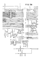
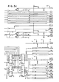
- Figs. 3A, 3B and 3C together form a schematic circuit diagram of the transmission control module of the system of Fig. 1; and
- Fig. 4 is a schematic circuit diagram of a power supply circuit for the circuit of Fig. 3.
- Referring now to the drawings, and initially to Fig. 1, there is illustrated an example of a vehicle control panel including gearshift levers and the like, and in connection with which a transmission controller in accordance with the invention may be advantageously utilized. The
transmission controller 10 of the invention is illustrated in block diagrammatic form in Fig. 2 in association with the transmission system of a relatively large vehicle, such as an agricultural tractor or the like, also illustrated somewhat diagrammatically. Certain of the control elements of Fig. 1 are also shown in Fig. 2 in operative association withcontroller 10. - Generally speaking, the transmission system as shown in Fig. 2 includes a plurality of gears (not shown) which are shifted by the controller in response to operation of a
gear shift lever 14. Also shown is a representataive clutch or "inching"pedal 16. clutches orclutch pedals 16. Therepresentative clutch pedal 16 is illustrated in Fig. 2, in connection with a safetydisconnect switch component 20 for detecting when the clutch is in a fully depressed condition. A clutchposition sensing arrangement 22 comprises a potentiometer for determining the relative position of the clutch pedal between a fully in, or disengaged, and a fully out or engaged position; that is, the "working range" of the clutch. - One or more valve-operated clutches are also provided in the vehicle with which the transmission controller of the invention is advantageously utilized. Accordingly, the control system also includes one or more corresponding solenoid operated valves, which are indicated diagrammatically in Fig. 1 by their associated
solenoid coils - The
gear shift 14 is preferably of the general type in which a shift pattern is reproduced electrically in the form of a cam-operated switching arrangement generally designated byreference numeral 30. Respective switching lines for forward, reverse, neutral-start and an up-and-down switch 31 carried onshift lever 14 form a digital logical representation which thetransmission controller 10 can readily interpret to determine the positions of a joystick-type control member in ashift pattern 33 of the gear shift mechanism and of theswitch 31. In the illustrated embodiment, there may be as many as ten possible variations or subcombinations of portions oflever 14 andswitch 31. Of course fewer or more such variations, or an alternate form of shift pattern or variation, might be utilized without departing from the invention. - Other elements of the transmission and related tractor systems and components illustrated in Fig. 2 include a
sensor 40 for developing an rpm signal corresponding to an engine speed (rpm) and a ground speed sensor, here diagrammatically illustrated as acoil 42. Thesensor 42 senses wheel axle speed and develops a corresponding signal, which will be understood to be an analog of the ground speed of the vehicle. - A throttle position sensor 46 is mechanically coupled with the
throttle 44 and preferably comprises a variable resistor or potentiometer for developing an electrical signal corresponding to the position of thethrottle 44. Finally, an auto downshift control member ordial 48 is provided for operator setting for a desired percentage of no-load engine speed at a given throttle position at which downshifting is to occur in accordance with the invention. The position of this dial orcontrol 48 is effectively sensed and converted to a corresponding signal by apotentiometer 50 which is mechanically coupled to thedial 48. - Details of the
transmission controller 10 are illustrated in Fig. 3, to which reference is next invited. It will be noted that in the diagram of Fig. 3, certain of the circuit configurations have been repeated in the figure, whereby those circuits identical in form with circuit configurations fully illustrated thereabove have been illustrated in block and labeled to indicate that the contents of these "blocks" are circuits identical with like-designated circuits illustrated thereabove. - A
display 60 gives information (preferably numeric) identifying the gear actually engaged, when thegear selector 14 is moved to the "forward"position 30. When thegear selector 14 is in the neutral position,display 60 identifies the gear that will be engaged by operation of the controller when the selector is moved to the forward position. - Referring briefly to Fig. 3C, a plurality of outputs are provided as indicated generally by
reference numeral 64. These include outputs for delivering a pulse width modulated (PWM) current to therespective solenoid coils reference numerals 66 and 68 (F1-PWM and F2-PWM). A number of spare outputs are indicated generally byreference numeral 70. - A plurality of additional inputs indicated generally at
reference numeral 72, also in Fig. 3C, include inputs for the respective forward (FOR), and reverse (REV), up (+) and down (-) sensors or switches associated withjoystick 14 and switch 31. Theclutch position sensor 22, and the clutch pedaldepressed sensor 20 are coupled atinputs Inputs downshift control sensor 50.Spare inputs - While a great number of control features can be and preferably are provided in connection with the illustrated transmission controller, the present invention is concerned primarily with the automatic downshifting feature mentioned hereinabove. Preferably, the controller of the invention will automatically downshift the transmission when the engine rpm falls below a predetermined percentage of the no-load rpm for a given throttle setting, which percentage is selectable at the auto
downshift control dial 48 by the operator. - Accordingly, and as best viewed in Fig. 3B, The
controller 10 includes a microcomputer ormicroprocessor 90, preferably of the type generally designated 8397. Themicrocomputer 90 has a plurality of input and output ports which are coupled with the inputs and outputs mentioned above by way of suitable intervening circuits. Themicrocomputer 90 may have suitable on-board memory, and additional outboard memory may be provided in the form ofmemory components - In accordance with the invention, the microcomputer or
microprocessor 90 comprises control means for the control of automatic gear selection means. The automatic gear selection means are operated by control signals produced at the outputs indicated generally atreference numeral 64 and referred to hereinabove. Accordingly the processor means is responsive to the throttle position signals produced by the throttle position sensing means and to rpm or engine speed signals produced by the engine sensor means for producing signals for controlling the selection of a lower gear in the event the sensed engine speed comprises less than a preselected percentage of a predetermined no-load engine speed at the sensed throttle position. That is, thetransmission controller 10 and, in particular, themicrocomputer 90 responds to the throttle position signals received from the potentiometer 46 and the engine rpm signals received from theengine speed sensor 40 for developing a gear selection control signal for selecting a different and lower gear should the engine rpm fall below the percentage of no-load rpm set by theauto downshift control 48; i.e., a predetermined and preprogrammed no-load value of engine rpm for the current throttle position. - While particular embodiments of the invention have been shown and described in detail, it will be obvious to those skilled in the art that changes and modifications of the present invention, in its various aspects, may be made without departing from the invention in its broader aspects, some of which changes and modifications being matters of routine engineering or design, and others being apparent only after study. As such, the scope of the invention should not be limited by the particular embodiment and specific construction described herein but should be defined by the appended claims and equivalents thereof. Accordingly, the aim in the appended claims is to cover all such changes and modifications as fall within the true spirit and scope of the invention.
Claims (5)
- A transmission controller for use with a vehicle having a transmission including a plurality of gears, said transmission controller comprising:
automatic gear selection control means for developing control signals for controlling automatic selection of one of said plurality of gears, throttle position sensing means for producing a throttle position signal corresponding to the position of a manually operated throttle of said vehicle, and engine sensor means for producing rpm signals corresponding to the engine speed of an engine of said vehicle, and wherein said automatic gear selection control means includes control signal producing means responsive to the throttle position signals and to the rpm signals for producing signals for controlling the selection of a lower gear in the event the sensed engine speed comprises less than a preselected percentage of a predetermined no-load engine speed at the sensed throttle position. - A transmission controller according to claim 1 and further including operator accessible selection means for selecting said preselected percentage, and for producing a corresponding signal to be transmitted to said automatic gear selection control means.
- A transmission controller for use with a vehicle having a transmission including a plurality of gears, said controller comprising: automatic gear selection control means for developing gear selection control signals to control the automatic selection of one of said plurality of gears; throttle position sensing means for producing a throttle position signal corresponding to the position of a throttle of said vehicle; and engine sensing means for producing rpm signals corresponding to the engine speed of an engine of said vehicle, wherein said automatic gear selection control means includes control signal producing means responsive to the throttle position signals and to the rpm signals for producing gear selection control signals for controlling the selection of a lower gear when the sensed rpm falls below a predetermined value relative to the sensed throttle position.
- A transmission controller according to claim 3 and further including operator accessible automatic downshift control means for developing a signal corresponding to a predetermined percentage of no-load engine speed and developing a predetermined percentage signal, and wherein said automatic gear selection control means is further responsive to said percentage signal for producing gear selection control signals for controlling the selection of a lower gear when the rpm signal is less than a percentage corresponding to the selected percentage signal of a predetermined no-load engine speed at the sensed throttle position.
- A transmission controller according to claim 3 and further including display means for displaying information identifying one of a gear actually engaged and a gear to be engaged in response to said automatic gear selection control means.
Applications Claiming Priority (2)
| Application Number | Priority Date | Filing Date | Title |
|---|---|---|---|
| US07/515,053 US5165307A (en) | 1990-04-26 | 1990-04-26 | Transmission controller |
| US515053 | 1990-04-26 |
Publications (1)
| Publication Number | Publication Date |
|---|---|
| EP0454041A1 true EP0454041A1 (en) | 1991-10-30 |
Family
ID=24049784
Family Applications (1)
| Application Number | Title | Priority Date | Filing Date |
|---|---|---|---|
| EP91106487A Ceased EP0454041A1 (en) | 1990-04-26 | 1991-04-23 | Transmission Control System |
Country Status (3)
| Country | Link |
|---|---|
| US (1) | US5165307A (en) |
| EP (1) | EP0454041A1 (en) |
| CA (1) | CA2041274A1 (en) |
Cited By (2)
| Publication number | Priority date | Publication date | Assignee | Title |
|---|---|---|---|---|
| CN1040574C (en) * | 1992-10-29 | 1998-11-04 | 易通公司 | Fault tolerant method of transmission gear selection |
| WO1999042746A1 (en) * | 1998-02-20 | 1999-08-26 | Zf Friedrichshafen Ag | Method for controlling an automatic transmission |
Families Citing this family (3)
| Publication number | Priority date | Publication date | Assignee | Title |
|---|---|---|---|---|
| DE19639200C1 (en) * | 1996-09-25 | 1997-12-18 | Daimler Benz Ag | Automatically controlled clutch in drive train of road vehicle |
| KR100748666B1 (en) * | 2005-12-09 | 2007-08-10 | 현대자동차주식회사 | Vehicle linear clutch system and control method |
| DE102013112968A1 (en) * | 2013-11-25 | 2015-05-28 | Dr. Ing. H.C. F. Porsche Ag | Method for controlling an internal combustion engine |
Citations (6)
| Publication number | Priority date | Publication date | Assignee | Title |
|---|---|---|---|---|
| EP0007881A1 (en) * | 1978-07-18 | 1980-02-06 | RENAULT VEHICULES INDUSTRIELS Société dite: | Method and device for assisting in driving a road vehicle |
| EP0097765A2 (en) * | 1982-06-24 | 1984-01-11 | Dr.Ing.h.c. F. Porsche Aktiengesellschaft | Control system for the propulsion unit of a motor vehicle |
| EP0128471A2 (en) * | 1983-06-01 | 1984-12-19 | Mazda Motor Corporation | Control means for vehicle automatic transmissions |
| EP0142046A1 (en) * | 1983-10-15 | 1985-05-22 | Nissan Motor Co., Ltd. | Method and apparatus for automatic transmisson cruise control |
| EP0109759B1 (en) * | 1982-11-17 | 1987-03-18 | Eaton Corporation | Automatic transmission controls |
| EP0269942A2 (en) * | 1984-07-23 | 1988-06-08 | Eaton Corporation | Semi-automatic mechanical transmission control |
Family Cites Families (9)
| Publication number | Priority date | Publication date | Assignee | Title |
|---|---|---|---|---|
| US4905544A (en) * | 1975-09-25 | 1990-03-06 | Ganoung David P | Powertrain control apparatus for improving fuel economy |
| JPS55109850A (en) * | 1979-02-14 | 1980-08-23 | Aisin Warner Ltd | Digital controller of automatic transmission gear |
| SE420295B (en) * | 1980-11-28 | 1981-09-28 | Saab Scania Ab | PROCEDURE FOR AUTOMATIC REPLACEMENT SELECTION IN A VEHICLE TRANSMISSION |
| JPS58214050A (en) * | 1982-06-04 | 1983-12-13 | Toyota Motor Corp | Indicating method for speed-change operation |
| KR900000592B1 (en) * | 1985-02-16 | 1990-02-01 | 미쓰비시지도오샤고오교오 가부시기가이샤 | Transmission control device of automatic transmission |
| JPS6229425A (en) * | 1985-07-30 | 1987-02-07 | Mazda Motor Corp | Gear shift timing indicating device for car |
| HU206654B (en) * | 1987-10-14 | 1992-12-28 | Csepeli Autogyar | Method for ratio switching of automatic or automatized mechanical synchronous gear box at motor vehicles |
| JPH0714703B2 (en) * | 1987-10-27 | 1995-02-22 | マツダ株式会社 | Vehicle constant speed control device |
| GB8728837D0 (en) * | 1987-12-10 | 1988-01-27 | Eaton Corp | Semi-automatic mechanical transmission control and control and control method |
-
1990
- 1990-04-26 US US07/515,053 patent/US5165307A/en not_active Expired - Fee Related
-
1991
- 1991-04-23 EP EP91106487A patent/EP0454041A1/en not_active Ceased
- 1991-04-25 CA CA002041274A patent/CA2041274A1/en not_active Abandoned
Patent Citations (6)
| Publication number | Priority date | Publication date | Assignee | Title |
|---|---|---|---|---|
| EP0007881A1 (en) * | 1978-07-18 | 1980-02-06 | RENAULT VEHICULES INDUSTRIELS Société dite: | Method and device for assisting in driving a road vehicle |
| EP0097765A2 (en) * | 1982-06-24 | 1984-01-11 | Dr.Ing.h.c. F. Porsche Aktiengesellschaft | Control system for the propulsion unit of a motor vehicle |
| EP0109759B1 (en) * | 1982-11-17 | 1987-03-18 | Eaton Corporation | Automatic transmission controls |
| EP0128471A2 (en) * | 1983-06-01 | 1984-12-19 | Mazda Motor Corporation | Control means for vehicle automatic transmissions |
| EP0142046A1 (en) * | 1983-10-15 | 1985-05-22 | Nissan Motor Co., Ltd. | Method and apparatus for automatic transmisson cruise control |
| EP0269942A2 (en) * | 1984-07-23 | 1988-06-08 | Eaton Corporation | Semi-automatic mechanical transmission control |
Cited By (2)
| Publication number | Priority date | Publication date | Assignee | Title |
|---|---|---|---|---|
| CN1040574C (en) * | 1992-10-29 | 1998-11-04 | 易通公司 | Fault tolerant method of transmission gear selection |
| WO1999042746A1 (en) * | 1998-02-20 | 1999-08-26 | Zf Friedrichshafen Ag | Method for controlling an automatic transmission |
Also Published As
| Publication number | Publication date |
|---|---|
| US5165307A (en) | 1992-11-24 |
| CA2041274A1 (en) | 1991-10-27 |
Similar Documents
| Publication | Publication Date | Title |
|---|---|---|
| US5089965A (en) | Shift prohibiting for automatic shift preselection mode for mechanical transmission system with semi-automatic shift implementation | |
| EP0352551B1 (en) | Upshift logic | |
| KR100338048B1 (en) | Method and device for controlling shifting | |
| KR100250507B1 (en) | Shift Execution Control Method and Device for Vehicle Mechanical Change Gear Transmission | |
| CA2047304C (en) | Amt cruise control mode shift logic | |
| EP0404353B1 (en) | Semi-automatic shift implementation for mechanical transmission system | |
| US5082097A (en) | Transmission controller | |
| US5249658A (en) | Transmission controller | |
| EP0404354A2 (en) | Control system and method for sensing and indicating neutral in a semi-automatic mechanical transmission system | |
| US5506771A (en) | Start gear ratio control system and method | |
| US6301537B1 (en) | Adaptive calibration of X-Y position sensor | |
| EP1103742A2 (en) | Driver-programmable driving mode system for automatic transmission | |
| JPH0659790B2 (en) | Automatic transmission device | |
| CA2248663C (en) | Transmission shift control system and method | |
| US5611245A (en) | Method and apparatus for controlling a power transmission to match vehicle ground speed | |
| EP0404352B1 (en) | Control system/method for controlling shifting of a range type compound transmission using input shaft and mainshaft speed sensors | |
| US6151543A (en) | Method and apparatus for skip shifting in a power transmission | |
| US5845224A (en) | Method and apparatus for preselecting gear ratios in a power transmission | |
| EP0769640B1 (en) | Skip shift selection control system and method | |
| US5022509A (en) | Semiautomatic shifter for a motor vehicle | |
| EP0431538B1 (en) | Manual override for automated mechanical transmission | |
| US5436833A (en) | Shift-to-neutral reminder prompt system/method | |
| US5165307A (en) | Transmission controller | |
| EP1456518B1 (en) | Drive unit for motor vehicle | |
| EP0576156B1 (en) | Enhanced semi-automated mechanical transmission system |
Legal Events
| Date | Code | Title | Description |
|---|---|---|---|
| PUAI | Public reference made under article 153(3) epc to a published international application that has entered the european phase |
Free format text: ORIGINAL CODE: 0009012 |
|
| AK | Designated contracting states |
Kind code of ref document: A1 Designated state(s): DE FR GB |
|
| 17P | Request for examination filed |
Effective date: 19920411 |
|
| 17Q | First examination report despatched |
Effective date: 19931025 |
|
| STAA | Information on the status of an ep patent application or granted ep patent |
Free format text: STATUS: THE APPLICATION HAS BEEN REFUSED |
|
| 18R | Application refused |
Effective date: 19950623 |