EP0454080B1 - Drahtloses Telefon mit der Fähigkeit zum schnellen Verbindungsaufbau während der Aufbauphase eines Anrufs - Google Patents
Drahtloses Telefon mit der Fähigkeit zum schnellen Verbindungsaufbau während der Aufbauphase eines Anrufs Download PDFInfo
- Publication number
- EP0454080B1 EP0454080B1 EP91106579A EP91106579A EP0454080B1 EP 0454080 B1 EP0454080 B1 EP 0454080B1 EP 91106579 A EP91106579 A EP 91106579A EP 91106579 A EP91106579 A EP 91106579A EP 0454080 B1 EP0454080 B1 EP 0454080B1
- Authority
- EP
- European Patent Office
- Prior art keywords
- channel
- cordless
- station
- channels
- signal
- Prior art date
- Legal status (The legal status is an assumption and is not a legal conclusion. Google has not performed a legal analysis and makes no representation as to the accuracy of the status listed.)
- Expired - Lifetime
Links
- 230000004044 response Effects 0.000 claims description 15
- 238000000034 method Methods 0.000 claims description 9
- 238000001228 spectrum Methods 0.000 description 3
- 230000005540 biological transmission Effects 0.000 description 2
- 238000004891 communication Methods 0.000 description 1
- 238000010586 diagram Methods 0.000 description 1
- 238000010295 mobile communication Methods 0.000 description 1
- 230000000737 periodic effect Effects 0.000 description 1
- 230000008054 signal transmission Effects 0.000 description 1
- 230000011664 signaling Effects 0.000 description 1
- 238000010408 sweeping Methods 0.000 description 1
Images


Classifications
-
- H—ELECTRICITY
- H04—ELECTRIC COMMUNICATION TECHNIQUE
- H04M—TELEPHONIC COMMUNICATION
- H04M1/00—Substation equipment, e.g. for use by subscribers
- H04M1/72—Mobile telephones; Cordless telephones, i.e. devices for establishing wireless links to base stations without route selection
- H04M1/725—Cordless telephones
- H04M1/72502—Cordless telephones with one base station connected to a single line
- H04M1/72505—Radio link set-up procedures
- H04M1/72508—Radio link set-up procedures using a control channel
-
- H—ELECTRICITY
- H04—ELECTRIC COMMUNICATION TECHNIQUE
- H04M—TELEPHONIC COMMUNICATION
- H04M1/00—Substation equipment, e.g. for use by subscribers
- H04M1/72—Mobile telephones; Cordless telephones, i.e. devices for establishing wireless links to base stations without route selection
- H04M1/725—Cordless telephones
- H04M1/72502—Cordless telephones with one base station connected to a single line
- H04M1/72505—Radio link set-up procedures
- H04M1/72511—Searching for available channels
-
- H—ELECTRICITY
- H04—ELECTRIC COMMUNICATION TECHNIQUE
- H04M—TELEPHONIC COMMUNICATION
- H04M1/00—Substation equipment, e.g. for use by subscribers
- H04M1/72—Mobile telephones; Cordless telephones, i.e. devices for establishing wireless links to base stations without route selection
- H04M1/725—Cordless telephones
- H04M1/733—Cordless telephones with a plurality of base stations connected to a plurality of lines
Definitions
- the present invention relates to a cordless telephone system.
- the system includes a base station interfacing the public or private switched telephone network and a cordless station for exchanging radio control signals with the base station to establish a connection.
- the base station constantly scans several speech channels to detect idle channels.
- the base station specifies one of the idle speech channels as a possible candidate and informs the cordless station of the identifier of the specified channel over the control channel and waits for a response from the cordless station until a prescribed period expires.
- the cordless station switches to the specified channel and checks for the availability of the specified channel.
- the base station Because of different field intensities between the sites of the base station and cordless station, the latter may determine that the specified channel is not actually available. Under such circumstances, the cordless station switches to the control channel and repeats the transmission of a call request to the base station. Failing to receive a response from the cordless station before the prescribed period expires, the base station recognizes that the specified channel is not available and switches to the control channel to wait for the retransmission of a call request. In response to the retransmission, the base station specifies another idle channel and informs this channel identifier to the cordless station to allow it to perform a channel check on the newly specified channel. The process will be repeated until an available speech channel is detected. Similar situations occur when an incoming call is received from the network.
- JP-A-1 208 919 discloses a radio communication system wherein a base station sends only one idle channel identifier and waits for the end-of-switching signal. If the latter is not received within a predetermined interval, the base station repeats the same process by scanning the channel spectrum to find a new idle channel and send its identifier.
- EP-A-0 189 920 and EP-A-0 213 929 also disclose a radio channel control method for mobile communication.
- the base station transmits a channel indicating signal to the cordless station over a control channel indicating that the detected idle channels can be used as possible candidate channels and switches to a first one of the candidate channels and waits for receipt of an end-of-switching signal from the cordless station during a prescribed period of time.
- the cordless station switches to the first candidate channel and tests the first candidate channel for availability and transmits an end-of-switching signal if the first candidate channel is determined as being idle.
- the base station switches to a second one of the candidate channels if the end-of-switching signal is not received from the cordless station during the prescribed period of time.
- the cordless station switches to the second candidate channel and tests the second candidate channel for availability if the first candidate channel is determined as being busy during the prescribed period of time and transmits the end-of-switching signal over the second candidate channel if it is determined as being idle.
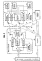
- Each cordless telephone system comprises a base station 2 connected to a public or private switched telephone network 1 through a subscriber loop 3, and a cordless station 4.
- Base station 2 1 includes a hybrid 10 having a two-wire circuit coupled through subscriber loop 3 1 to the network 1, the transmit portion of the four-wire circuit being coupled to the input of a radio transmitter 11 and the receive portion of the four-wire circuit being coupled to the output of a radio receiver 13.
- Transmitter 11 and receiver 13 are provided with a respective frequency synthesizer which is controlled by a control circuit 12.
- the output of transmitter 11 is connected to a transmit antenna 16 and the input of receiver 13 is connected to a receive antenna 17.
- a channel status memory 14 is connected to control circuit 12 to store busy/idle status of all speech channels. As will be described, this is done by sweeping the frequency synthesizer of receiver 13 across the allocated spectrum so that all speech channels are scanned at periodic intervals and detecting their field intensities.
- a carrier detector 15 is connected to receiver 13 to supply the control circuit 12 with a busy or idle status signal indicating that the detected carrier intensity of a switched channel is higher or lower than a prescribed threshold, respectively.
- the busy/idle conditions of all speech channels are stored into channel status memory 14 and periodically updated during a standby mode.
- the memory 14 is accessed by control circuit 12 to select idle speech channels to generate a channel indicating signal indicating that the detected idle channels can be used as possible candidate channels.
- radio signals from base station 21 are received by a receive antenna 28 and supplied to a radio receiver 20.
- Radio signals from base station 2 2 of adjacent system are also received by antenna 28 and fed into receiver 20.
- the audio-frequency output of receiver 20 is applied to a speech circuit 24 whose output is, in turn, coupled to the input of a radio transmitter 21.
- Speech circuit 24, which is normally turned off, is activated by control circuit 22 in response to a turn-on signal sent from base station 2 1 .
- the output of transmitter 21 is coupled to a transmit antenna 29 for transmission of signals to receive antenna 17 of the base station.
- Receiver 20 and transmitter 21 are provided with a respective frequency synthesizer which is controlled by a control circuit 22.
- a carrier detector 23 is coupled to receiver 20 to detect the intensity of transmitted carrier to supply control circuit 22 with information on the busy/idle status of a channel to which the station is being switched.
- a keypad 25 supplies dialing information as well as off-hook signal to control circuit 22.
- An idle channel memory 27 is connected to control circuit 22 to store idle channel data supplied from base station 2 1 to enable control circuit 22 to sequentially switch the station from one idle speech channel to the next until it detects an actually available speech channel. Receipt of a ringing signal sent from base station 2 1 causes control circuit 22 to activate a tone ringer 26 and the off-hook condition of the station or receipt of a turn-on signal for speech circuit causes control circuit 22 to deactivate it.
- the system has a single control channel and several speech channels. These control and speech channels are commonly used by adjacent systems, so radio signals from antenna 16 of base station 2 1 are also received by cordless station 4 2 as shown at A 1 and signals from base station 2 2 are also received by antenna 28 of station 4 1 as shown at A 2 . Likewise, signals from antenna 29 of station 4 1 are also received by base station 2 2 as shown at B 1 and signals from station 4 2 are also received by antenna 17 of base station 2 1 as shown at B 2 .
- control circuits 12 and 22 are a microprocessor-based controller which is programmed to perform a sequence of instructions as will be described hereinbelow.
- base-station control circuit 12 is shown to perform a standby routine in which it constantly scan all speech channels and examines their busy/idle status and updates the channel status memory 14.
- the program execution starts with step 31 in which variable i is set equal to 1.
- step 32 to cause base-station transmitter 11 and receiver 13 to switch to speech channel S i and proceeds to step 33 to check the carrier intensity of channel S i detected by carrier detector 15 against the prescribed threshold to determine if channel S i is idle or currently used by any cordless telephone system and store the busy/idle status of the channel into channel status memory 14.
- step 34 to increment variable i by one and moves ahead to decision step 35 to check to see if all speech channels are examined. If the answer is negative, control returns to step 32 to repeat the process on the next speech channel S i+1 until all speech channels are tested.
- step 35 If the answer is affirmative in step 35, control proceeds to step 36 to control the transmitter 11 and receiver 13 so that the base station is switched to the control channel to receive control signals (decision steps 37 and 38). If a call request is made from cordless station 4 1 , the decision in step 37 is affirmative and control exits to step 41 (Fig. 2B), and if there is an incoming call from the network, the decision in step 38 is affirmative and control exits to step 51 (Fig. 2C). If negative decision is made in both steps 37 and 38, control returns to step 31 to repeat the standby routine.
- base station 2 if there is an originating call from cordless station 4 1 , base station 2 returns an acknowledgment (ACK) signal over the control channel by containing in it a list of idle channels S i stored in memory 14 (step 41). Exit then is to step 42 to set variable i to 1 and switch the base station to an idle speech channel S i (step 43). A timeout period of T 1 seconds is then set in a timer (step 44), and the receipt of an end-of-switching signal from the cordless station is checked (step 45). If the end-of-switching signal is not received, control proceeds to step 46 to check to see if timeout period T 1 has expired.
- ACK acknowledgment
- step 46 If the answer is negative in step 46, control repeats steps 45 and 46 until timeout period T 1 expires. If an end-of-switching signal is received within the timeout period T 1 , control advances to step 49 to send a turn-on signal to the cordless station and enters a talking mode. Otherwise, it exits to step 47 to check to see if all channels contained in the idle channel list are tested. If the answer is negative, variable i is incremented by 1 (step 48) and control returns to step 43 to repeat the process so that the next idle speech channel S i+1 is examined. If no end-of-switching signal is received on each of the successively switched idle speech channels, the decision is affirmative in step 47 and control abandons the attempt to establish a connection and returns to the standby routine.
- step 51 if there is an incoming call from the network, base station 2 sends a channel assignment signal indicating a list of idle channels S i stored in memory 14 and the timer is set to period T 1 (step 51). Exit is to step 52 to check for receipt of an ACK signal from the cordless station. If the answer is negative in step 52, step 53 is executed to check for the expiration of period T 1 . If no ACK signal is returned within the period T 1 , control returns to step 51 to retransmit the channel assignment signal. If an ACK signal is received, control moves ahead to step 54 to set variable i to 1 and goes to a looped sequence of steps 55 through 60 which are respectively identical to steps 43 through 48 of Fig. 2B.
- control proceeds to step 61 to transmit a ringing signal over the switched speech channel to receive an off-hook signal (step 62) and transmit a turn-on signal (step 63) to enter a talking mode.
- step 71 checks to see if an off-hook condition has occurred. If the answer is affirmative, control exits to step 72 to switch the station to the control channel and checks the output of carrier detector 23 against the prescribed threshold to determine if the control channel is in use by another cordless telephone. If the answer is negative, control proceeds to step 73 to send a call request signal to base station 2. Exit then is to step 74 to check for the presence of a channel assignment signal. If there is none, control returns to step 73 to retransmit the call request signal, and if there is one, control proceeds to step 75 to store into idle channel memory 27 the list of idle speech channels contained in the transmitted channel assignment signal.
- Variable i is then set equal to 1 (step 76).
- the cordless station is then switched to an idle speech channel S i (step 77) and a timer is set to a timeout period T 1 (step 78).
- Exit is to step 79 to check the output of carrier detector 23 against the threshold to determine if that channel is busy. If it is, control exits to step 80 to check for the expiration of the timeout period and goes to step 81 to check to see if all channels of the idle list are tested. If the answer is negative, variable i is incremented by 1 (step 82) and control returns to step 77 to repeat the process on the next idle speech channel S i+1 . If the answer is affirmative in step 81, control returns to the starting point of the call originating routine.
- step 83 If the switched idle channel is not busy, exit then is to step 83 to send an end-of-switching signal, followed by the setting of the timer to a timeout period T 2 seconds in step 84. Exit then is to step 85 to check for the presence of a turn-on signal. If there is one, control proceeds to step 87 to turn on the speech circuit 24 to enter a talking mode. If the turn-on signal is not received, a timeout check is made (step 86) to repeat step 85 until period T 2 expires, whereupon control returns to step 71.
- the cordless station starts a call terminating routine with step 91 which checks for the presence of a channel assignment signal. If there is one, control proceeds to step 92 to store the list of idle speech channels contained in the received signal into memory 27 and goes to step 93 to return an ACK signal. Steps 94 through 100 are executed in a manner identical to steps 76 through 82 of Fig. 3A, so that idle channels will be successively tested if each test encounters a busy channel.
- step 97 If an idle speech channel is available, control exits from step 97 to step 101 to send an end-of-switching signal, causing the base station to send a ringing signal (step 61, Fig. 2C). If the ringing signal is received by the cordless station (step 102), the tone ringer 26 is activated (step 103) to urge the user to go off hook. If an off-hook condition is detected (step 104), control proceeds to step 105 to deactivate the tone ringer and goes to step 106 to send an off-hook signal, causing the base station to send a turn-on signal (step 63).
- the timer is set to period T 2 (step 107) to wait for the reception of the turn-on signal (step 108) until period T 2 expires (step 109). If the answer is affirmative in step 108, control exits to step 110 to turn on the speech circuit 24.
- a call request signal is sent (step 73, Fig. 3A) to base station 2 1 .
- base station 2 1 On receiving it (step 37, Fig. 2A), base station 2 1 returns an ACK signal containing a list of idle speech channels S 1 and S 2 (step 41, Fig. 2B).
- Data indicating the idle speech channels S 1 and S 2 are stored into idle channel memory 27 (step 75) and the cordless station is switched from the control channel to speech channel S 1 (steps 76, 77) and the busy/idle status of channel S 1 is checked during timeout period T 1 (steps 78, 79, 80).
- step 79 If channel S 1 is used by cordless station 4 2 , the signal from base unit 2 2 will be received by antenna 29 and carrier detector 23 produces an output. Therefore, the answer in step 79 is negative. After period T 1 expires, control exits from step 80 to step 81, and repeats the process so that cordless station 2 1 is then switched to speech channel S 2 .
- base station 2 1 Following transmission of the ACK signal, base station 2 1 is switched to idle channel S 1 (steps 42, 43, Fig. 2B) expecting the receipt of an end-of-switching on that channel from cordless station 4 1 . Since this signal is not received within the timeout period T 1 (step 46), base station 2 1 switches to channel S 2 . If this channel is detected by cordless station 4 1 as being idle, an end-of-switching signal is sent on channel S 2 (step 83, Fig. 3A). In response to this signal (step 45), base station 2 1 transmits a turn-on signal (step 49), which is received by the cordless station (step 85) to tum on the speech circuit 24.
- a channel assignment signal (step 51, Fig. 2C) containing in it the list of idle channels S 1 and S 2 .
- Cordless station 4 1 responds to this signal by returning an ACK signal (step 92, Fig. 3B) and switches to channel S 1 to check for its busy/idle status. If this channel is detected by cordless station 4 1 as being busy, period T 1 lapses and the cordless station switches to channel S 2 and transmits an end-of-switching signal on channel S 2 (step 101).
- Base station 2 1 responds to the ACK signal from cordless station 4 1 by switching to channel S 1 (steps 54, 55). Since this channel is found busy on the cordless station side of the system, period T 1 expires also in the base station (steps 58, 59) and it switches to channel S 2 (steps 60, 55) to receive the end-of-switching signal (step 57). A ringing signal is then sent to the cordless station (step 61).
- cordless station 4 1 When cordless station 4 1 activates its tone ringer (steps 102, 103) in response to the ringing signal, goes off hook (step 104) and deactivates the tone ringer (step 105), an off-hook signal is then sent (step 106), which is received by the base station (step 62) and a turn-on signal is sent to the cordless station (step 63) to allow it turn on its speech circuit.
- the base station is switched successively to the same channel in response to the end-of-switching signal from the cordless station signaling that the switched speech channel is also idle on the cordless station side of the system.
Landscapes
- Engineering & Computer Science (AREA)
- Computer Networks & Wireless Communication (AREA)
- Signal Processing (AREA)
- Mobile Radio Communication Systems (AREA)
Claims (8)
- Drahtlos-Telefonsystem mit einem Steuerkanal und mehreren Sprachkanälen, das eine mit einem Telefonwählnetz (1) verbundene Basisstation (2) und einen drahtlosen Telefonapparat (4) aufweist,dadurch gekennzeichnet, daßwobei die Basisstation (2) aufweist: Einrichtungen (11-13, 31-35) zum Abtasten der Sprachkanäle während einem Stand-by-Modus, um einen freien Kanal aus den abgetasteten Kanälen zu ermitteln, und Einrichtungen, die auf eine Verbindungsanforderung von dem drahtlosen Telefonapparat (4) oder einen ankommenden Ruf vom Netz antworten, um über den Steuerkanal ein Kanalanzeigesignal an den drahtlosen Telefonapparat zu senden, welches anzeigt, daß die ermittelten freien Kanäle als mögliche Kanalkandidaten verwendet werden können, und um auf ein Vermittlungsendesignal von dem drahtlosen Telefonapparat (4) zu warten, undwobei der drahtlose Telefonapparat (4) aufweist: Einrichtungen (20, 22, 72, 91) zum Empfangen des Kanalanzeigesignals über den Steuerkanal und Einrichtungen (21, 22) zum Auswählen des durch das Kanalanzeigesignal identifizierten Sprachkanals und zum Senden des Vermittlungsendesignals an die Basisstation (2), wenn der ausgewählte Sprachkanal an dem Standort des drahtlosen Telefonapparats verfügbar ist,die Basisstation (2) ferner aufweist: Einrichtungen (41, 51) zum Übertragen des Kanalanzeigesignals, das eine Liste aus mehr als einem freien Kanal als mögliche Kanalkandidaten enthält, und Einrichtungen (42-48, 54-60) zum Auswählen eines der Kanalkandidaten vor dem Warten auf das Vermittlungsendesignal und zum Auswählen eines anderen Kandidaten, wenn das Vermittlungsendesignal nicht innerhalb einer vorgeschriebenen Zeitspanne empfangen wird, undder drahtlose Telefonapparat (4) ferner aufweist: Einrichtungen (21, 22, 76-82, 94-100), um nach Empfang des Kanalanzeigesignals einen der Kanalkandidaten auszuwählen, die durch das Kanalanzeigesignal angezeigt werden, welcher dem von der Basisstation (2) ausgewählten Kanal entspricht, um den ausgewählten Kanal auf Verfügbarkeit zu prüfen und um das Vermittlungsendesignal über den ausgewählten Kanalkandidaten zu senden, wenn der letztere verfügbar ist, und um einen anderen Kanalkandidaten auszuwählen und auf Verfügbarkeit zu prüfen, wenn der zuerst ausgewählte Kanal nicht verfügbar ist, und um das Vermittlungsendesignal über den als zweites ausgewählten Kanalkandidaten zu senden, wenn der letztere verfügbar ist.
- Drahtlos-Telefonsystem nach Anspruch 1, wobei die Basisstation aufweist: Einrichtungen (42-48, 54-60), um während einer zweiten vorgeschriebenen Zeitspanne, nachdem die Basisstation auf den zweiten Kanalkandidaten geschaltet ist, auf den Empfang des Vermittlungsendesignals zu warten, und um einen dritten der freien Kanäle auszuwählen, wenn das Vermittlungsendesignal während der zweiten vorgeschriebenen Zeitspanne nicht empfangen wird, und wobei der drahtlose Telefonapparat aufweist: Einrichtungen (76-82, 94-100) zum Auswählen und Prüfen des dritten Kanalkandidaten, wenn der zweite ausgewählte Kanalkandidat während der zweiten vorgeschriebenen Zeitspanne als belegt bestimmt wird, und zum Senden des Vermittlungsendesignals über den dritten ausgewählten Kanal, wenn derselbe als frei bestimmt wird.
- Drahtlos-Telefonsystem nach Anspruch 1 oder 2, wobei die Basisstation eine Speichereinrichtung (14) zum Speichern des Belegt-/Freizustands der abgetasteten Kanäle und Einrichtungen (12) zum periodischen Aktualisieren des Belegt-/Freizustands der abgetasteten Kanäle während des Stand-by-Modus aufweist.
- Drahtlos-Telefonsystem nach Anspruch 1, 2 oder 3, wobei der drahtlose Telefonapparat (4) aufweist: eine Speichereinrichtung (27) zum Speichern von Daten, welche die möglichen Kanalkandidaten anzeigen, die in dem empfangenen Kanalanzeigesignal enthalten sind, und Auswählen eines der Kanalkandidaten gemäß den in der genannten Speichereinrichtung (27) gespeicherten Daten.
- Drahtlos-Telefonsystem nach einem der Ansprüche 1 bis 4, wobei die Basisstation aufweist: eine Einrichtung (49), um ansprechend auf den Empfang des Vermittlungsendesignals ein Sprechfreigabesignal an den drahtlosen Telefonapparat zu senden, wenn die Verbindungsanforderung von dem drahtlosen Telefonapparat erzeugt wird, und wobei der drahtlose Telefonapparat eine Einrichtung (85) aufweist, um ansprechend auf das Sprechfreigabesignal eine Sprechverbindung aufzubauen.
- Drahtlos-Telefonsystem nach einem der Ansprüche 1 bis 5, wobei die Basisstation aufweist: eine Einrichtung (61), um ansprechend auf den Empfang des Vermittlungsendesignals ein Läutsignal an den drahtlosen Telefonapparat zu senden, wenn der ankommende Ruf vom Netz empfangen wird, und Einrichtungen (62, 63), um ansprechend auf den Empfang eines Abnehmesignals von dem drahtlosen Telefonapparat ein Sprechfreigabesignal an den drahtlosen Telefonapparat zu senden, und wobei der drahtlose Telefonapparat aufweist: eine Rufklingel (26, 102, 103), um Benutzer ansprechend auf den Empfang des Klingelsignals zu alarmieren, Einrichtungen (104, 106), um das Abnehmesignal zu senden, wenn an dem drahtlosen Telefonapparat ein Abnehmezustand ermittelt wird, Einrichtungen (108-110), um ansprechend auf das Sprechfreigabesignal eine Sprechverbindung aufzubauen.
- Verfahren in einem Drahtlos-Telefonsystem mit einem Steuerkanal und mehreren Sprachkanälen, das die folgenden Schritte aufweist:a) Abtasten der Sprachkanäle während eines Stand-by-Modus, um freie Kanäle aus den abgetasteten Kanälen zu ermitteln;b) Empfangen einer Verbindungsanforderung von einem drahtlosen Telefonapparat (4) an einer Basisstation (2) oder eines ankommenden Rufs von einem Telefonwählnetz an dieser Basisstation;c) Senden eines Kanalanzeigesignals von der Basisstation über den Steuerkanal an den drahtlosen Telefonapparat, welches anzeigt, daß die ermittelten freien Kanäle als mögliche Kanalkandidaten verwendet werden können, und Empfangen des Kanalanzeigesignals über den Steuerkanal an dem drahtlosen Telefonapparat;d) Schalten der Basisstation auf einen ersten der Kanalkandidaten und Warten auf den Empfang eines Vermittlungsendesignals von dem drahtlosen Telefonapparat während einer vorgeschriebenen Zeitspanne und Schalten des drahtlosen Telefonapparats auf den ersten Kanalkandidaten und Prüfen des ersten Kanalkandidaten auf Verfügbarkeit an dem Standort des drahtlosen Telefonapparats und Senden eines Vermittlungsendesignals, wenn der erste Kanalkandidat als frei bestimmt wird; unde) Schalten der Basisstation auf einen zweiten der Kanalkandidaten, wenn das Vermittlungsendesignal von dem drahtlosen Telefonapparat während der vorgeschriebenen Zeitspanne nicht empfangen wird, und Schalten des drahtlosen Telefonapparats auf den zweiten Kanalkandidaten und Prüfen des zweiten Kanalkandidaten auf Verfügbarkeit an dem Standort des drahtlosen Telefonapparats, wenn der erste Kanalkandidat während der vorgeschriebenen Zeitspanne als belegt bestimmt wird, und Senden des Vermittlungsendesignals über den zweiten Kanalkandidaten, wenn derselbe als frei bestimmt wird.
- Verfahren nach Anspruch 7, das ferner die folgenden Schritte aufweist:A) Warten auf den Empfang des Vermittlungsendesignals während einer zweiten vorgeschriebenen Zeitspanne, nachdem die Basisstation auf den zweiten Kanalkandidaten geschaltet ist;B) Schalten der Basisstation auf einen dritten der freien Kanäle, wenn das Vermittlungsendesignal während der zweiten vorgeschriebenen Zeitspanne nicht empfangen wird, Schalten des drahtlosen Telefonapparats auf den dritten Kanalkandidaten, wenn der zweite Kanalkandidat während der zweiten vorgeschriebenen Zeitspanne als belegt bestimmt wird, und Prüfen des dritten Kanalkandidaten auf Verfügbarkeit an dem Standort des drahtlosen Telefonapparats; undC) Senden des Vermittlungsendesignals von dem drahtlosen Telefonapparat über den dritten ausgewählten Kanal, wenn derselbe als frei bestimmt wird.
Applications Claiming Priority (2)
| Application Number | Priority Date | Filing Date | Title |
|---|---|---|---|
| JP2108351A JP2595758B2 (ja) | 1990-04-24 | 1990-04-24 | コードレス電話方式 |
| JP108351/90 | 1990-04-24 |
Publications (3)
| Publication Number | Publication Date |
|---|---|
| EP0454080A2 EP0454080A2 (de) | 1991-10-30 |
| EP0454080A3 EP0454080A3 (en) | 1993-04-14 |
| EP0454080B1 true EP0454080B1 (de) | 1998-01-14 |
Family
ID=14482510
Family Applications (1)
| Application Number | Title | Priority Date | Filing Date |
|---|---|---|---|
| EP91106579A Expired - Lifetime EP0454080B1 (de) | 1990-04-24 | 1991-04-24 | Drahtloses Telefon mit der Fähigkeit zum schnellen Verbindungsaufbau während der Aufbauphase eines Anrufs |
Country Status (7)
| Country | Link |
|---|---|
| US (1) | US5384827A (de) |
| EP (1) | EP0454080B1 (de) |
| JP (1) | JP2595758B2 (de) |
| KR (1) | KR950013161B1 (de) |
| AU (1) | AU636476B2 (de) |
| CA (1) | CA2041030C (de) |
| DE (1) | DE69128658T2 (de) |
Families Citing this family (16)
| Publication number | Priority date | Publication date | Assignee | Title |
|---|---|---|---|---|
| JPH04293325A (ja) * | 1991-03-22 | 1992-10-16 | Nec Corp | 無線電話装置 |
| US5260988A (en) * | 1992-02-06 | 1993-11-09 | Motorola, Inc. | Apparatus and method for alternative radiotelephone system selection |
| AU2595595A (en) * | 1994-05-19 | 1995-12-18 | Airnet Communications Corporation | System for dynamically allocating channels among base stations in a wireless communication system |
| US5870678A (en) * | 1994-12-22 | 1999-02-09 | Matsushita Electric Industrial Co., Ltd. | Cordless telephone apparatus |
| CN1089972C (zh) * | 1995-01-25 | 2002-08-28 | Ntt移动通信网株式会社 | 移动通信系统 |
| JPH09130853A (ja) * | 1995-10-26 | 1997-05-16 | Uniden Corp | 通信方法,通信装置及びコードレス電話装置 |
| EP0786917B1 (de) * | 1996-01-23 | 2013-08-21 | Ntt Mobile Communications Network Inc. | Mobiles Kommunikationssystem, Netzwerk und Mobilstation |
| US6160805A (en) * | 1996-09-30 | 2000-12-12 | Motorola, Inc. | Method for synchronizing a session timer |
| JPH10164660A (ja) * | 1996-11-29 | 1998-06-19 | Nec Corp | 無線通信装置 |
| JP2000504532A (ja) * | 1996-11-29 | 2000-04-11 | コーニンクレッカ フィリップス エレクトロニクス エヌ ヴィ | 電気通信システム、チャネル選択プロトコル及び無線局 |
| US6212396B1 (en) * | 1997-03-27 | 2001-04-03 | Nortel Networks Limited | Generic handset programming and configuration |
| US6078821A (en) * | 1998-02-25 | 2000-06-20 | Motorola, Inc. | Cordless radiotelephone system having an extendable geographic coverage area and method therefor |
| US7251488B2 (en) * | 2002-06-28 | 2007-07-31 | Interdigital Technology Corporation | Method and system for coordinating services in integrated WLAN-cellular systems |
| JP4207005B2 (ja) * | 2005-01-28 | 2009-01-14 | ブラザー工業株式会社 | コードレス装置 |
| WO2007100032A1 (ja) * | 2006-03-01 | 2007-09-07 | Nec Corporation | 移動通信システム、そのスクランブルコード割り当て方法、移動局、および基地局 |
| CN108809545B (zh) * | 2017-05-04 | 2023-01-06 | 华为技术有限公司 | 传输上行控制信息的方法和装置 |
Family Cites Families (14)
| Publication number | Priority date | Publication date | Assignee | Title |
|---|---|---|---|---|
| JPS5930333A (ja) * | 1982-08-13 | 1984-02-17 | Nippon Telegr & Teleph Corp <Ntt> | 無線回線設定方法 |
| JPS61177040A (ja) * | 1985-01-31 | 1986-08-08 | Nec Corp | 無線回線制御方式 |
| JPH0352048Y2 (de) * | 1985-04-30 | 1991-11-11 | ||
| JPS61274531A (ja) * | 1985-05-30 | 1986-12-04 | Nec Corp | チヤネル選択方式 |
| US4802200A (en) * | 1985-08-27 | 1989-01-31 | Nippon Telegraph And Telephone Corporation | Radio telephone system control apparatus and method |
| US4672657A (en) * | 1985-12-17 | 1987-06-09 | Motorola, Inc. | Multichannel telephone system |
| GB8531492D0 (en) * | 1985-12-20 | 1986-02-05 | Racal Res Ltd | Cordless telephones |
| JP2580129B2 (ja) * | 1986-07-18 | 1997-02-12 | ソニー株式会社 | 送受信装置 |
| JPS6348926A (ja) * | 1986-08-19 | 1988-03-01 | Fujitsu Ltd | コ−ドレステレホンのマルチチヤネルアクセス方式 |
| DE3643004A1 (de) * | 1986-12-17 | 1988-06-30 | Philips Patentverwaltung | Verfahren und schaltungsanordnung zum verbindungsaufbau und ueberwachung bei einem schnurlosen telefonapparat |
| FI97010C (fi) * | 1987-05-29 | 1996-09-25 | Nec Corp | Ohjausasema ja radiotiedonsiirtoverkkojärjestelmä, joka sisältää eri toimintatiloissa toimivia kytkentälaiteyksiköitä |
| JP2642380B2 (ja) * | 1988-02-16 | 1997-08-20 | 日本電信電話株式会社 | 無線通信装置 |
| JPH02228137A (ja) * | 1989-03-01 | 1990-09-11 | Mitsubishi Electric Corp | 無線回線設定方法 |
| JPH02249326A (ja) * | 1989-03-23 | 1990-10-05 | Iwatsu Electric Co Ltd | 空きチャンネル指定方式 |
-
1990
- 1990-04-24 JP JP2108351A patent/JP2595758B2/ja not_active Expired - Lifetime
-
1991
- 1991-04-23 KR KR1019910006495A patent/KR950013161B1/ko not_active Expired - Fee Related
- 1991-04-23 CA CA002041030A patent/CA2041030C/en not_active Expired - Fee Related
- 1991-04-23 AU AU75308/91A patent/AU636476B2/en not_active Ceased
- 1991-04-24 US US07/690,417 patent/US5384827A/en not_active Expired - Lifetime
- 1991-04-24 EP EP91106579A patent/EP0454080B1/de not_active Expired - Lifetime
- 1991-04-24 DE DE69128658T patent/DE69128658T2/de not_active Expired - Fee Related
Also Published As
| Publication number | Publication date |
|---|---|
| HK1002543A1 (en) | 1998-08-28 |
| JP2595758B2 (ja) | 1997-04-02 |
| KR910019469A (ko) | 1991-11-30 |
| EP0454080A3 (en) | 1993-04-14 |
| EP0454080A2 (de) | 1991-10-30 |
| AU636476B2 (en) | 1993-04-29 |
| US5384827A (en) | 1995-01-24 |
| CA2041030C (en) | 1995-02-07 |
| DE69128658D1 (de) | 1998-02-19 |
| JPH046919A (ja) | 1992-01-10 |
| AU7530891A (en) | 1991-11-07 |
| DE69128658T2 (de) | 1998-05-14 |
| KR950013161B1 (ko) | 1995-10-25 |
Similar Documents
| Publication | Publication Date | Title |
|---|---|---|
| EP0454080B1 (de) | Drahtloses Telefon mit der Fähigkeit zum schnellen Verbindungsaufbau während der Aufbauphase eines Anrufs | |
| EP0189920B1 (de) | Funkkanalsteuerungsverfahren für ein mobiles Kommunikationssystem | |
| EP0441370B1 (de) | Schnurloses Telefonsystem im Grossraum, geeignet zum Empfang ankommender Anrufe mit einer Gruppenadresse | |
| AU636736B2 (en) | Cordless key telephone system capable of quickly answering incoming calls | |
| EP0243900B1 (de) | Funktelefonsystem mit gemeinsamem Signalisierungskanal | |
| EP0452872B1 (de) | Schnurlose Reihenanlage zur Abdeckung mehrerer Bedienungszonen mit exklusiver Zuteilung der Steuerkanäle | |
| US5454028A (en) | Cordless key telephone system having zone switching function | |
| EP0631417B1 (de) | Verfahren und Steuereinrichtung für ein Funktelefonsystem | |
| US4228319A (en) | Automatic radio telephone system | |
| EP0214809B1 (de) | Gerät und Verfahren zur Kontrolle eines Funktelefonsystems | |
| CA1266932A (en) | Cordless telephone system | |
| WO1993016549A1 (en) | Call routing for a radiotelephone in multiple radiotelephone systems | |
| JPS63164721A (ja) | コードレス電話機における接続形成、接続監視方法 | |
| EP0218450B2 (de) | Kontrollsystem für einen Radiofernsprecher | |
| EP0335742A2 (de) | Mobiles Kommunikationssystem und dessen Steuerungsverfahren | |
| EP0882348B1 (de) | Ein telekommunikationssystem, ein kanalauswahlprotokoll und eine funkstation | |
| EP0363492B1 (de) | Funkübertragungssystem und entsprechendes regelungsverfahren | |
| JP3582200B2 (ja) | 無線装置 | |
| HK1002543B (en) | Cordless telephone system capable of quickly establishing connection during call setup phase | |
| KR920009152B1 (ko) | 구내 무선전화 시스템 | |
| KR0137353B1 (ko) | 주파수 공용시스템의 통화채널 접속방법 | |
| KR960004811B1 (ko) | 구내 무선전화 시스템 및 그 채널 스캔 방법 | |
| KR0135963B1 (ko) | 구내 무선전화 시스템의 휴대장치 제어방법 | |
| KR930011472A (ko) | 구내 무선전화 시스템 | |
| JPS62189829A (ja) | 移動無線通信のマルチチヤンネルアクセス方式 |
Legal Events
| Date | Code | Title | Description |
|---|---|---|---|
| PUAI | Public reference made under article 153(3) epc to a published international application that has entered the european phase |
Free format text: ORIGINAL CODE: 0009012 |
|
| 17P | Request for examination filed |
Effective date: 19910521 |
|
| AK | Designated contracting states |
Kind code of ref document: A2 Designated state(s): DE GB SE |
|
| PUAL | Search report despatched |
Free format text: ORIGINAL CODE: 0009013 |
|
| AK | Designated contracting states |
Kind code of ref document: A3 Designated state(s): DE GB SE |
|
| 17Q | First examination report despatched |
Effective date: 19960130 |
|
| GRAG | Despatch of communication of intention to grant |
Free format text: ORIGINAL CODE: EPIDOS AGRA |
|
| GRAG | Despatch of communication of intention to grant |
Free format text: ORIGINAL CODE: EPIDOS AGRA |
|
| GRAG | Despatch of communication of intention to grant |
Free format text: ORIGINAL CODE: EPIDOS AGRA |
|
| GRAH | Despatch of communication of intention to grant a patent |
Free format text: ORIGINAL CODE: EPIDOS IGRA |
|
| GRAH | Despatch of communication of intention to grant a patent |
Free format text: ORIGINAL CODE: EPIDOS IGRA |
|
| GRAA | (expected) grant |
Free format text: ORIGINAL CODE: 0009210 |
|
| AK | Designated contracting states |
Kind code of ref document: B1 Designated state(s): DE GB SE |
|
| REF | Corresponds to: |
Ref document number: 69128658 Country of ref document: DE Date of ref document: 19980219 |
|
| PLBE | No opposition filed within time limit |
Free format text: ORIGINAL CODE: 0009261 |
|
| STAA | Information on the status of an ep patent application or granted ep patent |
Free format text: STATUS: NO OPPOSITION FILED WITHIN TIME LIMIT |
|
| 26N | No opposition filed | ||
| PGFP | Annual fee paid to national office [announced via postgrant information from national office to epo] |
Ref country code: SE Payment date: 20010409 Year of fee payment: 11 |
|
| PGFP | Annual fee paid to national office [announced via postgrant information from national office to epo] |
Ref country code: DE Payment date: 20010418 Year of fee payment: 11 |
|
| REG | Reference to a national code |
Ref country code: GB Ref legal event code: IF02 |
|
| PG25 | Lapsed in a contracting state [announced via postgrant information from national office to epo] |
Ref country code: SE Free format text: LAPSE BECAUSE OF NON-PAYMENT OF DUE FEES Effective date: 20020425 |
|
| PG25 | Lapsed in a contracting state [announced via postgrant information from national office to epo] |
Ref country code: DE Free format text: LAPSE BECAUSE OF NON-PAYMENT OF DUE FEES Effective date: 20021101 |
|
| EUG | Se: european patent has lapsed |
Ref document number: 91106579.5 |
|
| PGFP | Annual fee paid to national office [announced via postgrant information from national office to epo] |
Ref country code: GB Payment date: 20090422 Year of fee payment: 19 |
|
| GBPC | Gb: european patent ceased through non-payment of renewal fee |
Effective date: 20100424 |
|
| PG25 | Lapsed in a contracting state [announced via postgrant information from national office to epo] |
Ref country code: GB Free format text: LAPSE BECAUSE OF NON-PAYMENT OF DUE FEES Effective date: 20100424 |