EP0454315A2 - Plateau d'analyse - Google Patents
Plateau d'analyse Download PDFInfo
- Publication number
- EP0454315A2 EP0454315A2 EP91303083A EP91303083A EP0454315A2 EP 0454315 A2 EP0454315 A2 EP 0454315A2 EP 91303083 A EP91303083 A EP 91303083A EP 91303083 A EP91303083 A EP 91303083A EP 0454315 A2 EP0454315 A2 EP 0454315A2
- Authority
- EP
- European Patent Office
- Prior art keywords
- chamber
- tray
- assembly
- tubular
- wells
- Prior art date
- Legal status (The legal status is an assumption and is not a legal conclusion. Google has not performed a legal analysis and makes no representation as to the accuracy of the status listed.)
- Granted
Links
Images
Classifications
-
- B—PERFORMING OPERATIONS; TRANSPORTING
- B01—PHYSICAL OR CHEMICAL PROCESSES OR APPARATUS IN GENERAL
- B01L—CHEMICAL OR PHYSICAL LABORATORY APPARATUS FOR GENERAL USE
- B01L3/00—Containers or dishes for laboratory use, e.g. laboratory glassware; Droppers
- B01L3/50—Containers for the purpose of retaining a material to be analysed, e.g. test tubes
- B01L3/502—Containers for the purpose of retaining a material to be analysed, e.g. test tubes with fluid transport, e.g. in multi-compartment structures
- B01L3/5025—Containers for the purpose of retaining a material to be analysed, e.g. test tubes with fluid transport, e.g. in multi-compartment structures for parallel transport of multiple samples
- B01L3/50255—Multi-well filtration
-
- G—PHYSICS
- G01—MEASURING; TESTING
- G01N—INVESTIGATING OR ANALYSING MATERIALS BY DETERMINING THEIR CHEMICAL OR PHYSICAL PROPERTIES
- G01N33/00—Investigating or analysing materials by specific methods not covered by groups G01N1/00 - G01N31/00
- G01N33/48—Biological material, e.g. blood, urine; Haemocytometers
- G01N33/50—Chemical analysis of biological material, e.g. blood, urine; Testing involving biospecific ligand binding methods; Immunological testing
- G01N33/53—Immunoassay; Biospecific binding assay; Materials therefor
- G01N33/5302—Apparatus specially adapted for immunological test procedures
-
- G—PHYSICS
- G01—MEASURING; TESTING
- G01N—INVESTIGATING OR ANALYSING MATERIALS BY DETERMINING THEIR CHEMICAL OR PHYSICAL PROPERTIES
- G01N30/00—Investigating or analysing materials by separation into components using adsorption, absorption or similar phenomena or using ion-exchange, e.g. chromatography or field flow fractionation
- G01N30/02—Column chromatography
- G01N30/26—Conditioning of the fluid carrier; Flow patterns
- G01N30/38—Flow patterns
- G01N30/46—Flow patterns using more than one column
- G01N30/466—Flow patterns using more than one column with separation columns in parallel
-
- G—PHYSICS
- G01—MEASURING; TESTING
- G01N—INVESTIGATING OR ANALYSING MATERIALS BY DETERMINING THEIR CHEMICAL OR PHYSICAL PROPERTIES
- G01N30/00—Investigating or analysing materials by separation into components using adsorption, absorption or similar phenomena or using ion-exchange, e.g. chromatography or field flow fractionation
- G01N30/02—Column chromatography
- G01N30/60—Construction of the column
- G01N30/6034—Construction of the column joining multiple columns
- G01N30/6043—Construction of the column joining multiple columns in parallel
-
- G—PHYSICS
- G01—MEASURING; TESTING
- G01N—INVESTIGATING OR ANALYSING MATERIALS BY DETERMINING THEIR CHEMICAL OR PHYSICAL PROPERTIES
- G01N30/00—Investigating or analysing materials by separation into components using adsorption, absorption or similar phenomena or using ion-exchange, e.g. chromatography or field flow fractionation
- G01N30/02—Column chromatography
- G01N30/60—Construction of the column
- G01N30/6047—Construction of the column with supporting means; Holders
Definitions
- the present invention relates to an assay tray assembly. It is particularly concerned with an assembly for use in the testing or analysis of liquids, usually of a chemical, bio-chemical or biological nature, by a batch process whereby multiple small quantities of the liquid or liquids under test can be prepared for analysis substantially simultaneously, the process conveniently being carried out by conventional mechanical handling equipment.
- Assemblies of the kind mentioned include an separation medium to which the liquid for analysis is subjected; this medium may simply serve to remove solid/particulate matter from the liquid by filtration or may be in the form of chromatographic medium having a selectively adsorbent nature intended to separate or indicate a particular characteristic (or the lack of such a characteristic) of the liquid under test.
- a conventional assay technique is to locate the separation medium in an upstanding tubular chamber having an open top and a bottom outlet and to pipette or otherwise deposit the liquid under test into the chamber to flow through or over the extraction medium prior to emerging from the bottom outlet.
- this type of analysis is made on an individual basis,for example by use of an extraction cartridge sold under the Trade Mark BOND ELUT which comprises a tubular plastics body carried within which is a predetermined chromatographic medium.
- Such individual cartridges have been found inappropriate in trying to achieve a high through put of test samples for analysis. It has however been proposed, in U.S. Patent No.
- an assay tray assembly comprising a plastics moulded test tray removably mounted in overlying relationship in engagement with a plastics moulded collection tray; the test tray having a spaced array of discrete identical upstanding chambers to accommodate a predetermined volume of liquid for analysis, each chamber being formed with a top opening and a bottom opening for the flow therethrough of the liquid, said bottom opening being located in a downwardly projecting tubular spigot for the respective chamber and each said chamber carrying a separation medium to which the liquid is to be subjected during its said through-flow; the collection tray having discrete upstanding wells each with an upwardly opening mouth, said wells corresponding in number to the chambers and having their mouths disposed in a spaced array corresponding to that of the tubular spigots; the tubular spigots being received one in each of said well mouths for the respective wells to collect liquid emanating from the chambers and to alleviate cross contamination between such liquids and wherein abutment means is provided between the test tray
- the tubular spigots of the chambers are received, or intended to be received, one each in the mouths of discrete wells in a collection tray. This ensures that the liquid (or liquids) which is under test will flow over or through the separation medium and by way of the opening in the bottom of its respective chamber into a particular well of the collection chamber without unintentional seepage or cross contamination of such liquid between the adjacent chambers or wells. Furthermore, in the assembly of the invention it is intended that the volume of each well is capable of accommodating below the tubular spigot with which it communicates, all of the liquid (the percolate or eluate) which passes through the tubular spigot and is derived from the liquid initially deposited in the corresponding chamber.
- the liquid under test will usually be pipetted into the chambers in predetermined volumes, possibly to the extent that a particular chamber is full of such liquid above the separation medium and the volume of the well should be capable of accommodating an equivalent volume of liquid below and out of contact with the tubular spigot.
- the trays are preferably formed as one piece injection mouldings with their respective chambers and wells disposed in a conventional microtiter plate layout, that is arrayed in columns and rows extending perpendicularly thereto.
- a typical such array has twelve parallel columns and eight parallel rows to provide ninety six chambers or wells in the respective trays (this latter array is likely to prove most acceptable for automatic handling of the trays by multiple batch pipetting equipment which is currently available).
- the trays will usually have moulded-in indicia for individually identifying each chamber or well as the case may be and similar indicia will normally be provided for both the test tray and the collection tray.
- Orientating means may be provided which permits engagement between the two trays only when they are mounted in their correct overlying relationship in which it is ensured that the two trays are correctly orientated with respect to each other (that is when the individually identified tubular spigots engage within correspondingly individually identified wells).
- the orientating means can conveniently comprise moulded-in tracks, projections, recesses or rebates on the trays which are intended to inter-engage between the trays when the trays are correctly mounted (or possibly to engage with mechnical handling equipment to ensure that the test and collection trays are correctly orientated with respect to each other and in the equipment) prior to the chambers being charged with the liquid under test.
- the chambers are preferably formed by downwardly extending tubes in a substantially parallel array which tubes may be maintained in their spaced array by upstanding webs of the test tray that interconnect each such tube to the tubes adjacent thereto.
- the wells comprise a substantially parallel array of tubular walls having closed bottom ends and which tubular wells may be maintained in their spaced array by upstanding webs that interconnect each of the tubular wells to the tubular wells adjacent thereto.
- the webs advantageously reinforce the trays and maintain rigidity for the tubular walls (which may be particularly desirable when the trays are to be subjected to shock forces, for example, by centrifuging).
- the depth of entry of the tubular spigots on the test tray into the wells of the collection tray is conveniently restricted by abutment of bottom edges of the aforementioned webs of the test tray on the top of the collection tray.
- the test tray may have a downwardly extending peripheral wall that extends around the chambers and the depth of entry of the tubular spigots into the wells may also, or alternatively, be restricted by abutment of a lower end of said peripheral wall with the top of the collection tray.
- the bottom end of the peripheral wall may be rebated to provide a skirt within which is accommodated a substantially corresponding profile on an upper surface of the collection tray so that the collection tray is received as a reasonably good fit within the skirt of the test tray.
- the tray assembly of the present invention was primarily developed for chromatographic assay purposes and in this context an appropriate chromatographic medium will be carried within each chamber and retained therein from being flushed through the bottom opening with the test liquid.
- the chromatographic medium is retained in the chamber by an internal shoulder on a wall of the chamber, such shoulder underlying the medium.
- Each chamber preferably has a circular section to be of cylindrical or frusto conical form (the latter tapering to converge towards the bottom opening in the tubular spigot) and a small annular flange may be provided at the bottom end of each tubular spigot to provide the shoulder for restraining the chromatographic medium as aforementioned.
- the chromatographic medium selected may be of a form conventional for the extraction cartridges sold under the Trade Mark BOND ELUT by Analytichem International and may be sandwiched within the chamber between underlying and overlying frits which are usually of a porous nature.
- frits are nylon or sintered discs which serve to retain the medium in position within the chamber and provide filtering characteristics.
- At least the part length of the chamber within which the chromatographic or other separation medium is accommodated has a substantially constant cross-section, conveniently of cylindrical profile, such that face-to-face contact occurs between the aforementioned frits and the chamber wall, or when a relatively rigid or non-resilient cylindrical slug of the separation medium is used, to ensure a reasonable length of face-to-face contact is provided between the medium and the chamber wall.
- the provision of the relatively long, conveniently cylindrical, contact faces is to alleviate difficulties which have been encountered where the frits and/or the chromatographic medium are of a relatively rigid or non-resilient material and a cylindrical slug of such a material when located in a frusto conical chamber provides only a narrow circular line of contact therewith (this contact may be inadequate to maintain the material in position and may also permit seepage of the test liquid between the material and the wall of the chamber).
- a constant cross section of the chamber also alleviates any need to use frits of different dimensions in different part lengths of the chamber.
- the assay tray assembly illustrated has a test tray 1 and a collection tray 72 each of which is a one piece unit injection moulded in plastics.
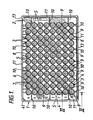
- the test tray 1 has an oblong rectangular and flat upper wall surface 2 opening into which are ninety six chambers 3 disposed in a spaced array similarly to a conventional microtiter plate. In this array there are eight rows extending parallel to a longer side edge of the face 2 with twelve chambers 3 in each row and the chambers are spaced to provide twelve parallel columns with eight chambers in each column extending perpendicularly to the rows.
- the rows are identified by the letters A to H shown in Figure 1 and the columns by the numerals 1 to 12 shown in Figure 1, these letters and numerals are moulded into the surface 2 so that by reference thereto each chamber may be individually identified.
- the chambers 3 are identical and parallel to each other and each is formed by a tubular wall 4 extending downwardly from the top opening thereof in the upper wall 2 to provide a bottom opening or outlet port 5.
- the lower part length 6 of each chamber 3 is cylindrical and communicates with a co-axial frusto conical upper part length 7 which tapers to converge from the top opening to the cylindrical chamber part 6.
- the outlet port 5 is formed by an annular flange 8 at the bottom end of the tubular wall 4 and which provides a shoulder within the chamber 3.
- the tubular walls 4 are maintained in their spaced array by their moulding into the upper wall 2, by upstanding webs 9 which interconnect each tubular wall 4 to the tubular walls 4 adjacent thereto and also by a spaced array of upstanding webs 10 which interconnect the webs 9 (and possibly the tubular walls 4) to a peripheral side wall 11.
- the side wall extends downwardly from the periphery of the upper wall 2 and surrounds the array of tubular walls 4 in the test tray.
- the webs 9 and 10 serve to reinforce the structure of the tray and their form will be apparent to persons skilled in the art of injection moulding.
- each tubular wall 4 for a chamber projects downwardly beyond the lowermost edges 9a and 10a of the webs 9 and 10 respectively to form tubular spigots 12.
- the bottom end of the peripheral wall 11 is formed as a peripheral skirt 13 which extends downwardly beyond the lowermost edges 9a and 10a similarly to the tubular spigots 12.
- the collection tray 72 has an upper wall surface 15 opening into which is a spaced array of ninety six wells 16.
- the wells 16 are identical to each other and disposed in rows and columns which correspond to the rows and columns of the chambers 3 (particularly with respect to the tubular spigots 12).
- the upper surface 15 has (not shown) moulded-in identification letters A to H and numerals 1 to 12 in a similar manner to the test tray 1 so that each individual well 16 can readily be identified by reference to the indicia letters and numerals.
- the profile of the surface 15 corresponds to that of the surface 2.
- Each well is formed by a cylindrical tubular wall part 18 which forms a mouth 19 in the upper wall 15 from which it extends downwardly and the bottom end of the well is closed by a hemispherical wall part 20.
- the well walls 18 are retained in their spaced array and in parallel relationship with each other by the upper surface wall 15, upstanding webs 21 which interconnect each tubular wall 18 with the tubular walls 18 adjacent thereto, and upstanding webs 22 which interconnect the webs 21 (or possibly the walls 18) with a peripheral side wall 23 of the collection tray.
- the webs 21 and 22 are similar to the webs 9 and 10 and the peripheral side wall 23 extends downwardly from the upper surface wall 15 to surround the wells.
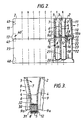
- the sectioned part illustrates chambers 3 and wells 16 in columns G and H only - it being appreciated that chambers and wells are similarly provided in the rows indicated at A to F.
- test tray 1 In use it is intended that the test tray 1 will be mounted in overlying relationship on the collection plate 72 with the upper wall surfaces 2 and 15 similarly orientated for the reference letters A to H and reference numerals 1 to 12 to correspond in directly overlying relationship.
- the trays engage for the skirt 13 of the test tray 1 to receive the upper surface 15 of the collection tray 72 in substantially complementary manner while the tubular spigots 12 are received within the mouths 19 of the corresponding wells 16 as shown in Figure 2.
- the depth to which the tubular spigots 12 enter the wells 16 is determined by the abutment of the lower edges 9a and 10a of the webs in the test tray on the upper wall surface 15 of the collection tray.
- the depth of insertion of the tubular spigots can be restricted by abutment of the peripheral edge of the upper wall surface 15 against an internal shoulder formed by the skirt 13 on the test tray.
- a selective separation medium will be carried in each of the chambers 3 of the test tray. Liquid under analysis is intended to flow over or through the separation medium and pass from the outlet ports 5 to be deposited in the wells 16 with which the tubular spigots 12 respectively communicate.
- the tray assembly and test tray 1 illustrated are primarily intended for use in conducting a chromatographic assay and a selective chromatographic medium is located in each of the chambers 3 in a similar manner to the previously mentioned known extraction cartridges sold under the Trade Mark BOND ELUT.
- the chromatographic medium has been omitted from the test tray in Figures 1 and 2 but such a medium is shown at 30 in the chamber 3 of Figure 3.
- the chromatographic medium is in the form of a cylindrical plug 30 which is closely received within the cylindrical bore 6 of the chamber between an underlying cylindrical frit 31 and an overlying cylindrical frit 32.
- the frits 31 and 32 are typically nylon filters which are closely received in the cylindrical bore 6 so that the cylindrical surfaces of the chromatographic plug 30 and frits 31 and 32 make face-to-face contact with the bore 6.
- the plug 30 is retained in the bottom of the chamber 3 by abutment of the lower frit 31 against the internal shoulder formed by the annular flange 8.
- the test tray 1 will be commercially available with selective chromatographic mediums 30 and frits 31, 32 fitted so that the trays will be purchased as appropriate for an intended assay.
- the chromatographic medium can be inserted in the chambers in powder, slurry or other form.
- test liquid or liquids which are to be analysed are pipetted or otherwise deposited in each of the chambers 3 so that such liquid in its flow through the chambers 3 is subjected to the chromatographic medium 30 in that chamber and the liquid emerging from the outlet ports 5, the percolate or eluate as the case may be, is collected in the respective wells 16 to be available for analysis.
- the trays of the assembly are particularly intended to be suitable for handling by automatic equipment where it is likely that the test liquid or liquids will be pipetted simultaneously into the eight chambers A to H of the first column and the remaining columns of chambers are then successively charged with the test liquid.
- the frusto conical part 7 of the chamber 3 is desirable to provide a relatively large reservoir for the test liquid.
- the collection tray 72 will conveniently be orientated so that the identification grid of letters A to H and numerals 1 to 12 correspond between the overlying trays and the references by which a particular chamber 3 is identified are the same as those for identifying the well 16 with which that chamber communicates.
- co-operating means may be provided between the test and collection trays so that such means inter-engages when the trays are correctly orientated to be mounted one on the other (as shown in Figure 2) but will not permit such mounting when the trays are incorrectly orientated with respect to each other.
- the co-operating means may simply comprise a track and track follower formed at corresponding corners of the test tray and the collection tray (as indicated at 40 in Figure 2) and which track and track follower must inter-engage as the test tray is fitted to the top of the collection tray to permit the correct mounting.
- the equipment may be programmed to sense the presence or absence of a particular location on the trays from which their correct orientation relative to the equipment and to each other may be determined; for example corresponding corners of the trays may be provided with upstanding chamfers or flats 41 on their respective side walls which are intended to be sensed by automatic handling equipment to ensure that the two trays are correctly orientated with respect to each other.
- the percolate or eluate liquid resulting from a chromatographic assay is collected in the wells 16, it will be appreciated from Figure 2 that the penetration of the tubular spigots 12 into the mouths of the respective wells alleviates the possibility of cross contamination between the liquids which emerge from the respective outlet ports 5. Furthermore the volume of each well 16 below the level of the bottom end face of the tubular spigot which it receives is sufficient to accommodate all of the percolate of eluate liquid which results from the respective chambers 3. Desirably therefore the aforementioned volume of each well is greater than the volume of each chamber 3 (although it is appreciated that the volume of test liquid which is deposited in each chamber 3 will often be the same as or less than the volume of the chamber 3 above the level of the uppermost frit 32).
- test and collection trays may be subjected to centrifugal forces and/or gas or air pressure differentials to promote the rate of liquid flow through the separation medium.
Landscapes
- Health & Medical Sciences (AREA)
- Chemical & Material Sciences (AREA)
- Immunology (AREA)
- Life Sciences & Earth Sciences (AREA)
- Hematology (AREA)
- Engineering & Computer Science (AREA)
- Molecular Biology (AREA)
- Analytical Chemistry (AREA)
- General Health & Medical Sciences (AREA)
- Urology & Nephrology (AREA)
- Biomedical Technology (AREA)
- Food Science & Technology (AREA)
- Cell Biology (AREA)
- Microbiology (AREA)
- Biotechnology (AREA)
- Chemical Kinetics & Catalysis (AREA)
- Clinical Laboratory Science (AREA)
- Medicinal Chemistry (AREA)
- Physics & Mathematics (AREA)
- Biochemistry (AREA)
- General Physics & Mathematics (AREA)
- Pathology (AREA)
- Investigating Or Analysing Biological Materials (AREA)
- Automatic Analysis And Handling Materials Therefor (AREA)
- Sampling And Sample Adjustment (AREA)
- Devices For Use In Laboratory Experiments (AREA)
- Saccharide Compounds (AREA)
- Agricultural Chemicals And Associated Chemicals (AREA)
- Medicinal Preparation (AREA)
- Table Devices Or Equipment (AREA)
- Packaging Frangible Articles (AREA)
- Pharmaceuticals Containing Other Organic And Inorganic Compounds (AREA)
- Acyclic And Carbocyclic Compounds In Medicinal Compositions (AREA)
- Analysing Materials By The Use Of Radiation (AREA)
- Optical Measuring Cells (AREA)
Applications Claiming Priority (2)
| Application Number | Priority Date | Filing Date | Title |
|---|---|---|---|
| GB9009308A GB2243446B (en) | 1990-04-25 | 1990-04-25 | An assay tray and assembly |
| GB9009308 | 1990-04-25 |
Publications (3)
| Publication Number | Publication Date |
|---|---|
| EP0454315A2 true EP0454315A2 (fr) | 1991-10-30 |
| EP0454315A3 EP0454315A3 (en) | 1992-02-19 |
| EP0454315B1 EP0454315B1 (fr) | 1995-06-14 |
Family
ID=10674984
Family Applications (1)
| Application Number | Title | Priority Date | Filing Date |
|---|---|---|---|
| EP91303083A Expired - Lifetime EP0454315B1 (fr) | 1990-04-25 | 1991-04-08 | Plateau d'analyse |
Country Status (13)
| Country | Link |
|---|---|
| EP (1) | EP0454315B1 (fr) |
| JP (1) | JPH04227860A (fr) |
| AT (1) | ATE123666T1 (fr) |
| CA (1) | CA2040733C (fr) |
| DE (1) | DE69110346T2 (fr) |
| DK (1) | DK0454315T3 (fr) |
| ES (1) | ES2073121T3 (fr) |
| FI (1) | FI911981A7 (fr) |
| GB (1) | GB2243446B (fr) |
| GR (1) | GR3017127T3 (fr) |
| IE (1) | IE66894B1 (fr) |
| NO (1) | NO911622L (fr) |
| PT (1) | PT97444B (fr) |
Cited By (6)
| Publication number | Priority date | Publication date | Assignee | Title |
|---|---|---|---|---|
| EP0816309A1 (fr) * | 1996-06-14 | 1998-01-07 | Eli Lilly And Company | Procédé combinatoire à l'aide de composés capteurs pour la préparation de bibliothèques de composés d'urée et de thiourée |
| EP0818431A1 (fr) * | 1996-06-14 | 1998-01-14 | Eli Lilly And Company | Procédé combinatoire à l'aide de composés capteurs pour la préparation de bibliothèques de composés d'amine secondaire |
| EP0825164A3 (fr) * | 1996-06-14 | 1998-10-28 | Eli Lilly And Company | Procédé combinatoire à l'aide de composés capteurs pour la préparation de bibliothèques d'amides, de carbamates et de sulfonamides |
| EP0816310A3 (fr) * | 1996-06-14 | 1999-02-24 | Eli Lilly And Company | Procédé combinatoire à l'aide de composés capteurs pour la préparation de bibliothèques de composés d'amine tertiaire |
| WO2006074155A3 (fr) * | 2005-01-05 | 2006-09-28 | Promega Corp | Dispositif et procede de separation de molecules |
| CN102909108A (zh) * | 2012-11-16 | 2013-02-06 | 安图实验仪器(郑州)有限公司 | 分层反应杯板架 |
Families Citing this family (5)
| Publication number | Priority date | Publication date | Assignee | Title |
|---|---|---|---|---|
| ES2249818T3 (es) * | 1997-06-09 | 2006-04-01 | F. Hoffmann-La Roche Ag | Dispositivo desechable despues de su uso en un proceso. |
| EP1232792B1 (fr) * | 2001-02-20 | 2006-09-06 | F. Hoffmann-La Roche Ag | Matrice linéaire de cuvettes, matrice bidimensionnelle de cuvettes construite avec une telle matrice linéaire et système comprenant de telles matrices bidimensionnelles de cuvettes |
| GB0118620D0 (en) * | 2001-07-31 | 2001-09-19 | Macaulay Land Use Res Inst The | Apparatus and method |
| EP1491258B1 (fr) * | 2003-06-24 | 2008-12-03 | Millipore Corporation | Systeme de vide multifonctionnelle |
| JP5515096B2 (ja) * | 2010-10-28 | 2014-06-11 | 独立行政法人海洋研究開発機構 | 自動分析前処理装置及び自動分析前処理装置を備えた自動分析装置 |
Family Cites Families (12)
| Publication number | Priority date | Publication date | Assignee | Title |
|---|---|---|---|---|
| US4111754A (en) * | 1976-11-29 | 1978-09-05 | Hydow Park | Immunological testing devices and methods |
| US4246339A (en) * | 1978-11-01 | 1981-01-20 | Millipore Corporation | Test device |
| US4734192A (en) * | 1982-07-01 | 1988-03-29 | Millipore Corporation | Multiwell membrane filtration apparatus |
| US4599315A (en) * | 1983-09-13 | 1986-07-08 | University Of California Regents | Microdroplet test apparatus |
| DE3407849A1 (de) * | 1984-02-29 | 1985-08-29 | Alois 3201 Algermissen Höft | Verfahren und einrichtung zum gleichzeitigen aufbringen einer vielzahl von fluessigkeitsproben auf einen objekttraeger |
| DE3416933A1 (de) * | 1984-05-04 | 1985-11-07 | Dora 1000 Berlin Köhler | Mit antigenen oder antikoerpern beschichteter traeger |
| GB2164866B (en) * | 1984-10-02 | 1988-05-05 | Water Res Centre | Automatic filtration apparatus |
| EP0184571A1 (fr) * | 1984-11-28 | 1986-06-11 | Etablissements Pasture et Cie. | Colonne d'extraction et/ou de filtration |
| US4895706A (en) * | 1986-10-28 | 1990-01-23 | Costar Corporation | Multi-well filter strip and composite assemblies |
| US4797259A (en) * | 1986-12-15 | 1989-01-10 | Pall Corporation | Well-type diagnostic plate device |
| US4832842A (en) * | 1987-12-28 | 1989-05-23 | Limb Glenn R | Filter chest for use with multiple filter units, for laboratories, and with the filter units |
| US5108704A (en) * | 1988-09-16 | 1992-04-28 | W. R. Grace & Co.-Conn. | Microfiltration apparatus with radially spaced nozzles |
-
1990
- 1990-04-25 GB GB9009308A patent/GB2243446B/en not_active Revoked
-
1991
- 1991-04-08 DE DE69110346T patent/DE69110346T2/de not_active Expired - Fee Related
- 1991-04-08 AT AT91303083T patent/ATE123666T1/de not_active IP Right Cessation
- 1991-04-08 ES ES91303083T patent/ES2073121T3/es not_active Expired - Lifetime
- 1991-04-08 EP EP91303083A patent/EP0454315B1/fr not_active Expired - Lifetime
- 1991-04-08 DK DK91303083.9T patent/DK0454315T3/da active
- 1991-04-08 IE IE115491A patent/IE66894B1/en not_active IP Right Cessation
- 1991-04-18 CA CA002040733A patent/CA2040733C/fr not_active Expired - Fee Related
- 1991-04-23 PT PT97444A patent/PT97444B/pt not_active IP Right Cessation
- 1991-04-24 NO NO91911622A patent/NO911622L/no unknown
- 1991-04-24 JP JP3094403A patent/JPH04227860A/ja active Pending
- 1991-04-24 FI FI911981A patent/FI911981A7/fi not_active Application Discontinuation
-
1995
- 1995-08-16 GR GR950402246T patent/GR3017127T3/el unknown
Cited By (6)
| Publication number | Priority date | Publication date | Assignee | Title |
|---|---|---|---|---|
| EP0816309A1 (fr) * | 1996-06-14 | 1998-01-07 | Eli Lilly And Company | Procédé combinatoire à l'aide de composés capteurs pour la préparation de bibliothèques de composés d'urée et de thiourée |
| EP0818431A1 (fr) * | 1996-06-14 | 1998-01-14 | Eli Lilly And Company | Procédé combinatoire à l'aide de composés capteurs pour la préparation de bibliothèques de composés d'amine secondaire |
| EP0825164A3 (fr) * | 1996-06-14 | 1998-10-28 | Eli Lilly And Company | Procédé combinatoire à l'aide de composés capteurs pour la préparation de bibliothèques d'amides, de carbamates et de sulfonamides |
| EP0816310A3 (fr) * | 1996-06-14 | 1999-02-24 | Eli Lilly And Company | Procédé combinatoire à l'aide de composés capteurs pour la préparation de bibliothèques de composés d'amine tertiaire |
| WO2006074155A3 (fr) * | 2005-01-05 | 2006-09-28 | Promega Corp | Dispositif et procede de separation de molecules |
| CN102909108A (zh) * | 2012-11-16 | 2013-02-06 | 安图实验仪器(郑州)有限公司 | 分层反应杯板架 |
Also Published As
| Publication number | Publication date |
|---|---|
| GB2243446A (en) | 1991-10-30 |
| PT97444A (pt) | 1993-07-30 |
| FI911981A0 (fi) | 1991-04-24 |
| FI911981A7 (fi) | 1991-10-26 |
| EP0454315A3 (en) | 1992-02-19 |
| NO911622L (no) | 1991-10-28 |
| CA2040733C (fr) | 1995-07-18 |
| GB2243446B (en) | 1994-05-25 |
| IE66894B1 (en) | 1996-02-07 |
| GR3017127T3 (en) | 1995-11-30 |
| ES2073121T3 (es) | 1995-08-01 |
| DE69110346T2 (de) | 1995-10-12 |
| PT97444B (pt) | 1998-08-31 |
| EP0454315B1 (fr) | 1995-06-14 |
| CA2040733A1 (fr) | 1991-10-26 |
| IE911154A1 (en) | 1991-11-06 |
| DK0454315T3 (da) | 1995-08-07 |
| JPH04227860A (ja) | 1992-08-17 |
| GB9009308D0 (en) | 1990-06-20 |
| DE69110346D1 (de) | 1995-07-20 |
| ATE123666T1 (de) | 1995-06-15 |
| NO911622D0 (no) | 1991-04-24 |
Similar Documents
| Publication | Publication Date | Title |
|---|---|---|
| US5417923A (en) | Assay tray assembly | |
| US8007743B2 (en) | Multifunctional vacuum manifold | |
| US4895706A (en) | Multi-well filter strip and composite assemblies | |
| US4948564A (en) | Multi-well filter strip and composite assemblies | |
| US7318911B2 (en) | Membrane filtered pipette tip | |
| US6464942B2 (en) | Plate alignment and sample transfer indicia for a multiwell multiplate stack and method for processing biological/chemical samples using the same | |
| US5906796A (en) | Solid phase extraction plate | |
| US4798706A (en) | Device for holding horizontal array of liquid aliquots | |
| CA2040733C (fr) | Plateau pour analyse chromatographique | |
| US3969250A (en) | Apparatus for preparing liquid samples for analysis in automatic analyzers | |
| EP1395645B1 (fr) | Trous d'acces de plaque de filtre multipuits pour appareil d'essai multipuits | |
| EP1547686A1 (fr) | Plaque de microtitrage, système et méthode pour le traitement d'échantillons | |
| EP0185330A2 (fr) | Système de traitement pour des échantillons multiples | |
| EP1056540B1 (fr) | Dispositifs servant a preparer des echantillons pour essai | |
| JP2003088357A (ja) | 微量試料処理装置 | |
| EP0871544B1 (fr) | Dispositif de filtration pour echantillons multiples | |
| WO2001005507A1 (fr) | Procede, appareil et dispositif de filtration centrifuge a ecoulement inverse | |
| US7438862B2 (en) | Apparatus for simultaneous processing of multiple samples | |
| US20050095175A1 (en) | Support and stand-off ribs for underdrain for multi-well device | |
| EP1724019B1 (fr) | Récepteur plaque avec sections transversales multiples | |
| EP1397212A2 (fr) | Broche de positionnement pour appareil d'essai multipuits | |
| US20030226796A1 (en) | Modular system for separating components of a liquid sample | |
| US6800491B2 (en) | Robotic reservoir without liquid hangup | |
| EP1491258B1 (fr) | Systeme de vide multifonctionnelle | |
| US20240116051A1 (en) | Device and Method for Separating Blood Plasma from Whole Blood |
Legal Events
| Date | Code | Title | Description |
|---|---|---|---|
| PUAI | Public reference made under article 153(3) epc to a published international application that has entered the european phase |
Free format text: ORIGINAL CODE: 0009012 |
|
| AK | Designated contracting states |
Kind code of ref document: A2 Designated state(s): AT BE CH DE DK ES FR GB GR IT LI LU NL SE |
|
| PUAL | Search report despatched |
Free format text: ORIGINAL CODE: 0009013 |
|
| AK | Designated contracting states |
Kind code of ref document: A3 Designated state(s): AT BE CH DE DK ES FR GB GR IT LI LU NL SE |
|
| 17P | Request for examination filed |
Effective date: 19920407 |
|
| 17Q | First examination report despatched |
Effective date: 19940131 |
|
| GRAA | (expected) grant |
Free format text: ORIGINAL CODE: 0009210 |
|
| AK | Designated contracting states |
Kind code of ref document: B1 Designated state(s): AT BE CH DE DK ES FR GB GR IT LI LU NL SE |
|
| REF | Corresponds to: |
Ref document number: 123666 Country of ref document: AT Date of ref document: 19950615 Kind code of ref document: T |
|
| REF | Corresponds to: |
Ref document number: 69110346 Country of ref document: DE Date of ref document: 19950720 |
|
| ET | Fr: translation filed | ||
| REG | Reference to a national code |
Ref country code: ES Ref legal event code: FG2A Ref document number: 2073121 Country of ref document: ES Kind code of ref document: T3 |
|
| ITF | It: translation for a ep patent filed | ||
| REG | Reference to a national code |
Ref country code: DK Ref legal event code: T3 |
|
| REG | Reference to a national code |
Ref country code: GR Ref legal event code: FG4A Free format text: 3017127 |
|
| PLBE | No opposition filed within time limit |
Free format text: ORIGINAL CODE: 0009261 |
|
| STAA | Information on the status of an ep patent application or granted ep patent |
Free format text: STATUS: NO OPPOSITION FILED WITHIN TIME LIMIT |
|
| 26N | No opposition filed | ||
| PGFP | Annual fee paid to national office [announced via postgrant information from national office to epo] |
Ref country code: AT Payment date: 19970414 Year of fee payment: 7 |
|
| PGFP | Annual fee paid to national office [announced via postgrant information from national office to epo] |
Ref country code: GR Payment date: 19970422 Year of fee payment: 7 |
|
| PGFP | Annual fee paid to national office [announced via postgrant information from national office to epo] |
Ref country code: NL Payment date: 19970428 Year of fee payment: 7 Ref country code: LU Payment date: 19970428 Year of fee payment: 7 Ref country code: ES Payment date: 19970428 Year of fee payment: 7 |
|
| PGFP | Annual fee paid to national office [announced via postgrant information from national office to epo] |
Ref country code: BE Payment date: 19970529 Year of fee payment: 7 |
|
| PG25 | Lapsed in a contracting state [announced via postgrant information from national office to epo] |
Ref country code: LU Free format text: LAPSE BECAUSE OF NON-PAYMENT OF DUE FEES Effective date: 19980408 Ref country code: AT Free format text: LAPSE BECAUSE OF NON-PAYMENT OF DUE FEES Effective date: 19980408 |
|
| PGFP | Annual fee paid to national office [announced via postgrant information from national office to epo] |
Ref country code: FR Payment date: 19980409 Year of fee payment: 8 |
|
| PG25 | Lapsed in a contracting state [announced via postgrant information from national office to epo] |
Ref country code: ES Free format text: LAPSE BECAUSE OF EXPIRATION OF PROTECTION Effective date: 19980411 |
|
| PGFP | Annual fee paid to national office [announced via postgrant information from national office to epo] |
Ref country code: SE Payment date: 19980416 Year of fee payment: 8 |
|
| PGFP | Annual fee paid to national office [announced via postgrant information from national office to epo] |
Ref country code: DK Payment date: 19980417 Year of fee payment: 8 |
|
| PG25 | Lapsed in a contracting state [announced via postgrant information from national office to epo] |
Ref country code: GR Free format text: LAPSE BECAUSE OF NON-PAYMENT OF DUE FEES Effective date: 19980430 Ref country code: BE Free format text: LAPSE BECAUSE OF NON-PAYMENT OF DUE FEES Effective date: 19980430 |
|
| REG | Reference to a national code |
Ref country code: CH Ref legal event code: PUE Owner name: PFIZER INC. TRANSFER- PORVAIR SCIENCES LIMITED |
|
| REG | Reference to a national code |
Ref country code: FR Ref legal event code: TP |
|
| BERE | Be: lapsed |
Owner name: PFIZER INC. Effective date: 19980430 |
|
| PG25 | Lapsed in a contracting state [announced via postgrant information from national office to epo] |
Ref country code: NL Free format text: LAPSE BECAUSE OF NON-PAYMENT OF DUE FEES Effective date: 19981101 |
|
| NLV4 | Nl: lapsed or anulled due to non-payment of the annual fee |
Effective date: 19981101 |
|
| PGFP | Annual fee paid to national office [announced via postgrant information from national office to epo] |
Ref country code: GB Payment date: 19990408 Year of fee payment: 9 |
|
| PG25 | Lapsed in a contracting state [announced via postgrant information from national office to epo] |
Ref country code: SE Free format text: LAPSE BECAUSE OF NON-PAYMENT OF DUE FEES Effective date: 19990409 |
|
| PGFP | Annual fee paid to national office [announced via postgrant information from national office to epo] |
Ref country code: CH Payment date: 19990413 Year of fee payment: 9 |
|
| PGFP | Annual fee paid to national office [announced via postgrant information from national office to epo] |
Ref country code: DE Payment date: 19990419 Year of fee payment: 9 |
|
| PG25 | Lapsed in a contracting state [announced via postgrant information from national office to epo] |
Ref country code: DK Free format text: LAPSE BECAUSE OF NON-PAYMENT OF DUE FEES Effective date: 19990430 |
|
| REG | Reference to a national code |
Ref country code: GB Ref legal event code: 732E |
|
| PG25 | Lapsed in a contracting state [announced via postgrant information from national office to epo] |
Ref country code: FR Free format text: LAPSE BECAUSE OF NON-PAYMENT OF DUE FEES Effective date: 19991231 |
|
| EUG | Se: european patent has lapsed |
Ref document number: 91303083.9 |
|
| REG | Reference to a national code |
Ref country code: FR Ref legal event code: ST |
|
| REG | Reference to a national code |
Ref country code: DK Ref legal event code: EBP |
|
| PG25 | Lapsed in a contracting state [announced via postgrant information from national office to epo] |
Ref country code: GB Free format text: LAPSE BECAUSE OF NON-PAYMENT OF DUE FEES Effective date: 20000408 |
|
| PG25 | Lapsed in a contracting state [announced via postgrant information from national office to epo] |
Ref country code: LI Free format text: LAPSE BECAUSE OF NON-PAYMENT OF DUE FEES Effective date: 20000430 Ref country code: CH Free format text: LAPSE BECAUSE OF NON-PAYMENT OF DUE FEES Effective date: 20000430 |
|
| REG | Reference to a national code |
Ref country code: ES Ref legal event code: FD2A Effective date: 20000601 |
|
| GBPC | Gb: european patent ceased through non-payment of renewal fee |
Effective date: 20000408 |
|
| REG | Reference to a national code |
Ref country code: CH Ref legal event code: PL |
|
| PG25 | Lapsed in a contracting state [announced via postgrant information from national office to epo] |
Ref country code: DE Free format text: LAPSE BECAUSE OF NON-PAYMENT OF DUE FEES Effective date: 20010201 |
|
| PG25 | Lapsed in a contracting state [announced via postgrant information from national office to epo] |
Ref country code: IT Free format text: LAPSE BECAUSE OF NON-PAYMENT OF DUE FEES;WARNING: LAPSES OF ITALIAN PATENTS WITH EFFECTIVE DATE BEFORE 2007 MAY HAVE OCCURRED AT ANY TIME BEFORE 2007. THE CORRECT EFFECTIVE DATE MAY BE DIFFERENT FROM THE ONE RECORDED. Effective date: 20050408 |