EP0454483A2 - Movement vector detection device - Google Patents
Movement vector detection device Download PDFInfo
- Publication number
- EP0454483A2 EP0454483A2 EP91303795A EP91303795A EP0454483A2 EP 0454483 A2 EP0454483 A2 EP 0454483A2 EP 91303795 A EP91303795 A EP 91303795A EP 91303795 A EP91303795 A EP 91303795A EP 0454483 A2 EP0454483 A2 EP 0454483A2
- Authority
- EP
- European Patent Office
- Prior art keywords
- operation means
- image
- movement
- operating
- outputs
- Prior art date
- Legal status (The legal status is an assumption and is not a legal conclusion. Google has not performed a legal analysis and makes no representation as to the accuracy of the status listed.)
- Granted
Links
Images

Classifications
-
- G—PHYSICS
- G06—COMPUTING OR CALCULATING; COUNTING
- G06T—IMAGE DATA PROCESSING OR GENERATION, IN GENERAL
- G06T7/00—Image analysis
- G06T7/20—Analysis of motion
- G06T7/269—Analysis of motion using gradient-based methods
-
- G—PHYSICS
- G06—COMPUTING OR CALCULATING; COUNTING
- G06T—IMAGE DATA PROCESSING OR GENERATION, IN GENERAL
- G06T7/00—Image analysis
- G06T7/20—Analysis of motion
- G06T7/223—Analysis of motion using block-matching
- G06T7/238—Analysis of motion using block-matching using non-full search, e.g. three-step search
Definitions
- the present invention relates to a movement detection device, and more specifically, to a device which detects movement vectors from image signals.
- a method to detect movement vectors by image signal processing is the time-space gradient method which is described in the Japanese Patent Publication No, 60-46878, in J.O, Limb and J,A, Murply, "Measuring the Speed of Moving Objects from Television Signals", IEEE Trans, Com., Com-23, 4, pp. 474-487 (April 1975) and in others.
- ⁇ ⁇ B d ⁇ sign(g′y)/ ⁇ B
- ⁇ B means the computed grand total in a block and "sign( )" is the function which outputs the signal of "g ′ x " and "g′ y ".
- the detection range has no limits, if the spacial concentration distribution of the input images is liner, that is, if the space gradient of the image concentration is constant.
- the spacial concentration distribution of image varies in random cycles, and therefore, the conventional method has the disadvantage of not being easily applicable to large movements.
- the first objective of the present invention is to provide a movement vector detection device which solves the aforesaid disadvantage.
- the second objective of the present invention is to provide a movement vector detection device which has a wide detection range to images, the space gradient of which is not constant but changes randomly.
- the third objective of the present invention is to provide a movement vector detection device that is capable of more accurately detecting the movement vector of images whose space gradient changes with time and is capable of being applied to large movement images, because, in the space gradient computation, the average space gradient is computed under given weights of the preceding image plane and the current image plane.
- the fourth objective of the present invention is to provide a movement vector detection device which has an enhanced detection range of movement vectors without any substantial extension of circuits.
- a preferred embodiment of the present invention discloses a movement detection device comprising concentration difference operation means which operates the concentration difference between images; space gradient operation means which operates the space gradient in an image plane, averaging means which averages, with giving predetermined weights, the outputs of the space gradient operation means for images different in time, and movement vector operation means which operates the movement vector of the image, based on the outputs of the concentration difference operation means and of the averaging means.
- a movement detection device comprising a concentration difference operation means which operates the concentration difference between images, a space gradient operation means which operates the average space gradients, under predetermined weights, of the current and preceding image planes, correction means which corrects the concentration difference operated by the concentration difference operation means with the space gradient signal, a first totalizing means which totalizes the outputs of the correction means in a given block, second totalizing means which totalizes the absolute values of the average space gradient operated by the space gradient operation means in a given block, and division means which decides the output of the first totalizing means by the output of the second totalizing means, is disclosed.
- the fifth objective of the present invention is to provide a vibration correction device which corrects the image movement in accordance with the movement vector which is output from the vector detection unit.
- a preferred embodiment of the present invention discloses a movement adjustment device comprising concentration difference operation means which operates the concentration difference between image planes, space gradient operation means which operates the space gradient in an image plane, averaging means which averages, with giving predetermined weights, the outputs of the space gradient operation means for image planes different in time, movement vector operation means which operates the movement vector of image, based on the outputs of the concentration difference operation means and of the averaging means, correction means which corrects the movement of the image in accordance with the output of the movement vector operation means.
- the sixth objective of the present invention is to provide a video camera comprising a vibration correction function having a broad range of vibration detection.
- a preferred embodiment of the present invention discloses a video camera comprising image pickup means, a time gradient operation means which operates the time gradient between image planes from the image pickup signals that are output by the image pickup means, space gradient operation means which operates the space gradient in the image plane from the image pickup signals, averaging means which averages the outputs of the space gradient operation means with giving predetermined weights thereto, a movement vector operation means which operates the movement vector of the image in accordance with the outputs of the time gradient operation means and of the averaging means, and correction means which corrects the movement of the image in accordance with the output of the movement vector operation means.
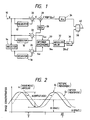
- Figure 1 shows the block diagram of an embodiment of the present invention
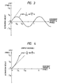
- Figure 2 shows the cross-section of an image pattern where the frequency is "T”
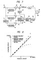
- Figure 3 shows the results of estimation when the movement amounts are estimated by the application of time-space gradient method to the frequency T pattern
- Figure 4 shows the results of estimation by the average gradient method
- Figure 5 shows the results of estimation by the embodiment of Figure 1
- Figure 6 illustrates the effective range of weights
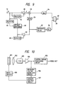
- Figure 7 shows the block diagram of another embodiment of the present invention
- Figure 8 compares the estimation results by a conventional example and the embodiment of Figure 7
- Figure 9 shows the block diagram of a third embodiment of the present invention
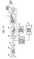
- Figures 10 and 11 show the block diagrams of embodiments where the movement vector detection devices in the present invention are each applied to the image vibration adjustment devices.
- Figure 1 shows the block diagram of an embodiment of the present invention.
- 10 is the input terminal of image signals
- 12 and 14 are the registers which memorize (that is, delay) the input signals for one field period (or one frame period);
- 16 and 18 are the registers which memorize (that is, delay) the input signals only for the scanning time of several pixels that are required for the operation of the space gradient of the image concentration distribution;
- 20, 22 and 24 are subtractors;
- 26 is the sign output circuit which outputs the signal showing the sign (positive, negative or zero) of the input signal (output of subtractor 24);
- 28 is the multiplier);
- 30 is the optimum averaging circuit which averages the two inputs after giving proper weights;
- 32 is the absolute value circuit which outputs the absolute value of the output signal of the optimum averaging circuit 30;
- 34 and 36 are the totalizing circuits which accumulate the data in the designated block for detection of the movement vector;
- 38 is the divider which divides the output of totalizing circuit 34 by the output of totalizing
- the image signal "g" which is input to input terminal 10 is separated into three channels, and firstly, the concentration difference between the time sequential two field (or frame) image planes, that is, the time gradient "d", is computed by register 12 and subtractor 20. Secondly, the space gradient "g d2 " of the current image plane (field or frame) is computed by register 16 and subtractor 22, and thirdly, the space gradient "g d1 " of the preceding image plane (field or frame) is computed by register 18 and subtractor 24 by the use of the image signal of the preceding field (or frame) of register 14.
- Absolute value circuit 32 takes up the absolute value of the output "g da " of optimum averaging circuit 30 and feeds it to totalizing circuit 36.
- Totalizing circuit 36 computes the total sum of the outputs "
- Sign output circuit 26 outputs "+1" if the space gradient "g d1 " is positive, “0” if g d1 is zero, and “-1” if g d1 is negative, and multiplier 28 multiplies the output of sign output circuit 26 by the time gradient "d" (the output of subtractor 20). Thus, the time gradient in the direction of space gradient is obtained.
- totalizing circuit 34 computes the total sum of the output of multiplier 28 for each block.
- the output of totalizing circuit 34 is sent to the numerator input of divider 38.
- Divider 38 divides the output of totalizing circuit 34 by the output of totalizing circuit 36. The result of division by divider 38 represents the movement amount in the direction of space gradient of each designated block, and the movement amount of each block in horizontal or vertical direction is obtained from output terminal 40.
- FIG. 7 shows a circuit block diagram of such modified embodiment.
- 42 represents a sign output circuit having the same function as that of the sign output circuit 42 in Figure 1, and is different from Figure 1 in that the output of optimum averaging circuit 30 is used as input.
- Other elements are same as in Figure 1 and they are numbered in the same way.
- the system is structured in such a way that the current image plane is referred to not just for the magnitude of the space gradient but also for its signal.
- Figure 9 shows a block diagram of yet another embodiment.
- 44 represents a register which gives the time lag for 1 field (or frame)
- 46 represents a similar optimum averaging circuit as optimum averaging circuit
- 48 represents a register which gives the time lag for the scanning time of several pixels
- 50 represents a subtractor.
- Optimum averaging circuit 46 averages, under a proper weight, the current image signal from input terminal 10 and the preceding image signal from register 44.
- Register 48 and subtractor 50 computes the space gradient from the output of optimum averaging circuit 46, and the output of subtractor 50 is sent to sign output circuit 26 and absolute value circuit 32.
- the concentration difference "d" has been obtained by register 12 and subtractor 20, as was already explained hereinabove. Therefore, the same processing proceeds thereafter, and the movement amount signal is obtained from output terminal 40.
- the present invention has the advantage of enhancing the detection range of movement vector, without substantial extension of circuits.
- Figures 10 and 11 each show an example where each of the aforesaid movement vector detection circuits is applied to video camera as the vibration correction (anti-vibration) device.
- Figure 10 shows an example which employs, as the anti-vibration unit, a movable top angle prism which optically corrects for the vibration by moving the light axis of the image lens.
- 101 represents a movable top angle prism which moves the direction of light axis of the image lens system, that is, the top angle thereof, and which, by way of example, is a pair of parallel glass sheets having a silicon-based fluid in-between.
- 102 represents an image lens
- 103 represents a CCD or other image sensor which converts the optical image captured by image lens into electronic signals and transmits them as output
- 104 represents a preamplifier
- 105 represents a camera signal processing circuit which outputs the standardized image signals after giving blanking processing, addition of synchronizing signals, gamma correction and other processing to the image signals that are output from the image sensor
- 106 represents the movement vector detection circuit described in the respective embodiments of Figures 1, 7 and 9
- 107 represents the system control circuit which picks up image movement vector data supplied by movement vector detection circuit 106, computes the data on the drive direction of the movable top angle prism so as to offset the movement of the image by vibration, and computes the drive amount required for correction
- 108 represents the drive circuit which drives top angle prism 101 in accordance with the data computed by system control circuit 107.
- movement vectors arising from image vibration is detected by the movement vector detection circuit of each said embodiment, the direction and amount of drive for the movable top angle prism are computed in accordance with these movement vectors, and vibration correction is made by the drive of the movable top angle prism.
- Figure 11 shows an example which employs no optical correction device, but corrects the movement of image by first taking the image temporarily into the memory device and then changing the read-out range from the memory device.
- Image signals which are output from preamplifier 104 are converted to digital signals by A/D converter 109 and are fed into the memory device of digital signal processing circuit 110.
- Memory control circuit 113 controls the rate and timing of A/D conversion for the image take-up into the memory device as well as the timing and address of the write-in into the memory device. This memory control circuit 113 also controls the address and timing of read-out from the memory device.
- the digital image signals that are read out from memory 110 are given various camera signal processings by camera signal processing circuit 111, are converted to analog signals by D/A conversion circuit 112, and then are output as image signals. It is also possible to set up the system in such a way that the digital signals are output as such.
- Movement vector detection circuit 115 detects the movement vector caused by camera vibration, in the same way as in the embodiment of Figure 1; and the movement vector thus detected is fed to system control circuit 114, which in turn computes the direction and magnitude of the image movement, based on the movement vector detected by movement vector detection circuit 115, and then based thereon controls memory control circuit 113 and controls the memory read-out range. That is, the memory takes up in advance the image in a larger image angle than that to be output, and at the time of memory read-out, the movement is corrected by changing the range of its read-out.
- the movement vector detection circuit is not only applicable to vibration correction, but also, as movement detector, to camera panning detection and many other applications.
- the present invention provides a video camera equipped with a high performance vibration correction function which has a very broad range of movement detection and is capable of detecting and making correction for both large and small movements.
Landscapes
- Engineering & Computer Science (AREA)
- Multimedia (AREA)
- Computer Vision & Pattern Recognition (AREA)
- Physics & Mathematics (AREA)
- General Physics & Mathematics (AREA)
- Theoretical Computer Science (AREA)
- Image Analysis (AREA)
- Compression Or Coding Systems Of Tv Signals (AREA)
- Studio Circuits (AREA)
Abstract
Description
- The present invention relates to a movement detection device, and more specifically, to a device which detects movement vectors from image signals.
- A method to detect movement vectors by image signal processing is the time-space gradient method which is described in the Japanese Patent Publication No, 60-46878, in J.O, Limb and J,A, Murply, "Measuring the Speed of Moving Objects from Television Signals", IEEE Trans, Com., Com-23, 4, pp. 474-487 (April 1975) and in others. In this time-space gradient method, the movement amount of each point is computed by the following basic formula:


- In the conventional examples, the detection range has no limits, if the spacial concentration distribution of the input images is liner, that is, if the space gradient of the image concentration is constant. In practice, however, the spacial concentration distribution of image varies in random cycles, and therefore, the conventional method has the disadvantage of not being easily applicable to large movements.
- Therefore, the first objective of the present invention is to provide a movement vector detection device which solves the aforesaid disadvantage.
- The second objective of the present invention is to provide a movement vector detection device which has a wide detection range to images, the space gradient of which is not constant but changes randomly.
- The third objective of the present invention is to provide a movement vector detection device that is capable of more accurately detecting the movement vector of images whose space gradient changes with time and is capable of being applied to large movement images, because, in the space gradient computation, the average space gradient is computed under given weights of the preceding image plane and the current image plane.
- The fourth objective of the present invention is to provide a movement vector detection device which has an enhanced detection range of movement vectors without any substantial extension of circuits.
- In order to achieve such an objective, a preferred embodiment of the present invention discloses a movement detection device comprising concentration difference operation means which operates the concentration difference between images; space gradient operation means which operates the space gradient in an image plane, averaging means which averages, with giving predetermined weights, the outputs of the space gradient operation means for images different in time, and movement vector operation means which operates the movement vector of the image, based on the outputs of the concentration difference operation means and of the averaging means.
- In a preferred embodiment of the present invention, a movement detection device comprising a concentration difference operation means which operates the concentration difference between images, a space gradient operation means which operates the average space gradients, under predetermined weights, of the current and preceding image planes, correction means which corrects the concentration difference operated by the concentration difference operation means with the space gradient signal, a first totalizing means which totalizes the outputs of the correction means in a given block, second totalizing means which totalizes the absolute values of the average space gradient operated by the space gradient operation means in a given block, and division means which decides the output of the first totalizing means by the output of the second totalizing means, is disclosed.
- The fifth objective of the present invention is to provide a vibration correction device which corrects the image movement in accordance with the movement vector which is output from the vector detection unit.
- In order to achieve such an objective, a preferred embodiment of the present invention discloses a movement adjustment device comprising concentration difference operation means which operates the concentration difference between image planes, space gradient operation means which operates the space gradient in an image plane, averaging means which averages, with giving predetermined weights, the outputs of the space gradient operation means for image planes different in time, movement vector operation means which operates the movement vector of image, based on the outputs of the concentration difference operation means and of the averaging means, correction means which corrects the movement of the image in accordance with the output of the movement vector operation means.
- The sixth objective of the present invention is to provide a video camera comprising a vibration correction function having a broad range of vibration detection.
- In order to achieve such an objective, a preferred embodiment of the present invention discloses a video camera comprising image pickup means, a time gradient operation means which operates the time gradient between image planes from the image pickup signals that are output by the image pickup means, space gradient operation means which operates the space gradient in the image plane from the image pickup signals, averaging means which averages the outputs of the space gradient operation means with giving predetermined weights thereto, a movement vector operation means which operates the movement vector of the image in accordance with the outputs of the time gradient operation means and of the averaging means, and correction means which corrects the movement of the image in accordance with the output of the movement vector operation means.
- Other objectives and characteristics of the present invention will be made clear by the ensuing specifications and drawings.
- Figure 1 shows the block diagram of an embodiment of the present invention, Figure 2 shows the cross-section of an image pattern where the frequency is "T", Figure 3 shows the results of estimation when the movement amounts are estimated by the application of time-space gradient method to the frequency T pattern, Figure 4 shows the results of estimation by the average gradient method, Figure 5 shows the results of estimation by the embodiment of Figure 1, Figure 6 illustrates the effective range of weights, Figure 7 shows the block diagram of another embodiment of the present invention, Figure 8 compares the estimation results by a conventional example and the embodiment of Figure 7, Figure 9 shows the block diagram of a third embodiment of the present invention, and Figures 10 and 11 show the block diagrams of embodiments where the movement vector detection devices in the present invention are each applied to the image vibration adjustment devices.
- With reference to the drawings, embodiments of the movement vector detection devices of the present invention are explained below.
- Figure 1 shows the block diagram of an embodiment of the present invention. 10 is the input terminal of image signals, 12 and 14 are the registers which memorize (that is, delay) the input signals for one field period (or one frame period); 16 and 18 are the registers which memorize (that is, delay) the input signals only for the scanning time of several pixels that are required for the operation of the space gradient of the image concentration distribution; 20, 22 and 24 are subtractors; 26 is the sign output circuit which outputs the signal showing the sign (positive, negative or zero) of the input signal (output of subtractor 24); 28 is the multiplier); 30 is the optimum averaging circuit which averages the two inputs after giving proper weights; 32 is the absolute value circuit which outputs the absolute value of the output signal of the optimum
averaging circuit 30; 34 and 36 are the totalizing circuits which accumulate the data in the designated block for detection of the movement vector; 38 is the divider which divides the output of totalizingcircuit 34 by the output of totalizingcircuit 36; 40 is the output terminal of the signal which shows the image movement amount in horizontal or vertical direction. - An explanation of actions in Figure 1 is given as follows. The image signal "g" which is input to
input terminal 10 is separated into three channels, and firstly, the concentration difference between the time sequential two field (or frame) image planes, that is, the time gradient "d", is computed by register 12 andsubtractor 20. Secondly, the space gradient "gd2" of the current image plane (field or frame) is computed byregister 16 andsubtractor 22, and thirdly, the space gradient "gd1" of the preceding image plane (field or frame) is computed by register 18 andsubtractor 24 by the use of the image signal of the preceding field (or frame) ofregister 14. - Optimum
averaging circuit 30 gives the optimum weight to the space gradients "gd1" and "gd2" of between the preceding and current image planes and averages them. For example, if gd1: gd2 = 3:1, optimum averagingcircuit 30 outputs an average value "gda" which is expressed by:
-
Absolute value circuit 32 takes up the absolute value of the output "gda" of optimumaveraging circuit 30 and feeds it to totalizingcircuit 36. Totalizingcircuit 36 computes the total sum of the outputs "|gda|" ofabsolute value circuit 32 in the block consisting of a prescribed number of pixels, and sends the total sum to the denominator input ofdivider 38, - Sign
output circuit 26 outputs "+1" if the space gradient "gd1" is positive, "0" if gd1 is zero, and "-1" if gd1 is negative, andmultiplier 28 multiplies the output ofsign output circuit 26 by the time gradient "d" (the output of subtractor 20). Thus, the time gradient in the direction of space gradient is obtained. And totalizingcircuit 34 computes the total sum of the output ofmultiplier 28 for each block. The output of totalizingcircuit 34 is sent to the numerator input ofdivider 38.Divider 38 divides the output of totalizingcircuit 34 by the output of totalizingcircuit 36. The result of division bydivider 38 represents the movement amount in the direction of space gradient of each designated block, and the movement amount of each block in horizontal or vertical direction is obtained fromoutput terminal 40. - Next, with reference to Figures 2 through 5, the optimum determination method and its effect at optimum
averaging circuit 30 are explained, For the propose of simplification, the image concentration distribution is assumed as one of the one-dimensional sine curve, and its graph is shown in Figure 2. In Figure 2, the vertical axis shows the concentration value of the image, and the horizontal axis shows the position in the image plane, "A" represents the height of the sine curve, "B" represents the bias, "T" represents the cycle, "g₁" represents the image before movement, and "g₂" represents the image after it moved by "α". The following can be said if the time-space gradient method is applied to the sine curve shown in Figure 2. When expressing the time gradient as "d(x)" and the partial derivative of g₁ in x direction (space gradient) as "g d₁(x)", then:

- where: ω = 2π/T
- Consequently, the estimated movement amount "e(α)" is given from the aforesaid basic formula as:

circuits 
Figure 3 is the illustration of the above where the horizontal axis shows the movement amount "α" of the pixel unit and the vertical axis represents the extimation result of the pixel unit. - Likewise, the estimation result when simply averaging the gradients of two field (or frame) images is:

- This is illustrated in Figure 4. Of assuming the image as one of the sine curves, the average gradient becomes zero when the movement amount is T/2 and therefore the estimation results disperses at α = T/2, but such phenomena cannot take place in reality. Generally, some characteristics improvement is achieved by averaging the space gradients of the preceding and current field (or frame) images rather than by only using the space gradient of the preceding field (or frame) image which serves as the base.
- Next, by the extension of the idea of averaging the space gradients, it is conceived that such averaging be done with optimum weighing. Normally, if the reference ratio of the space gradient of the base preceding field (or frame) image and the space gradient of the current field (or frame) is n:1, then the estimation result in this case is expressed by the following formula:

- where: ω = 2π/T
Formula (7) is equal to formula (5) when n = +∞ and to formula (6) when n=1. Estimation results when n=2, 3 and 4 are illustrated in Figure 5. Comparison of it with Figures 3 and 4 shows that the detection range is considerably broadened, particularly when n=3. - Next, the effective range of n which is the reference specific gravity of the space gradient of the preceding image plane to the space gradient of the current image plane, is explained. If the conditions are such that, when the movement amount "α" = ±T/8, the error between the true value (namely ±T/8) and the estimation result is no more than ±5%, the range of reference specific gravity "n" for it to be effective for the weighing can be:

- The estimation results when n = 1.4 and when n = 9 are shown in Figure 6.
- When n = 1, that is, when the simple average gradient method is employed, the ratio of error to the true value when α = ±T/8 is 5.5%, and when n=∞, that is, when the conventional method which uses the space gradient of the preceding image plane only, an error of 10% occurs, but the use of weighted average gradient within the range of 1.4 ≦ n ≦ 9 controls the error to no more than ±5%. The foregoing is the result of mathematical explanation for the usefulness of the weighted average space gradient method, based on the assumption that the change of image concentration is one of the sine curves.
- With reference to Figure 7, a second embodiment is explained. In the circuit of Figure 1, the sign of the space gradient of the preceding image plane was used in order to obtain the numerator of the estimation formula, but it is also possible to use the sign of the value after the weighed averaging of the space gradient, that is, the output of
optimum averaging circuit 30 in Figure 1. In the latter case, the current image plane is referred to, not just for the magnitude of the space gradient but also for its sign, and improvement of characteristics can be expected. Figure 7 shows a circuit block diagram of such modified embodiment. 42 represents a sign output circuit having the same function as that of thesign output circuit 42 in Figure 1, and is different from Figure 1 in that the output ofoptimum averaging circuit 30 is used as input. Other elements are same as in Figure 1 and they are numbered in the same way. In other words, the system is structured in such a way that the current image plane is referred to not just for the magnitude of the space gradient but also for its signal. - Using the 256 x 256 x 1 (byte) image as an example, the conventional time-space gradient method, the average gradient method by which the space gradients are averaged simply with the weight ratio of 1:1, and the weighed average gradient method in accordance with the embodiment of Figure 7 are compared with respect to the image signals that have undergone low-pass filtering treatment. The results of comparison are shown in Figure 8. In Figure 8, "X" represents the estimation result by the conventional space time gradient method without averaging "○" represents the estimation result by the average gradient method, and "□" represents the estimation result by the present embodiment. The weight was made to be (preceding image plane) : (current image plane) = 3:1. It is clear that the detection range has been substantially enhanced in comparison with the other two methods.
- Figure 9 shows a block diagram of yet another embodiment. The same elements as those in Figure 1 are numbered in the same way. 44 represents a register which gives the time lag for 1 field (or frame), 46 represents a similar optimum averaging circuit as
optimum averaging circuit Optimum averaging circuit 46 averages, under a proper weight, the current image signal frominput terminal 10 and the preceding image signal fromregister 44.Register 48 andsubtractor 50 computes the space gradient from the output ofoptimum averaging circuit 46, and the output ofsubtractor 50 is sent to signoutput circuit 26 andabsolute value circuit 32. The concentration difference "d" has been obtained byregister 12 andsubtractor 20, as was already explained hereinabove. Therefore, the same processing proceeds thereafter, and the movement amount signal is obtained fromoutput terminal 40. - In the system of Figure 9, one register which gives the times lag for the scanning time of several pixesls in the system of Figure 1 or Figure 7 is not required, making it possible to simplify the hardware configuration by that much.
- As is easily understandable from the aforesaid explanation, the present invention has the advantage of enhancing the detection range of movement vector, without substantial extension of circuits.
- Figures 10 and 11 each show an example where each of the aforesaid movement vector detection circuits is applied to video camera as the vibration correction (anti-vibration) device.
- Figure 10 shows an example which employs, as the anti-vibration unit, a movable top angle prism which optically corrects for the vibration by moving the light axis of the image lens. In Figure 10, 101 represents a movable top angle prism which moves the direction of light axis of the image lens system, that is, the top angle thereof, and which, by way of example, is a pair of parallel glass sheets having a silicon-based fluid in-between. 102 represents an image lens; 103 represents a CCD or other image sensor which converts the optical image captured by image lens into electronic signals and transmits them as output; 104 represents a preamplifier; 105 represents a camera signal processing circuit which outputs the standardized image signals after giving blanking processing, addition of synchronizing signals, gamma correction and other processing to the image signals that are output from the image sensor; 106 represents the movement vector detection circuit described in the respective embodiments of Figures 1, 7 and 9; 107 represents the system control circuit which picks up image movement vector data supplied by movement
vector detection circuit 106, computes the data on the drive direction of the movable top angle prism so as to offset the movement of the image by vibration, and computes the drive amount required for correction; and 108 represents the drive circuit which drivestop angle prism 101 in accordance with the data computed bysystem control circuit 107. - In this way, movement vectors arising from image vibration (camera vibration) is detected by the movement vector detection circuit of each said embodiment, the direction and amount of drive for the movable top angle prism are computed in accordance with these movement vectors, and vibration correction is made by the drive of the movable top angle prism.
- The explanation on the mechanism of the movement vector detection circuit by itself is omitted here because it was made in the aforesaid embodiments,
- Figure 11 shows an exemple which employs no optical correction device, but corrects the movement of image by first taking the image temporarily into the memory device and then changing the read-out range from the memory device.
- The same elements as those in Figure 10 are numbered in the same way, and explanations thereof are omitted.
- Image signals which are output from
preamplifier 104 are converted to digital signals by A/D converter 109 and are fed into the memory device of digitalsignal processing circuit 110.Memory control circuit 113 controls the rate and timing of A/D conversion for the image take-up into the memory device as well as the timing and address of the write-in into the memory device. Thismemory control circuit 113 also controls the address and timing of read-out from the memory device. - The digital image signals that are read out from
memory 110 are given various camera signal processings by camerasignal processing circuit 111, are converted to analog signals by D/A conversion circuit 112, and then are output as image signals. It is also possible to set up the system in such a way that the digital signals are output as such. - Movement
vector detection circuit 115 detects the movement vector caused by camera vibration, in the same way as in the embodiment of Figure 1; and the movement vector thus detected is fed to system control circuit 114, which in turn computes the direction and magnitude of the image movement, based on the movement vector detected by movementvector detection circuit 115, and then based thereon controlsmemory control circuit 113 and controls the memory read-out range. That is, the memory takes up in advance the image in a larger image angle than that to be output, and at the time of memory read-out, the movement is corrected by changing the range of its read-out. - In the aforesaid system, it is possible to place the camera signal processing circuit downstream of D/
A converter 112 and to let it perform analog processing, but digital signal processing provides easier processing and less noise. - In this way, correction for vibration of video camera can be made by the movement vector detection circuit of the present invention. The movement vector detection circuit is not only applicable to vibration correction, but also, as movement detector, to camera panning detection and many other applications.
- The present invention provides a video camera equipped with a high performance vibration correction function which has a very broad range of movement detection and is capable of detecting and making correction for both large and small movements.
Claims (31)
- A movement detecting device comprising:(A) concentration difference operation means for operating a concentration difference between image planes;(B) space gradient operation means for operating a space gradient in the image plane;(C) averaging means for averaging, with giving predetermined weights, the outputs of said space gradient operation means for each of the image planes difference in time; and(D) movement vector operation means for operating the movement vectors of the image, based on the outputs of said concentration difference operation means and of said averaging means.
- A movement detecting device according to Claim 1, wherein said concentration difference operation means detects the time gradient of image planes between the fields or frames.
- A movement detecting device according to Claim 1, wherein said space gradient operation means detects the concentration difference among a predetermined number of pixels in the image plane.
- A movement detecting device according to Claim 1, wherein the weight given by said averaging means is greater for a preceding image plane than for a current image plane.
- A movement detecting device according to Claim 1, wherein said movement vector operation means outputs the aggregate total movement vector of all movement vectors in a predetermined block of the image plane.
- A movement detecting device according to Claim 5, wherein said movement vector operation means comprises:(a) correction means for detecting the sign of the said space gradient operation means, and for correcting the output of said concentration difference operation means in accordance with said sign;(b) absolute value operation means for providing the absolute value of the output of said averaging means;(c) first totalizing means for operating the aggregate total of outputs of said absolute value operation means for said predetermined block;(d) second totalizing means for operating the aggregate total of outputs of said concentration difference operation means, as corrected by said correction means, for said predetermined block; and(e) division means for operating the quotient of the outputs of said first totalizing means and said second totalizing means.
- A movement detecting device according to Claim 5, further comprising:(a) correcting means for detecting the sign of the output of said averaging operation means, and for correcting the output of said concentration difference operation means in accordance with said sign;(b) absolute value operation means for providing the absolute value of the output of said averaging means;(c) first totalizing means for operating the aggregate total of outputs of said absolute value operation means for said predetermined block;(d) second totalizing means for operating the aggregate total of outputs of said concentration difference operation means, as corrected by said correction means, for said predetermined block; and(e) division means for operating the quotient of the outputs of said first totalizing means and said second totalizing means.
- A movement detecting device comprising:(A) concentration difference operation means for operating a concentration difference between image planes;(B) arranging means for averaging, with giving predetermined weights, the image planes different in time;(C) space gradient operation means for operating the space gradient of the output of said averaging means; and(D) movement vector operation means for operating the movement vector of the time, based on the outputs of the said concentration difference operation means and of the said space gradient operation means.
- A movement detecting device according to Claim 8, wherein said concentration difference operation means detects the time gradient of image planes, and said space gradient operation means detects the concentration difference among a predetermined number of pixels in the image plane.
- A movement detecting device according to Claim 8, wherein the weight given by said averaging means is greater for a preceding image plane than for a current image plane.
- A movement detecting device according to Claim 8, which said movement vector operation means outputs the aggregate total movement vector of all movement vectors in a certain block of the image plane.
- A movement detecting device according to Claim 8, further comprising:(a) correction means for detecting the sign of the output of said space gradient operation means, and for correcting the output of said concentration difference operation means in accordance with said sign;(b) absolute value operation means for operating the absolute value of the output of said space gradient operation means;(c) first totalizing means for operating the aggregate total of outputs of said absolute value operation means for said predetermined block;(d) second totalizing means for operating the aggregate total of outputs of said concentration difference operation means, as corrected by said correction means, for said predetermined block and(e) division means for operating the quotient of the outputs of said first totalizing means and said second totalizing means.
- A movement detecting device comprising:(A) time gradient operation means for operating a time gradient between image planes; and(B) space gradient operation means for operating a space gradient in the image plane; and(C) averaging means for averaging, with giving predetermined weights, a plurality of outputs different in time, from said space gradient operation means; and(D) movement vector operation means for operating the movement vector of the image, based on the outputs of the said time gradient operation means and of said averaging means.
- A movement detecting device according to Claim 13, wherein said movement vector operation means operates the aggregate total of all movement vectors in a predetermined block in the image plane.
- A movement detecting device according to Claim 14, wherein said movement vector operation means comprises:(a) correction means for detecting the sign of the said space gradient operation means, and for correcting the output of said the gradient operation means in accordance with said sign;(b) absolute value operation means for operating the absolute value of the output of said averaging means;(c) first totalizing means for operating the aggregate total of outputs of said absolute value operation means for said predetermined block;(d) second totalizing means for operating the aggregate total of outputs of said concentration difference operation means, as corrected by said correction means, for said predetermined block; and(e) division means for operating the quotient of the outputs of said first totalizing means and the said second totalizing means.
- A movement detecting device comprising:(A) concentration difference operation means for operating a concentration difference between image planes;(B) space gradient operation means for operating a space gradient in an image plane;(C) averaging means for averaging, with giving predetermined weights, the output of each of the image planes different in time, from said space gradient operation means;(D) movement vector operation means for operating the movement vector of the image, based on the outputs of the said concentration difference operation means and of the said averaging means; and(E) correction means for correcting the movement of said image, in accordance with the output of the said movement vector operation means.
- A movement detecting device according to Claim 16, wherein said correction means is an optical correction means which offsets the moment of image by changing an apex angle of a photographing light axis.
- A movement detecting device according to Claim 17, wherein said correction means comprises a variable apex angle prism.
- A movement detecting device according to Claim 16, further comprising memory means for memorizing an image of a preceding image plane, wherein a range of read-out of the memorized image from said memory means can be changed in accordance with the output of said movement vector operation means.
- A movement detecting device according to Claim 16, wherein said concentration difference operation means detects the image time gradient between fields or frames.
- A movement detecting device according to Claim 16, wherein said space gradient operation means detects the concentration difference among a predetermined number of pixels in the image plane.
- A movement detecting device according to Claim 16, wherein the weight given by said averaging means is greater for a preceding image plane than for a current plane.
- A movement detecting device according to Claim 16, wherein said movement vector operation means outputs the aggregate total movement vector of all movement vectors in a predetermined block of the image plane.
- A video camera comprising:(A) image pickup means;(B) time gradient operation means for operating the time gradient between image planes, out of an image pickup signal output from said image pickup means;(C) space gradient operation means for operating a space gradient in an image plane from said image pickup signal;(D) averaging means for averaging, with giving a predetermined weight, a plurality of outputs of said space gradient operation means;(E) movement vector operation means for operating the movement vector of the image, based on the outputs of the said time gradient operation means and of said averaging means; and(F) correction means for correcting the movement of said image, in accordance with the output of the said movement vector operation means.
- A movement detecting device according to Claim 24, wherein said movement vector operation means outputs the aggregate total movement vector of all movement vectors in a predetermined block of the image plane.
- A movement detecting device according to Claim 24, wherein said adjustment is an optical correction means which offsets the movement of image by changing an apex angle of a photographing light axis.
- A movement detecting device according to Claim 24, further comprising memory means for memorizing an image of a preceding image plane, wherein a range of read-out of the memorized image from said memory means can be changed in accordance with the output of said movement vector operation means.
- A method or apparatus for detecting movement in an input image in which change-of-image-with-time data and change-of-image-with-space data are used to detect the movement, the change-of-image-with-space data being obtained from a plurality of fields of the input image.
- A method or apparatus according to claim 28 which uses averaged change-of-image-with-space-data obtained by averaging together change-of-image-with-space data from a plurality of fields.
- A method or apparatus according to claim 28 which uses change-of-averaged-image-with-space data obtained using average image data provided by averaging image data from a plurality of fields.
- A method or apparatus according to claim 29 or claim 30 in which the averaging operation weights the data being averaged unequally.
Applications Claiming Priority (2)
| Application Number | Priority Date | Filing Date | Title |
|---|---|---|---|
| JP113952/90 | 1990-04-27 | ||
| JP11395290A JP2969781B2 (en) | 1990-04-27 | 1990-04-27 | Motion vector detection device |
Publications (3)
| Publication Number | Publication Date |
|---|---|
| EP0454483A2 true EP0454483A2 (en) | 1991-10-30 |
| EP0454483A3 EP0454483A3 (en) | 1993-08-18 |
| EP0454483B1 EP0454483B1 (en) | 1997-12-03 |
Family
ID=14625322
Family Applications (1)
| Application Number | Title | Priority Date | Filing Date |
|---|---|---|---|
| EP19910303795 Expired - Lifetime EP0454483B1 (en) | 1990-04-27 | 1991-04-26 | Movement vector detection device |
Country Status (3)
| Country | Link |
|---|---|
| EP (1) | EP0454483B1 (en) |
| JP (1) | JP2969781B2 (en) |
| DE (1) | DE69128298T2 (en) |
Cited By (4)
| Publication number | Priority date | Publication date | Assignee | Title |
|---|---|---|---|---|
| WO2001061027A1 (en) * | 2000-02-15 | 2001-08-23 | Kuraray Co., Ltd. | Processes for producing optically active 1,2-epoxy-2,6,6-trimethylcyclohexane methanol |
| WO2002093932A3 (en) * | 2001-05-11 | 2004-06-10 | Koninkl Philips Electronics Nv | Motion detection via image alignment |
| CN100409279C (en) * | 2003-01-16 | 2008-08-06 | 松下电器产业株式会社 | Image display device and image display method |
| US7483084B2 (en) | 2003-01-16 | 2009-01-27 | Panasonic Corporation | Image display apparatus and image display method |
Families Citing this family (1)
| Publication number | Priority date | Publication date | Assignee | Title |
|---|---|---|---|---|
| CA2291217C (en) | 1998-12-09 | 2004-09-21 | Kuraray Co., Ltd. | Vinyl alcohol polymer and its composition |
Family Cites Families (2)
| Publication number | Priority date | Publication date | Assignee | Title |
|---|---|---|---|---|
| FR2648254B2 (en) * | 1988-09-23 | 1991-08-30 | Thomson Csf | METHOD AND DEVICE FOR ESTIMATING MOTION IN A SEQUENCE OF MOVED IMAGES |
| JP6046878B2 (en) | 2011-03-25 | 2016-12-21 | 東芝ライテック株式会社 | Lamp apparatus and lighting apparatus |
-
1990
- 1990-04-27 JP JP11395290A patent/JP2969781B2/en not_active Expired - Fee Related
-
1991
- 1991-04-26 DE DE69128298T patent/DE69128298T2/en not_active Expired - Fee Related
- 1991-04-26 EP EP19910303795 patent/EP0454483B1/en not_active Expired - Lifetime
Cited By (4)
| Publication number | Priority date | Publication date | Assignee | Title |
|---|---|---|---|---|
| WO2001061027A1 (en) * | 2000-02-15 | 2001-08-23 | Kuraray Co., Ltd. | Processes for producing optically active 1,2-epoxy-2,6,6-trimethylcyclohexane methanol |
| WO2002093932A3 (en) * | 2001-05-11 | 2004-06-10 | Koninkl Philips Electronics Nv | Motion detection via image alignment |
| CN100409279C (en) * | 2003-01-16 | 2008-08-06 | 松下电器产业株式会社 | Image display device and image display method |
| US7483084B2 (en) | 2003-01-16 | 2009-01-27 | Panasonic Corporation | Image display apparatus and image display method |
Also Published As
| Publication number | Publication date |
|---|---|
| EP0454483B1 (en) | 1997-12-03 |
| DE69128298T2 (en) | 1998-04-09 |
| JP2969781B2 (en) | 1999-11-02 |
| EP0454483A3 (en) | 1993-08-18 |
| JPH0410885A (en) | 1992-01-16 |
| DE69128298D1 (en) | 1998-01-15 |
Similar Documents
| Publication | Publication Date | Title |
|---|---|---|
| EP0488723B1 (en) | Movement vector detection apparatus | |
| EP0656725B1 (en) | Image-shake correcting device | |
| CN101889452B (en) | Image generation device and image generation method | |
| EP0589643A1 (en) | Digital image stabilization using binary edge data | |
| US5943090A (en) | Method and arrangement for correcting picture steadiness errors in telecine scanning | |
| KR100232113B1 (en) | Motion vector detecting apparatus | |
| US5296925A (en) | Movement vector detection device | |
| EP0538042A2 (en) | Apparatus for judging a hand movement of an image | |
| US5173770A (en) | Movement vector detection device | |
| EP0454483B1 (en) | Movement vector detection device | |
| EP0488721B1 (en) | Movement detection | |
| CN111164406A (en) | Two-dimensional scintillation measuring device and two-dimensional scintillation measuring method | |
| US20070065126A1 (en) | Hand shake blur detecting apparatus | |
| JP3208264B2 (en) | Camera shake correction device and video camera using the same | |
| JP2641599B2 (en) | Motion vector detection device | |
| JP3200089B2 (en) | Motion vector detection device and shake correction device | |
| JP3157009B2 (en) | Motion vector detection device and blur correction device | |
| KR20040083822A (en) | A Moving Vector Detector of Camera Motion | |
| JP3126998B2 (en) | Motion vector detection device | |
| JP2600520B2 (en) | Image motion compensation device | |
| JPH05176218A (en) | Image motion correction device | |
| JP2910284B2 (en) | Moving vector detecting method and apparatus | |
| JPH04207480A (en) | motion vector detection device | |
| KR20040004297A (en) | Image distortion compensation method and devices for CMOS Image Sensor | |
| JPH0394586A (en) | Method for controlling vertical spatial frequency characteristic in solid-state image pickup element |
Legal Events
| Date | Code | Title | Description |
|---|---|---|---|
| PUAI | Public reference made under article 153(3) epc to a published international application that has entered the european phase |
Free format text: ORIGINAL CODE: 0009012 |
|
| AK | Designated contracting states |
Kind code of ref document: A2 Designated state(s): DE FR GB |
|
| PUAL | Search report despatched |
Free format text: ORIGINAL CODE: 0009013 |
|
| AK | Designated contracting states |
Kind code of ref document: A3 Designated state(s): DE FR GB |
|
| 17P | Request for examination filed |
Effective date: 19940107 |
|
| 17Q | First examination report despatched |
Effective date: 19950922 |
|
| GRAG | Despatch of communication of intention to grant |
Free format text: ORIGINAL CODE: EPIDOS AGRA |
|
| GRAH | Despatch of communication of intention to grant a patent |
Free format text: ORIGINAL CODE: EPIDOS IGRA |
|
| GRAH | Despatch of communication of intention to grant a patent |
Free format text: ORIGINAL CODE: EPIDOS IGRA |
|
| GRAA | (expected) grant |
Free format text: ORIGINAL CODE: 0009210 |
|
| AK | Designated contracting states |
Kind code of ref document: B1 Designated state(s): DE FR GB |
|
| REF | Corresponds to: |
Ref document number: 69128298 Country of ref document: DE Date of ref document: 19980115 |
|
| ET | Fr: translation filed | ||
| PLBE | No opposition filed within time limit |
Free format text: ORIGINAL CODE: 0009261 |
|
| STAA | Information on the status of an ep patent application or granted ep patent |
Free format text: STATUS: NO OPPOSITION FILED WITHIN TIME LIMIT |
|
| 26N | No opposition filed | ||
| REG | Reference to a national code |
Ref country code: GB Ref legal event code: IF02 |
|
| PGFP | Annual fee paid to national office [announced via postgrant information from national office to epo] |
Ref country code: GB Payment date: 20040413 Year of fee payment: 14 |
|
| PGFP | Annual fee paid to national office [announced via postgrant information from national office to epo] |
Ref country code: FR Payment date: 20040421 Year of fee payment: 14 Ref country code: DE Payment date: 20040421 Year of fee payment: 14 |
|
| PG25 | Lapsed in a contracting state [announced via postgrant information from national office to epo] |
Ref country code: GB Free format text: LAPSE BECAUSE OF NON-PAYMENT OF DUE FEES Effective date: 20050426 |
|
| PG25 | Lapsed in a contracting state [announced via postgrant information from national office to epo] |
Ref country code: DE Free format text: LAPSE BECAUSE OF NON-PAYMENT OF DUE FEES Effective date: 20051101 |
|
| GBPC | Gb: european patent ceased through non-payment of renewal fee |
Effective date: 20050426 |
|
| PG25 | Lapsed in a contracting state [announced via postgrant information from national office to epo] |
Ref country code: FR Free format text: LAPSE BECAUSE OF NON-PAYMENT OF DUE FEES Effective date: 20051230 |
|
| REG | Reference to a national code |
Ref country code: FR Ref legal event code: ST Effective date: 20051230 |