EP0454510A1 - Steuerkreis für einen hydraulischen, doppelt wirkenden Zylinder und ein Schieberventil für solch einen Kreislauf - Google Patents
Steuerkreis für einen hydraulischen, doppelt wirkenden Zylinder und ein Schieberventil für solch einen Kreislauf Download PDFInfo
- Publication number
- EP0454510A1 EP0454510A1 EP91400741A EP91400741A EP0454510A1 EP 0454510 A1 EP0454510 A1 EP 0454510A1 EP 91400741 A EP91400741 A EP 91400741A EP 91400741 A EP91400741 A EP 91400741A EP 0454510 A1 EP0454510 A1 EP 0454510A1
- Authority
- EP
- European Patent Office
- Prior art keywords
- chamber
- pressure
- fluid
- chambers
- circuit
- Prior art date
- Legal status (The legal status is an assumption and is not a legal conclusion. Google has not performed a legal analysis and makes no representation as to the accuracy of the status listed.)
- Granted
Links
- 239000012530 fluid Substances 0.000 claims abstract description 52
- 238000010586 diagram Methods 0.000 description 3
- 230000000694 effects Effects 0.000 description 3
- 230000000903 blocking effect Effects 0.000 description 2
- 230000005284 excitation Effects 0.000 description 2
- 230000006355 external stress Effects 0.000 description 2
- 238000011084 recovery Methods 0.000 description 2
- 239000000725 suspension Substances 0.000 description 2
- 238000007599 discharging Methods 0.000 description 1
- 238000009434 installation Methods 0.000 description 1
- 230000002427 irreversible effect Effects 0.000 description 1
- 238000002955 isolation Methods 0.000 description 1
- 230000035882 stress Effects 0.000 description 1
Images

Classifications
-
- F—MECHANICAL ENGINEERING; LIGHTING; HEATING; WEAPONS; BLASTING
- F15—FLUID-PRESSURE ACTUATORS; HYDRAULICS OR PNEUMATICS IN GENERAL
- F15B—SYSTEMS ACTING BY MEANS OF FLUIDS IN GENERAL; FLUID-PRESSURE ACTUATORS, e.g. SERVOMOTORS; DETAILS OF FLUID-PRESSURE SYSTEMS, NOT OTHERWISE PROVIDED FOR
- F15B11/00—Servomotor systems without provision for follow-up action; Circuits therefor
- F15B11/02—Systems essentially incorporating special features for controlling the speed or actuating force of an output member
-
- F—MECHANICAL ENGINEERING; LIGHTING; HEATING; WEAPONS; BLASTING
- F15—FLUID-PRESSURE ACTUATORS; HYDRAULICS OR PNEUMATICS IN GENERAL
- F15B—SYSTEMS ACTING BY MEANS OF FLUIDS IN GENERAL; FLUID-PRESSURE ACTUATORS, e.g. SERVOMOTORS; DETAILS OF FLUID-PRESSURE SYSTEMS, NOT OTHERWISE PROVIDED FOR
- F15B2211/00—Circuits for servomotor systems
- F15B2211/20—Fluid pressure source, e.g. accumulator or variable axial piston pump
- F15B2211/205—Systems with pumps
- F15B2211/2053—Type of pump
- F15B2211/20538—Type of pump constant capacity
-
- F—MECHANICAL ENGINEERING; LIGHTING; HEATING; WEAPONS; BLASTING
- F15—FLUID-PRESSURE ACTUATORS; HYDRAULICS OR PNEUMATICS IN GENERAL
- F15B—SYSTEMS ACTING BY MEANS OF FLUIDS IN GENERAL; FLUID-PRESSURE ACTUATORS, e.g. SERVOMOTORS; DETAILS OF FLUID-PRESSURE SYSTEMS, NOT OTHERWISE PROVIDED FOR
- F15B2211/00—Circuits for servomotor systems
- F15B2211/20—Fluid pressure source, e.g. accumulator or variable axial piston pump
- F15B2211/21—Systems with pressure sources other than pumps, e.g. with a pyrotechnical charge
- F15B2211/212—Systems with pressure sources other than pumps, e.g. with a pyrotechnical charge the pressure sources being accumulators
-
- F—MECHANICAL ENGINEERING; LIGHTING; HEATING; WEAPONS; BLASTING
- F15—FLUID-PRESSURE ACTUATORS; HYDRAULICS OR PNEUMATICS IN GENERAL
- F15B—SYSTEMS ACTING BY MEANS OF FLUIDS IN GENERAL; FLUID-PRESSURE ACTUATORS, e.g. SERVOMOTORS; DETAILS OF FLUID-PRESSURE SYSTEMS, NOT OTHERWISE PROVIDED FOR
- F15B2211/00—Circuits for servomotor systems
- F15B2211/30—Directional control
- F15B2211/305—Directional control characterised by the type of valves
- F15B2211/30505—Non-return valves, i.e. check valves
-
- F—MECHANICAL ENGINEERING; LIGHTING; HEATING; WEAPONS; BLASTING
- F15—FLUID-PRESSURE ACTUATORS; HYDRAULICS OR PNEUMATICS IN GENERAL
- F15B—SYSTEMS ACTING BY MEANS OF FLUIDS IN GENERAL; FLUID-PRESSURE ACTUATORS, e.g. SERVOMOTORS; DETAILS OF FLUID-PRESSURE SYSTEMS, NOT OTHERWISE PROVIDED FOR
- F15B2211/00—Circuits for servomotor systems
- F15B2211/40—Flow control
- F15B2211/405—Flow control characterised by the type of flow control means or valve
- F15B2211/40553—Flow control characterised by the type of flow control means or valve with pressure compensating valves
- F15B2211/40561—Flow control characterised by the type of flow control means or valve with pressure compensating valves the pressure compensating valve arranged upstream of the flow control means
-
- F—MECHANICAL ENGINEERING; LIGHTING; HEATING; WEAPONS; BLASTING
- F15—FLUID-PRESSURE ACTUATORS; HYDRAULICS OR PNEUMATICS IN GENERAL
- F15B—SYSTEMS ACTING BY MEANS OF FLUIDS IN GENERAL; FLUID-PRESSURE ACTUATORS, e.g. SERVOMOTORS; DETAILS OF FLUID-PRESSURE SYSTEMS, NOT OTHERWISE PROVIDED FOR
- F15B2211/00—Circuits for servomotor systems
- F15B2211/50—Pressure control
- F15B2211/505—Pressure control characterised by the type of pressure control means
- F15B2211/50509—Pressure control characterised by the type of pressure control means the pressure control means controlling a pressure upstream of the pressure control means
- F15B2211/50518—Pressure control characterised by the type of pressure control means the pressure control means controlling a pressure upstream of the pressure control means using pressure relief valves
- F15B2211/50527—Pressure control characterised by the type of pressure control means the pressure control means controlling a pressure upstream of the pressure control means using pressure relief valves using cross-pressure relief valves
-
- F—MECHANICAL ENGINEERING; LIGHTING; HEATING; WEAPONS; BLASTING
- F15—FLUID-PRESSURE ACTUATORS; HYDRAULICS OR PNEUMATICS IN GENERAL
- F15B—SYSTEMS ACTING BY MEANS OF FLUIDS IN GENERAL; FLUID-PRESSURE ACTUATORS, e.g. SERVOMOTORS; DETAILS OF FLUID-PRESSURE SYSTEMS, NOT OTHERWISE PROVIDED FOR
- F15B2211/00—Circuits for servomotor systems
- F15B2211/50—Pressure control
- F15B2211/505—Pressure control characterised by the type of pressure control means
- F15B2211/50509—Pressure control characterised by the type of pressure control means the pressure control means controlling a pressure upstream of the pressure control means
- F15B2211/50536—Pressure control characterised by the type of pressure control means the pressure control means controlling a pressure upstream of the pressure control means using unloading valves controlling the supply pressure by diverting fluid to the return line
-
- F—MECHANICAL ENGINEERING; LIGHTING; HEATING; WEAPONS; BLASTING
- F15—FLUID-PRESSURE ACTUATORS; HYDRAULICS OR PNEUMATICS IN GENERAL
- F15B—SYSTEMS ACTING BY MEANS OF FLUIDS IN GENERAL; FLUID-PRESSURE ACTUATORS, e.g. SERVOMOTORS; DETAILS OF FLUID-PRESSURE SYSTEMS, NOT OTHERWISE PROVIDED FOR
- F15B2211/00—Circuits for servomotor systems
- F15B2211/50—Pressure control
- F15B2211/515—Pressure control characterised by the connections of the pressure control means in the circuit
- F15B2211/5153—Pressure control characterised by the connections of the pressure control means in the circuit being connected to an output member and a directional control valve
- F15B2211/5154—Pressure control characterised by the connections of the pressure control means in the circuit being connected to an output member and a directional control valve being connected to multiple ports of an output member
-
- F—MECHANICAL ENGINEERING; LIGHTING; HEATING; WEAPONS; BLASTING
- F15—FLUID-PRESSURE ACTUATORS; HYDRAULICS OR PNEUMATICS IN GENERAL
- F15B—SYSTEMS ACTING BY MEANS OF FLUIDS IN GENERAL; FLUID-PRESSURE ACTUATORS, e.g. SERVOMOTORS; DETAILS OF FLUID-PRESSURE SYSTEMS, NOT OTHERWISE PROVIDED FOR
- F15B2211/00—Circuits for servomotor systems
- F15B2211/50—Pressure control
- F15B2211/515—Pressure control characterised by the connections of the pressure control means in the circuit
- F15B2211/5158—Pressure control characterised by the connections of the pressure control means in the circuit being connected to a pressure source and an output member
-
- F—MECHANICAL ENGINEERING; LIGHTING; HEATING; WEAPONS; BLASTING
- F15—FLUID-PRESSURE ACTUATORS; HYDRAULICS OR PNEUMATICS IN GENERAL
- F15B—SYSTEMS ACTING BY MEANS OF FLUIDS IN GENERAL; FLUID-PRESSURE ACTUATORS, e.g. SERVOMOTORS; DETAILS OF FLUID-PRESSURE SYSTEMS, NOT OTHERWISE PROVIDED FOR
- F15B2211/00—Circuits for servomotor systems
- F15B2211/50—Pressure control
- F15B2211/52—Pressure control characterised by the type of actuation
- F15B2211/526—Pressure control characterised by the type of actuation electrically or electronically
-
- F—MECHANICAL ENGINEERING; LIGHTING; HEATING; WEAPONS; BLASTING
- F15—FLUID-PRESSURE ACTUATORS; HYDRAULICS OR PNEUMATICS IN GENERAL
- F15B—SYSTEMS ACTING BY MEANS OF FLUIDS IN GENERAL; FLUID-PRESSURE ACTUATORS, e.g. SERVOMOTORS; DETAILS OF FLUID-PRESSURE SYSTEMS, NOT OTHERWISE PROVIDED FOR
- F15B2211/00—Circuits for servomotor systems
- F15B2211/60—Circuit components or control therefor
- F15B2211/665—Methods of control using electronic components
- F15B2211/6653—Pressure control
-
- F—MECHANICAL ENGINEERING; LIGHTING; HEATING; WEAPONS; BLASTING
- F15—FLUID-PRESSURE ACTUATORS; HYDRAULICS OR PNEUMATICS IN GENERAL
- F15B—SYSTEMS ACTING BY MEANS OF FLUIDS IN GENERAL; FLUID-PRESSURE ACTUATORS, e.g. SERVOMOTORS; DETAILS OF FLUID-PRESSURE SYSTEMS, NOT OTHERWISE PROVIDED FOR
- F15B2211/00—Circuits for servomotor systems
- F15B2211/60—Circuit components or control therefor
- F15B2211/665—Methods of control using electronic components
- F15B2211/6654—Flow rate control
-
- F—MECHANICAL ENGINEERING; LIGHTING; HEATING; WEAPONS; BLASTING
- F15—FLUID-PRESSURE ACTUATORS; HYDRAULICS OR PNEUMATICS IN GENERAL
- F15B—SYSTEMS ACTING BY MEANS OF FLUIDS IN GENERAL; FLUID-PRESSURE ACTUATORS, e.g. SERVOMOTORS; DETAILS OF FLUID-PRESSURE SYSTEMS, NOT OTHERWISE PROVIDED FOR
- F15B2211/00—Circuits for servomotor systems
- F15B2211/70—Output members, e.g. hydraulic motors or cylinders or control therefor
- F15B2211/705—Output members, e.g. hydraulic motors or cylinders or control therefor characterised by the type of output members or actuators
- F15B2211/7051—Linear output members
- F15B2211/7053—Double-acting output members
- F15B2211/7054—Having equal piston areas
Definitions
- the present invention is in the field of controlling hydraulic cylinders.
- Hydraulic cylinders are well-known components which transform the hydraulic energy they receive into mechanical energy, the latter possibly being considerable.
- Double-acting cylinders consist of a cylinder in which slides a piston dividing the cylinder into two chambers, the piston being connected to an outlet rod.
- a distribution system is controlled to admit fluid under pressure into one of the chambers, while the fluid contained in the other chamber is discharged into a low pressure tank, from which a high pressure pump draws, to allow the piston to move in the cylinder.
- the object of the invention is therefore to provide in the control circuit an auxiliary circuit which recovers the outlet fluid from the jack when its pressure exceeds a predetermined value, an auxiliary circuit which is simple and reliable in design and does not cause an increase. significant cost of the actuator control circuit.
- the invention provides a control circuit for a double-acting hydraulic cylinder consisting of a piston connected to an outlet rod and separating a cylinder into two chambers, the circuit comprising a source of pressurized fluid, a distribution system alternately placing one of the control chambers or chambers in communication with the source of pressurized fluid and the other controlled chamber or chambers in communication with a reservoir of low pressure fluids to control the movement of the cylinder piston.
- control circuit comprises an auxiliary circuit for preventing communication between the controlled chamber and the reservoir and interrupting the communication between the control chamber and the source of pressurized fluid when the pressure of the fluid in the controlled chamber reaches a predetermined value.
- the auxiliary circuit makes it possible to establish communication between the controlled chamber and the control chamber when the pressure of the fluid in the controlled chamber exceeds the predetermined value.
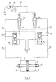
- FIG. 1 shows a known control circuit for a double-acting cylinder 10 divided by a piston 12 into two chambers 14 and 16, of variable volume.
- the piston is mounted on a rod 18.
- the hydraulic supply is provided by a pump 20, connected to a supply line 22 through a non-return valve 24.
- the supply line 22 is also connected to an accumulator of pressure 26.
- the control circuit comprises, for the chamber 14, a three-way solenoid valve 28, which puts a line 30 in communication, either with the high pressure line 22, or with a reservoir 25. When the solenoid valve 28 is not energized , it puts the line 30 in communication with the reservoir 25.
- the control circuit likewise comprises, for the chamber 16, a three-way solenoid valve 28 ′ which places a line 30 ′ in communication, that is to say with the high pressure line 22, either with the reservoir 25. When the solenoid valve 28 ′ is not energized, it puts the line 30 ′ in communication with the reservoir 25.
- the control circuit can be controlled by a computer or a microprocessor (not shown) which controls each of the solenoid valves 28,28 ′ and the pump 20 with, for example, a servo-control of the jack in position.
- Line 30 is connected, through a non-return valve 32, to line 34 supplying the chamber 14.
- Line 34 is also connected to the reservoir via a controlled valve 36.
- This valve is controlled by the pressure existing in line 30 ′, symmetrical with line 30, in the circuit corresponding to the second chamber 16 of the jack. If the solenoid valve 28 ′, symmetrical with the solenoid valve 28, which controls the pressure in the second chamber 16, is controlled, the pressure in the line 30 ′ causes the valve 36 to open and the chamber 14 to be turned on. tank. Conversely, if the solenoid valve 28 is energized, the pressure in the line 30 controls the opening of a valve 36 ′ which puts the chamber 16 in the reservoir. Thus, the chambers 14 and 16 are alternately one under pressure, the other at the tank.
- the two solenoid valves 28,28 ′ are at rest, the two chambers 14 and 16 are kept isolated by closing the valves 36,36 ′ and the non-return valves 32,32 ′.
- the invention proposes having an auxiliary circuit in the control circuit which comes into action as soon as the pressure in the controlled chamber exceeds that of the control chamber by a certain value.
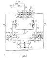
- FIG. 2 shows a control circuit according to the invention, in which the elements identical to those in Figure 1 have the same reference numerals.
- the control circuit is supplied as before by the pump 20 connected to the supply line 22 through a non-return valve 24, the line 22 being connected to a pressure accumulator 26 and supplying the solenoid valves 28 and 28 ′ through of a dispenser 50 which will be described later.
- the pipe 30 at the outlet of the solenoid valve 28 is connected to the pipe 34 for supplying the chamber 14 by means of a controlled valve 52.
- This valve 52 comprises a first chamber 54, into which the pipe 34 opens, containing a ball 56 loaded by a spring 58 towards a rest position where it prohibits communication to a second chamber 60 into which the pipe 30 opens.
- the second chamber 60 is delimited by a piston 62 carrying on one side a needle 64 susceptible to lift the ball 56 from its seat when the pressure in a third chamber 66 on the other side of the piston 62 causes the latter to move against the return spring 58 and the pressure prevailing in the chamber 54.
- the section of the piston 62 is identical to that of the seat of the ball 56.
- the third chamber 66 is in communication with the line 30 ′ symmetrical of the line 30 in the supply circuit of the chamber 16. It can thus be seen that the valve 52 is controlled by the pressure existing in the circuit 30 'corresponding to the second chamber 16 of the jack.
- This latter circuit comprises a valve 52 ′ identical to valve 52, its elements bearing the same numerical references assigned a "premium" therefore do not require a detailed description.
- the solenoid valve 28 ′ is energized, the solenoid valve 28 is left to stand.
- the pressure in line 22 is therefore transmitted through the distributor 50 and the solenoid valve 28 ′ in line 30 ′ and in the second chamber 60 ′.
- the ball 56 ′ lifts under the action of this pressure which is then transmitted via line 34 ′ to the chamber 16 of the jack.
- the pressure in the pipe 30 ′ is transmitted to the third chamber 66 of the valve 52, which has the effect of making move the piston 62 to the left considering Figure 2 and therefore lift the ball 56 from its seat, thus establishing communication between the first and second chambers 54 and 60, and therefore between the lines 30 and 14.
- the solenoid valve 28 not being excited, the pipe 30 communicates with the reservoir 25, and consequently the chamber 14 of the jack is therefore connected to the reservoir.
- the piston 12 can therefore move to the left.
- the chambers 14 and 16 are alternately one under pressure, the other at the reservoir. If, however, the two solenoid valves 28, 28 ′ are at rest, the two chambers 14 and 16 are kept isolated by closing the valves 52 and 52 ′.
- valves 52 and 52 ′ make it possible to dispense with having the non-return valves 32 and 32 ′ of FIG. 1 in the conduits 30 and 30 ′. If, for example, during an actuation of the jack, the pressure drops in the high pressure line 22, this would cause the valve 52 or 52 ′ to be closed which would be open and, consequently, the automatic isolation of chambers 14 and 16 , and therefore immobilization of the piston 12 in the position it occupied at the time when the damage in the hydraulic circuit appeared.
- the auxiliary circuit mainly comprises the distributor 50 disposed between the high pressure line 22 and the solenoid valves 28 and 28 ′.
- the distributor 50 consists of a drawer 100 sliding in a bore 102.
- This drawer has a central groove 104 between two bearing surfaces 106 and 108 cooperating in leaktight manner with the bore 102 to divide it into three chambers: an end chamber 110,112 on each side of the drawer and an annular central chamber 114 defined by the central groove 104.
- the drawer 100 is symmetrical and is held in the rest position in the middle of the bore 102 by springs 116 and 118 of the same rigidity on each side of the drawer.
- the auxiliary circuit also includes a line 120 connecting the chamber 110 with the line 34 ′, and a line 122 connecting the chamber 112 to the line 34.
- the high pressure line 22 opens into the central chamber 114 through an orifice which does not is never covered by staves 106 and 108.
- the bearing surface 106 cooperates with two orifices 124 and 126 so that the orifice 126 is uncovered and opens into the central chamber 114 when the drawer is in its central rest position or moved to the left, and is covered when the drawer 100 moves to the right (in Figure 2), while the orifice 124 is covered by the drawer in its central rest position or moved to the left, and uncovered and opens into the chamber 110 when the drawer is moved towards the right (in Figure 2).
- the two orifices 124 and 126 both communicate with a line 128 connected to the solenoid valve 28.
- the bearing surface 108 cooperates with two orifices 130 and 132 so that the orifice 130 is uncovered and opens into the central chamber 114 when the drawer is in its central rest position or moved to the right, and is covered when the drawer 100 moves to the left (in Figure 2), while the orifice 132 is covered by the drawer in its central rest position or moved to the right, and uncovered and opens into the chamber 112 when the drawer is moved to the left (in Figure 2).
- the two orifices 130 and 132 both communicate with a line 128 ′ connected to the solenoid valve 28 ′.
- the pump 20 In normal operation, if it is desired, for example, for the piston 12 of the cylinder to move to the right (in FIG. 2), the pump 20 is operated and the pressure in the line 22 is transmitted to the central chamber 114 of the distributor. 50. If for example the latter is at rest at this instant, the orifices 126 and 130 are exposed, and the fluid under pressure therefore reaches the solenoid valves 28 and 28 ′. If only the solenoid valve 28 is energized, the pressure is transmitted through line 30 in the second chamber 60 of the controlled valve 52. The ball 56 lifts under the action of this pressure which is then transmitted through line 34 to the chamber 14 of the cylinder.
- the pressure in the pipe 30 is transmitted to the third chamber 66 ′ of the valve 52 ′, which has the effect of causing the piston 62 ′ to move to the right by considering Figure 2 and therefore lifting the ball 56 ′ from its seat, thus establishing communication between the first and second chambers 54 ′ and 60 ′, and therefore between the pipes 30 ′ and 34 ′.
- the solenoid valve 28 ′ is not energized, the pipe 30 ′ communicates with the reservoir 25, and consequently the chamber 16 of the jack is therefore connected to the reservoir.
- the piston 12 can therefore move to the right.
- the chamber 16 is connected to the reservoir, the same applies to the chamber 110 of the distributor 50 via the conduit 120.
- the pressure prevailing in the chamber 14 is transmitted by the conduit 122, to the chamber 112 of the distributor 50.
- the imbalance of pressures on the two sides of the drawer 100 causes it to move to the left. In doing so, the range 106 continues to cover the orifice 124 and to discover the orifice 126.
- the solenoid valve 28 therefore continues to be supplied and the supply circuit of the chamber 14 is unchanged.
- the range 108 when it will cover the orifice 130 and discover the orifice 132.
- the pressure in the chamber 14 is therefore transmitted through the line 122 and the chamber 112 to the solenoid valve 28 ′, which is closed. We see that nothing changes in the return circuit of room 16.
- the pressure imbalance in the chambers 14 and 16 is transmitted to the chambers 110 and 112 on each side of the drawer 100 and causes that, the pressure in the chamber 110 being greater than that which prevails in the chamber 112, the drawer 100 moves to the right in FIG. 2.
- the slide covers the orifice 126, thereby interrupting the possibility of supply of pressurized fluid to the solenoid valve 28 by the source of pressurized fluid through the line 22, and discovers the orifice 124, and therefore allows the fluid in the controlled chamber 16 , under a pressure higher than that of the fluid in the control chamber 14, to be reinjected towards the solenoid valve 28 and then towards the chamber 14 if the solenoid valve is energized.
- the pressure in the chamber 16 is transmitted to the chamber 54 ′ of the valve 52 ′, the left face of the piston 62 ′ is subjected in the chamber 66 ′ to the pressure of the chamber 14 via the line 30 and the chamber 60 of valve 52, always subject to the pressure of chamber 14 of the jack.
- the section of the piston 62 ′ being equal to the section of the seat of the ball and the pressure in the chamber 54 ′, equal to that of the chamber 16, being slightly greater than or equal to the pressure in the chamber 66 ′, equal to that of chamber 14, the ball 56 ′ does not lift and prohibits the communication of chamber 16 with the reservoir 25.
- FIG. 3 a second embodiment of the auxiliary circuit according to the invention.
- the distributor 50 is identical to that of FIG. 2, except that the surfaces 106 and 108 of the drawer 100 each cooperate with a single port 126 and 130 respectively.
- the range 106 cooperates with the orifice 126 so that the orifice 126 is uncovered and opens into the chamber 114 when the drawer is in its rest position or moved to the left ( Figure 3) and is covered when the drawer 100 is moved to the right.
- the bearing surface 108 cooperates with the orifice 130 so that it is uncovered and opens into the cavity 114 when the drawer is in the central position or moved to the right in FIG. 3 and is covered when the drawer is moved towards left.
- Line 120 is connected to line 128 via a non-return valve 201, just as line 122 is connected to line 128 ′ via a non-return valve 202.
- the slide 100 In normal operation, if the difference between the pressures in the chambers 14 and 16 of the jack, and therefore in the chambers 112 and 110 respectively, is small, the slide 100 remains in the central position and the solenoid valves 28 and 28 ′ can be supplied by the high pressure line 22 via the chamber 114. If for example, the solenoid valve 28 ′ is energized and the external force is resistant, the piston 12 of the jack moves to the left under the effect of the increase in pressure in the chamber 16 as described above, which increase in pressure is also transmitted to the chamber 110 of the distributor 50. The slide 100 therefore moves to the right, the bearing 106 then covers the orifice 126, while the orifice 130 remains uncovered and allows the supply of the solenoid valve 28 ′.
- the non-return valve 202 prevents the communication of pressurized fluid to the chamber 112 of the distributor and to the chamber 14 of the jack.
- a non-return valve 203 can be provided on the high pressure line 22 to prevent a sudden rise in pressure in the chamber 16 from being transmitted, via the lines 120 and 128, the orifice 126 and the chamber 114, to the hydraulic supply device 20,26, before the slide 100 has moved. The hydraulic blocking of the jack is then ensured. Likewise, the non-return valve 203 ensures the hydraulic blocking of the jack in the case where the high pressure supply system 20-26 is at rest, or is broken down.
- a control circuit has therefore been produced in accordance with the invention for a double-acting cylinder of simple and reliable design and without significant additional cost. Indeed, in all cases, the movement of the piston of the jack is controlled by the excitation of a single solenoid valve 28 or 28 ′.
- the distributor 50 is sensitive to the difference in pressures in the chambers 14 and 16 of the cylinder, that is to say that it detects the direction of the external forces to which the rod of the cylinder is subjected. Depending on the direction detected, it will allow either the supply of pressurized fluid to the control chamber by the high pressure hydraulic supply device 20,26 if the external forces are resistant or weak, or the recovery of the pressurized fluid in the controlled chamber to supply it to the control chamber if the external forces are driving. An energy recovery is therefore obtained which would otherwise be lost in the low pressure tank 25, and a reduction in the consumption of hydraulic fluid of the control circuit.
- Such a device will find application in all active hydraulic systems, that is to say irreversible systems which use a clean energy source, to transform them into reactive systems according to the external conditions to which they are subjected.
Landscapes
- Engineering & Computer Science (AREA)
- Physics & Mathematics (AREA)
- Fluid Mechanics (AREA)
- Mechanical Engineering (AREA)
- General Engineering & Computer Science (AREA)
- Fluid-Pressure Circuits (AREA)
- Actuator (AREA)
Applications Claiming Priority (2)
| Application Number | Priority Date | Filing Date | Title |
|---|---|---|---|
| FR9005364A FR2661458B1 (fr) | 1990-04-27 | 1990-04-27 | Circuit de commande d'un verin hydraulique a double effet et distributeur a tiroir pour un tel circuit. |
| FR9005364 | 1990-04-27 |
Publications (2)
| Publication Number | Publication Date |
|---|---|
| EP0454510A1 true EP0454510A1 (de) | 1991-10-30 |
| EP0454510B1 EP0454510B1 (de) | 1994-06-08 |
Family
ID=9396141
Family Applications (1)
| Application Number | Title | Priority Date | Filing Date |
|---|---|---|---|
| EP19910400741 Expired - Lifetime EP0454510B1 (de) | 1990-04-27 | 1991-03-20 | Steuerkreis für einen hydraulischen, doppelt wirkenden Zylinder und ein Schieberventil für solch einen Kreislauf |
Country Status (5)
| Country | Link |
|---|---|
| EP (1) | EP0454510B1 (de) |
| JP (1) | JPH04228903A (de) |
| DE (1) | DE69102342T2 (de) |
| ES (1) | ES2054457T3 (de) |
| FR (1) | FR2661458B1 (de) |
Cited By (2)
| Publication number | Priority date | Publication date | Assignee | Title |
|---|---|---|---|---|
| DE19728850A1 (de) * | 1997-07-05 | 1999-01-07 | Festo Ag & Co | Verfahren und Vorrichtung zur Betätigung einer fluidisch betriebenen Stellvorrichtung |
| EP2495300A1 (de) | 2011-03-04 | 2012-09-05 | Unilever Plc, A Company Registered In England And Wales under company no. 41424 of Unilever House | Strukturierung von Waschmittelflüssigkeiten mit hydriertem Castoröl |
Families Citing this family (1)
| Publication number | Priority date | Publication date | Assignee | Title |
|---|---|---|---|---|
| CN109281879B (zh) * | 2018-11-22 | 2020-04-10 | 哈尔滨理工大学 | 一种四肢联动康复训练器用液压控制回路 |
Citations (3)
| Publication number | Priority date | Publication date | Assignee | Title |
|---|---|---|---|---|
| DE2235788A1 (de) * | 1971-07-23 | 1973-02-08 | Sperry Rand Ltd | Regelvorrichtung fuer hydraulische stellvorrichtungen |
| US4040439A (en) * | 1976-03-29 | 1977-08-09 | Eaton Corporation | Cushion valve arrangement |
| EP0052405A1 (de) * | 1980-11-14 | 1982-05-26 | Werkzeugmaschinenfabrik Oerlikon-Bührle AG | Einrichtung zum Regeln des Differenzdruckes an einem Hydromotor |
-
1990
- 1990-04-27 FR FR9005364A patent/FR2661458B1/fr not_active Expired - Lifetime
-
1991
- 1991-03-20 DE DE1991602342 patent/DE69102342T2/de not_active Expired - Fee Related
- 1991-03-20 EP EP19910400741 patent/EP0454510B1/de not_active Expired - Lifetime
- 1991-03-20 ES ES91400741T patent/ES2054457T3/es not_active Expired - Lifetime
- 1991-04-26 JP JP3122804A patent/JPH04228903A/ja not_active Withdrawn
Patent Citations (3)
| Publication number | Priority date | Publication date | Assignee | Title |
|---|---|---|---|---|
| DE2235788A1 (de) * | 1971-07-23 | 1973-02-08 | Sperry Rand Ltd | Regelvorrichtung fuer hydraulische stellvorrichtungen |
| US4040439A (en) * | 1976-03-29 | 1977-08-09 | Eaton Corporation | Cushion valve arrangement |
| EP0052405A1 (de) * | 1980-11-14 | 1982-05-26 | Werkzeugmaschinenfabrik Oerlikon-Bührle AG | Einrichtung zum Regeln des Differenzdruckes an einem Hydromotor |
Cited By (3)
| Publication number | Priority date | Publication date | Assignee | Title |
|---|---|---|---|---|
| DE19728850A1 (de) * | 1997-07-05 | 1999-01-07 | Festo Ag & Co | Verfahren und Vorrichtung zur Betätigung einer fluidisch betriebenen Stellvorrichtung |
| DE19728850B4 (de) * | 1997-07-05 | 2004-07-15 | Festo Ag & Co | Verfahren und Vorrichtung zur Betätigung einer fluidisch betriebenen Stellvorrichtung |
| EP2495300A1 (de) | 2011-03-04 | 2012-09-05 | Unilever Plc, A Company Registered In England And Wales under company no. 41424 of Unilever House | Strukturierung von Waschmittelflüssigkeiten mit hydriertem Castoröl |
Also Published As
| Publication number | Publication date |
|---|---|
| FR2661458A1 (fr) | 1991-10-31 |
| ES2054457T3 (es) | 1994-08-01 |
| DE69102342T2 (de) | 1994-09-29 |
| DE69102342D1 (de) | 1994-07-14 |
| EP0454510B1 (de) | 1994-06-08 |
| FR2661458B1 (fr) | 1992-07-03 |
| JPH04228903A (ja) | 1992-08-18 |
Similar Documents
| Publication | Publication Date | Title |
|---|---|---|
| CA2451099C (fr) | Architecture de circuit hydraulique | |
| FR2564048A1 (fr) | Systeme hydraulique de freinage avec regulation du glissement | |
| FR2625154A1 (fr) | Systeme hydraulique de freinage a regulation du glissement | |
| FR2576262A1 (fr) | Systeme de freinage a amplification hydraulique de force de freinage | |
| FR2538329A1 (fr) | Systeme de freinage a deux circuits avec regulation du glissement de freinage, notamment pour vehicule automobile | |
| FR2547257A1 (fr) | Systeme de freinage hydraulique pour vehicule automobile | |
| FR2594768A1 (fr) | Systeme hydraulique de freinage antiblocage | |
| FR2573711A1 (fr) | Systeme hydraulique de freinage avec regulation du glissement | |
| FR2467752A1 (fr) | Systeme de freinage hydraulique | |
| EP0334723A1 (de) | Steuervorrichtung für einen hydraulischen doppelt wirkenden Arbeitszylinder | |
| EP0459840B1 (de) | Steuereinrichtung für einen doppelt wirkenden Arbeitszylinder | |
| EP1556619B1 (de) | Spülvorrichtung für einen kreislauf mit mindestens einem hydraulischen motor | |
| EP1342645B1 (de) | Hydraulische Lenkvorrichtung | |
| EP0500419B1 (de) | Proportionales Wegeventil und Steuersystem für mehrere hydraulische Verbrauchen, wobei jeder solch ein Ventil beinhaltet | |
| EP0454510B1 (de) | Steuerkreis für einen hydraulischen, doppelt wirkenden Zylinder und ein Schieberventil für solch einen Kreislauf | |
| EP1097321B1 (de) | Ventileinrichtung für einen hydraulischen motor zum antreiben einer grossen trägheitsmasse | |
| FR2621354A1 (fr) | Dispositif de commande independant de la charge pour appareils utilisateurs hydrauliques | |
| FR2620660A1 (fr) | Regulateur de niveau pour vehicule automobile | |
| FR2778212A1 (fr) | Dispositif d'actionnement hydraulique | |
| EP0176381A1 (de) | Hydraulisches Hochdruckwegeventil mit Vorsteuerdruckerzeuger | |
| FR2589799A1 (fr) | Circuit de freinage d'au moins un moteur a fluide | |
| EP0465279B1 (de) | Steuereinrichtung für einen Arbeitszylinder | |
| FR3054513A1 (de) | ||
| FR2479358A1 (fr) | Dispositif de securite pour des verins hydrauliques, notamment pour des pelles hydrauliques | |
| FR2467284A1 (fr) | Dispositif de commande d'un moteur a fluide, notamment hydraulique, et installation equipee d'un tel dispositif |
Legal Events
| Date | Code | Title | Description |
|---|---|---|---|
| PUAI | Public reference made under article 153(3) epc to a published international application that has entered the european phase |
Free format text: ORIGINAL CODE: 0009012 |
|
| AK | Designated contracting states |
Kind code of ref document: A1 Designated state(s): DE ES FR GB IT |
|
| 17P | Request for examination filed |
Effective date: 19911004 |
|
| RAP1 | Party data changed (applicant data changed or rights of an application transferred) |
Owner name: BENDIX EUROPE SERVICES TECHNIQUES S.A. |
|
| 17Q | First examination report despatched |
Effective date: 19930430 |
|
| RAP1 | Party data changed (applicant data changed or rights of an application transferred) |
Owner name: ALLIEDSIGNAL EUROPE SERVICES TECHNIQUES |
|
| GRAA | (expected) grant |
Free format text: ORIGINAL CODE: 0009210 |
|
| AK | Designated contracting states |
Kind code of ref document: B1 Designated state(s): DE ES FR GB IT |
|
| ITF | It: translation for a ep patent filed | ||
| REF | Corresponds to: |
Ref document number: 69102342 Country of ref document: DE Date of ref document: 19940714 |
|
| REG | Reference to a national code |
Ref country code: ES Ref legal event code: FG2A Ref document number: 2054457 Country of ref document: ES Kind code of ref document: T3 |
|
| GBV | Gb: ep patent (uk) treated as always having been void in accordance with gb section 77(7)/1977 [no translation filed] |
Effective date: 19940608 |
|
| REG | Reference to a national code |
Ref country code: GB Ref legal event code: 777A |
|
| PLBE | No opposition filed within time limit |
Free format text: ORIGINAL CODE: 0009261 |
|
| STAA | Information on the status of an ep patent application or granted ep patent |
Free format text: STATUS: NO OPPOSITION FILED WITHIN TIME LIMIT |
|
| REG | Reference to a national code |
Ref country code: GB Ref legal event code: 777A |
|
| GBT | Gb: translation of ep patent filed (gb section 77(6)(a)/1977) |
Effective date: 19950320 |
|
| 26N | No opposition filed | ||
| PGFP | Annual fee paid to national office [announced via postgrant information from national office to epo] |
Ref country code: GB Payment date: 19960311 Year of fee payment: 6 |
|
| PGFP | Annual fee paid to national office [announced via postgrant information from national office to epo] |
Ref country code: FR Payment date: 19960312 Year of fee payment: 6 |
|
| PGFP | Annual fee paid to national office [announced via postgrant information from national office to epo] |
Ref country code: ES Payment date: 19960328 Year of fee payment: 6 Ref country code: DE Payment date: 19960328 Year of fee payment: 6 |
|
| PG25 | Lapsed in a contracting state [announced via postgrant information from national office to epo] |
Ref country code: GB Effective date: 19970320 |
|
| PG25 | Lapsed in a contracting state [announced via postgrant information from national office to epo] |
Ref country code: ES Free format text: LAPSE BECAUSE OF NON-PAYMENT OF DUE FEES Effective date: 19970321 |
|
| GBPC | Gb: european patent ceased through non-payment of renewal fee |
Effective date: 19970320 |
|
| PG25 | Lapsed in a contracting state [announced via postgrant information from national office to epo] |
Ref country code: FR Free format text: LAPSE BECAUSE OF NON-PAYMENT OF DUE FEES Effective date: 19971128 |
|
| PG25 | Lapsed in a contracting state [announced via postgrant information from national office to epo] |
Ref country code: DE Effective date: 19971202 |
|
| REG | Reference to a national code |
Ref country code: FR Ref legal event code: ST |
|
| REG | Reference to a national code |
Ref country code: ES Ref legal event code: FD2A Effective date: 19990301 |
|
| PG25 | Lapsed in a contracting state [announced via postgrant information from national office to epo] |
Ref country code: IT Free format text: LAPSE BECAUSE OF NON-PAYMENT OF DUE FEES;WARNING: LAPSES OF ITALIAN PATENTS WITH EFFECTIVE DATE BEFORE 2007 MAY HAVE OCCURRED AT ANY TIME BEFORE 2007. THE CORRECT EFFECTIVE DATE MAY BE DIFFERENT FROM THE ONE RECORDED. Effective date: 20050320 |