EP0454524B1 - Prothèse de jambe à ossature monobloc et son procédé de fabrication - Google Patents
Prothèse de jambe à ossature monobloc et son procédé de fabrication Download PDFInfo
- Publication number
- EP0454524B1 EP0454524B1 EP91400940A EP91400940A EP0454524B1 EP 0454524 B1 EP0454524 B1 EP 0454524B1 EP 91400940 A EP91400940 A EP 91400940A EP 91400940 A EP91400940 A EP 91400940A EP 0454524 B1 EP0454524 B1 EP 0454524B1
- Authority
- EP
- European Patent Office
- Prior art keywords
- sole
- prosthetic foot
- prosthesis
- core
- framework
- Prior art date
- Legal status (The legal status is an assumption and is not a legal conclusion. Google has not performed a legal analysis and makes no representation as to the accuracy of the status listed.)
- Expired - Lifetime
Links
- 238000004519 manufacturing process Methods 0.000 title claims description 7
- 238000000034 method Methods 0.000 title claims description 5
- 239000000463 material Substances 0.000 claims description 15
- 238000000465 moulding Methods 0.000 claims description 15
- 238000003856 thermoforming Methods 0.000 claims description 14
- 239000002184 metal Substances 0.000 claims description 9
- 239000012815 thermoplastic material Substances 0.000 claims description 6
- 238000000605 extraction Methods 0.000 claims description 5
- 239000002648 laminated material Substances 0.000 claims description 5
- 238000005452 bending Methods 0.000 claims description 3
- 230000003014 reinforcing effect Effects 0.000 claims description 2
- 230000000284 resting effect Effects 0.000 claims 1
- 229920001169 thermoplastic Polymers 0.000 claims 1
- 210000002414 leg Anatomy 0.000 description 28
- 230000000694 effects Effects 0.000 description 6
- 239000011505 plaster Substances 0.000 description 4
- OKTJSMMVPCPJKN-UHFFFAOYSA-N Carbon Chemical compound [C] OKTJSMMVPCPJKN-UHFFFAOYSA-N 0.000 description 3
- 238000002266 amputation Methods 0.000 description 3
- 229910052799 carbon Inorganic materials 0.000 description 3
- 239000002131 composite material Substances 0.000 description 3
- 230000002787 reinforcement Effects 0.000 description 3
- 239000004698 Polyethylene Substances 0.000 description 2
- -1 polyethylene Polymers 0.000 description 2
- 229920000573 polyethylene Polymers 0.000 description 2
- ROVWCTWTSXSVBR-UHFFFAOYSA-N CCC(CCC[N+]([O-])=O)C#CC Chemical compound CCC(CCC[N+]([O-])=O)C#CC ROVWCTWTSXSVBR-UHFFFAOYSA-N 0.000 description 1
- 230000001413 cellular effect Effects 0.000 description 1
- 230000000295 complement effect Effects 0.000 description 1
- 238000007796 conventional method Methods 0.000 description 1
- 230000005489 elastic deformation Effects 0.000 description 1
- 239000013013 elastic material Substances 0.000 description 1
- 239000011521 glass Substances 0.000 description 1
- 238000010438 heat treatment Methods 0.000 description 1
- 238000005304 joining Methods 0.000 description 1
- 210000003127 knee Anatomy 0.000 description 1
- 210000000629 knee joint Anatomy 0.000 description 1
- 229920000098 polyolefin Polymers 0.000 description 1
- 238000011084 recovery Methods 0.000 description 1
- 238000003466 welding Methods 0.000 description 1
Images

Classifications
-
- A—HUMAN NECESSITIES
- A61—MEDICAL OR VETERINARY SCIENCE; HYGIENE
- A61F—FILTERS IMPLANTABLE INTO BLOOD VESSELS; PROSTHESES; DEVICES PROVIDING PATENCY TO, OR PREVENTING COLLAPSING OF, TUBULAR STRUCTURES OF THE BODY, e.g. STENTS; ORTHOPAEDIC, NURSING OR CONTRACEPTIVE DEVICES; FOMENTATION; TREATMENT OR PROTECTION OF EYES OR EARS; BANDAGES, DRESSINGS OR ABSORBENT PADS; FIRST-AID KITS
- A61F2/00—Filters implantable into blood vessels; Prostheses, i.e. artificial substitutes or replacements for parts of the body; Appliances for connecting them with the body; Devices providing patency to, or preventing collapsing of, tubular structures of the body, e.g. stents
- A61F2/50—Prostheses not implantable in the body
- A61F2/60—Artificial legs or feet or parts thereof
-
- A—HUMAN NECESSITIES
- A61—MEDICAL OR VETERINARY SCIENCE; HYGIENE
- A61F—FILTERS IMPLANTABLE INTO BLOOD VESSELS; PROSTHESES; DEVICES PROVIDING PATENCY TO, OR PREVENTING COLLAPSING OF, TUBULAR STRUCTURES OF THE BODY, e.g. STENTS; ORTHOPAEDIC, NURSING OR CONTRACEPTIVE DEVICES; FOMENTATION; TREATMENT OR PROTECTION OF EYES OR EARS; BANDAGES, DRESSINGS OR ABSORBENT PADS; FIRST-AID KITS
- A61F2/00—Filters implantable into blood vessels; Prostheses, i.e. artificial substitutes or replacements for parts of the body; Appliances for connecting them with the body; Devices providing patency to, or preventing collapsing of, tubular structures of the body, e.g. stents
- A61F2/50—Prostheses not implantable in the body
- A61F2/5044—Designing or manufacturing processes
-
- A—HUMAN NECESSITIES
- A61—MEDICAL OR VETERINARY SCIENCE; HYGIENE
- A61F—FILTERS IMPLANTABLE INTO BLOOD VESSELS; PROSTHESES; DEVICES PROVIDING PATENCY TO, OR PREVENTING COLLAPSING OF, TUBULAR STRUCTURES OF THE BODY, e.g. STENTS; ORTHOPAEDIC, NURSING OR CONTRACEPTIVE DEVICES; FOMENTATION; TREATMENT OR PROTECTION OF EYES OR EARS; BANDAGES, DRESSINGS OR ABSORBENT PADS; FIRST-AID KITS
- A61F2/00—Filters implantable into blood vessels; Prostheses, i.e. artificial substitutes or replacements for parts of the body; Appliances for connecting them with the body; Devices providing patency to, or preventing collapsing of, tubular structures of the body, e.g. stents
- A61F2/50—Prostheses not implantable in the body
- A61F2/78—Means for protecting prostheses or for attaching them to the body, e.g. bandages, harnesses, straps, or stockings for the limb stump
- A61F2/80—Sockets, e.g. of suction type
-
- A—HUMAN NECESSITIES
- A61—MEDICAL OR VETERINARY SCIENCE; HYGIENE
- A61F—FILTERS IMPLANTABLE INTO BLOOD VESSELS; PROSTHESES; DEVICES PROVIDING PATENCY TO, OR PREVENTING COLLAPSING OF, TUBULAR STRUCTURES OF THE BODY, e.g. STENTS; ORTHOPAEDIC, NURSING OR CONTRACEPTIVE DEVICES; FOMENTATION; TREATMENT OR PROTECTION OF EYES OR EARS; BANDAGES, DRESSINGS OR ABSORBENT PADS; FIRST-AID KITS
- A61F2/00—Filters implantable into blood vessels; Prostheses, i.e. artificial substitutes or replacements for parts of the body; Appliances for connecting them with the body; Devices providing patency to, or preventing collapsing of, tubular structures of the body, e.g. stents
- A61F2/02—Prostheses implantable into the body
- A61F2/30—Joints
- A61F2002/30001—Additional features of subject-matter classified in A61F2/28, A61F2/30 and subgroups thereof
- A61F2002/30003—Material related properties of the prosthesis or of a coating on the prosthesis
- A61F2002/3006—Properties of materials and coating materials
- A61F2002/30065—Properties of materials and coating materials thermoplastic, i.e. softening or fusing when heated, and hardening and becoming rigid again when cooled
-
- A—HUMAN NECESSITIES
- A61—MEDICAL OR VETERINARY SCIENCE; HYGIENE
- A61F—FILTERS IMPLANTABLE INTO BLOOD VESSELS; PROSTHESES; DEVICES PROVIDING PATENCY TO, OR PREVENTING COLLAPSING OF, TUBULAR STRUCTURES OF THE BODY, e.g. STENTS; ORTHOPAEDIC, NURSING OR CONTRACEPTIVE DEVICES; FOMENTATION; TREATMENT OR PROTECTION OF EYES OR EARS; BANDAGES, DRESSINGS OR ABSORBENT PADS; FIRST-AID KITS
- A61F2/00—Filters implantable into blood vessels; Prostheses, i.e. artificial substitutes or replacements for parts of the body; Appliances for connecting them with the body; Devices providing patency to, or preventing collapsing of, tubular structures of the body, e.g. stents
- A61F2/02—Prostheses implantable into the body
- A61F2/30—Joints
- A61F2002/30001—Additional features of subject-matter classified in A61F2/28, A61F2/30 and subgroups thereof
- A61F2002/30316—The prosthesis having different structural features at different locations within the same prosthesis; Connections between prosthetic parts; Special structural features of bone or joint prostheses not otherwise provided for
- A61F2002/30329—Connections or couplings between prosthetic parts, e.g. between modular parts; Connecting elements
- A61F2002/30451—Connections or couplings between prosthetic parts, e.g. between modular parts; Connecting elements soldered or brazed or welded
-
- A—HUMAN NECESSITIES
- A61—MEDICAL OR VETERINARY SCIENCE; HYGIENE
- A61F—FILTERS IMPLANTABLE INTO BLOOD VESSELS; PROSTHESES; DEVICES PROVIDING PATENCY TO, OR PREVENTING COLLAPSING OF, TUBULAR STRUCTURES OF THE BODY, e.g. STENTS; ORTHOPAEDIC, NURSING OR CONTRACEPTIVE DEVICES; FOMENTATION; TREATMENT OR PROTECTION OF EYES OR EARS; BANDAGES, DRESSINGS OR ABSORBENT PADS; FIRST-AID KITS
- A61F2/00—Filters implantable into blood vessels; Prostheses, i.e. artificial substitutes or replacements for parts of the body; Appliances for connecting them with the body; Devices providing patency to, or preventing collapsing of, tubular structures of the body, e.g. stents
- A61F2/50—Prostheses not implantable in the body
- A61F2/5044—Designing or manufacturing processes
- A61F2002/5055—Reinforcing prostheses by embedding particles or fibres during moulding or dipping, e.g. carbon fibre composites
-
- A—HUMAN NECESSITIES
- A61—MEDICAL OR VETERINARY SCIENCE; HYGIENE
- A61F—FILTERS IMPLANTABLE INTO BLOOD VESSELS; PROSTHESES; DEVICES PROVIDING PATENCY TO, OR PREVENTING COLLAPSING OF, TUBULAR STRUCTURES OF THE BODY, e.g. STENTS; ORTHOPAEDIC, NURSING OR CONTRACEPTIVE DEVICES; FOMENTATION; TREATMENT OR PROTECTION OF EYES OR EARS; BANDAGES, DRESSINGS OR ABSORBENT PADS; FIRST-AID KITS
- A61F2/00—Filters implantable into blood vessels; Prostheses, i.e. artificial substitutes or replacements for parts of the body; Appliances for connecting them with the body; Devices providing patency to, or preventing collapsing of, tubular structures of the body, e.g. stents
- A61F2/50—Prostheses not implantable in the body
- A61F2/60—Artificial legs or feet or parts thereof
- A61F2/66—Feet; Ankle joints
- A61F2002/6614—Feet
- A61F2002/6657—Feet having a plate-like or strip-like spring element, e.g. an energy-storing cantilever spring keel
-
- A—HUMAN NECESSITIES
- A61—MEDICAL OR VETERINARY SCIENCE; HYGIENE
- A61F—FILTERS IMPLANTABLE INTO BLOOD VESSELS; PROSTHESES; DEVICES PROVIDING PATENCY TO, OR PREVENTING COLLAPSING OF, TUBULAR STRUCTURES OF THE BODY, e.g. STENTS; ORTHOPAEDIC, NURSING OR CONTRACEPTIVE DEVICES; FOMENTATION; TREATMENT OR PROTECTION OF EYES OR EARS; BANDAGES, DRESSINGS OR ABSORBENT PADS; FIRST-AID KITS
- A61F2210/00—Particular material properties of prostheses classified in groups A61F2/00 - A61F2/26 or A61F2/82 or A61F9/00 or A61F11/00 or subgroups thereof
- A61F2210/0071—Particular material properties of prostheses classified in groups A61F2/00 - A61F2/26 or A61F2/82 or A61F9/00 or A61F11/00 or subgroups thereof thermoplastic
-
- A—HUMAN NECESSITIES
- A61—MEDICAL OR VETERINARY SCIENCE; HYGIENE
- A61F—FILTERS IMPLANTABLE INTO BLOOD VESSELS; PROSTHESES; DEVICES PROVIDING PATENCY TO, OR PREVENTING COLLAPSING OF, TUBULAR STRUCTURES OF THE BODY, e.g. STENTS; ORTHOPAEDIC, NURSING OR CONTRACEPTIVE DEVICES; FOMENTATION; TREATMENT OR PROTECTION OF EYES OR EARS; BANDAGES, DRESSINGS OR ABSORBENT PADS; FIRST-AID KITS
- A61F2220/00—Fixations or connections for prostheses classified in groups A61F2/00 - A61F2/26 or A61F2/82 or A61F9/00 or A61F11/00 or subgroups thereof
- A61F2220/0025—Connections or couplings between prosthetic parts, e.g. between modular parts; Connecting elements
- A61F2220/0058—Connections or couplings between prosthetic parts, e.g. between modular parts; Connecting elements soldered or brazed or welded
-
- Y—GENERAL TAGGING OF NEW TECHNOLOGICAL DEVELOPMENTS; GENERAL TAGGING OF CROSS-SECTIONAL TECHNOLOGIES SPANNING OVER SEVERAL SECTIONS OF THE IPC; TECHNICAL SUBJECTS COVERED BY FORMER USPC CROSS-REFERENCE ART COLLECTIONS [XRACs] AND DIGESTS
- Y10—TECHNICAL SUBJECTS COVERED BY FORMER USPC
- Y10S—TECHNICAL SUBJECTS COVERED BY FORMER USPC CROSS-REFERENCE ART COLLECTIONS [XRACs] AND DIGESTS
- Y10S623/00—Prosthesis, i.e. artificial body members, parts thereof, or aids and accessories therefor
- Y10S623/901—Method of manufacturing prosthetic device
Definitions
- the present invention relates to a monobloc framework prosthesis for amputation of the leg.
- the invention also relates to a method of manufacturing such a prosthesis.
- US-A-3,909,855 describes a one-piece prosthesis of the "below the knee" type, in which a leg part and a foot part form a molded one-piece assembly.
- the foot part is however rigid and does not allow any flexibility with respect to the leg part.
- the present invention aims to remedy these drawbacks by proposing a prosthesis for amputation of the leg which is much lighter and of a simpler structure than those of conventional techniques and which is therefore particularly suitable for use by the elderly.
- the invention also aims to provide a prosthesis of this type which can be produced in one-piece form by a process which is easy to implement.
- Another object of the invention is to provide a prosthesis of the above type, the prosthetic foot of which exhibits great flexibility in walking, by offering it an energy restoring effect.
- the invention finally aims to provide such a prosthesis which is of reduced manufacturing cost.
- the subject of the invention is a prosthesis for amputee of the leg comprising a thermoformed framework in a thermoplastic material or in a laminated material, sheathed with a covering material and comprising a socket, a leg part and a foot.
- prosthetic adjoining two by two, the framework of the leg portion and the prosthetic foot constituting a one-piece assembly, coming from a single molding operation, this prosthesis being characterized and in that the prosthetic foot comprises, at the level of the sole , a cutout used for the extraction of the molding core and, at the heel, above the sole, a wedge-shaped cutout suitable for bending the rear of the soleplate relative to the part leg.
- the socket will also come from molding with the leg part and the prosthetic foot, but it can also be attached to them and include, for example, a projecting part with U-shaped section at its lower part, suitable for styling. a projecting part of complementary profile formed at the upper part of the leg part and intended to be fixed on the latter in the most appropriate position using screws and nuts.
- the subject of the invention is also a method of manufacturing such a prosthesis, according to which a one-piece framework of the leg part and of the prosthetic foot is molded from a thermoplastic material or from a laminated material around a suitable core, characterized in that after molding, the sole of the prosthetic foot is cut to extract the core, and in that it is formed in the molded framework, at the heel of the prosthetic foot and above the sole, a cutout wedge-shaped lending itself to flexing of the rear of the sole relative to the leg portion.
- a reinforcement sole made of a material capable of deforming elastically, in composite of carbon and glass or any other material capable of elastic deformation, for example, will be incorporated into the prosthetic foot.
- This sole can be fixed below the core used for molding, prior to the production of the one-piece framework of the prosthesis.
- a metal spring blade can also be incorporated in the prosthetic foot above the sole in an elastically deformable material, by being bent between the front part and the rear part of the sole.
- ribs are provided at the front and at the rear of the leg portion, which can easily be produced, as will be explained below, by stretching a metal wire obliquely between the base of the socket. and the leg portion, at the front and rear thereof.
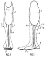
- FIGS. 1 to 5 represent a one-piece framework of prosthesis according to the invention, with a socket 1, intended to receive the stump of the amputee, a part of leg 2 adjoining the socket. 1 and coming from thermoforming therewith, and a prosthetic foot 3, adjoining the leg part 2 and coming from thermoforming therewith.
- This frame is intended to then receive a lining 4, for example in a flexible cellular material, imitating the shape of the member.
- the leg part 2 has two lateral ribs 5 and, at the rear, a rib 6 formed by the welding of the material used for thermoforming the frame, a polyolefin for example. Slot 1 has been cut into 7 in the usual way after thermoforming.
- the prosthetic leg 3 comprises a sole 8 of reinforcement made of carbon composite or any other elastic material, which is coated, at the front and at the rear, with the thermoforming material and whose purpose is to give a spring effect to the prosthetic foot during the walk of the amputee.
- a sole 8 of reinforcement made of carbon composite or any other elastic material which is coated, at the front and at the rear, with the thermoforming material and whose purpose is to give a spring effect to the prosthetic foot during the walk of the amputee.
- the upper front part of the prosthetic foot will advantageously be cut in 30, thus, possibly, that the part of the sole of the prosthetic foot disposed below this cutout 30.
- a wedge-shaped cutout 9 is provided at the prosthetic heel, between the sole and the leg part, in order to impart flexibility to the prosthesis which, at each step of the amputee , returns elastically to its starting position.
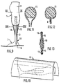
- the metal core 10, used to make the prosthesis according to the invention by molding or thermoforming, is shown in FIGS. 6,7 and 8.
- the reinforcing sole 8 Before molding, the reinforcing sole 8 is fixed under the base part of the core 10. If it is desired to simultaneously produce the socket 1, the head of the core 10 is drowned in a plaster reproduction 11 of the stump of the amputee 1. In order to reinforce by ribs 15, directed forwards and backwards, the part of the framework of the prosthesis which joins the leg part to the socket, two metal wires will be stretched obliquely 12 between the base of the plaster molding 11 of the stump and the core 10 (FIG. 9).
- the prosthesis framework will then be thermoformed under vacuum, for example by wrapping the core 10 thus equipped with a sheet of polyethylene 13 or other thermoplastic material (FIG. 10), by heating the sheet 13 so that it softens (FIG. 11) and by putting it under vacuum so that it is applied tightly against the core 10, the sole 8, the molding 11 and the metal wires 12 ( Figures 12 and 13), thus giving rise to the weld 6, which forms a rear rib ( Figure 12), and two side ribs 15 of reinforcement ( Figure 13).
- the sole 8 of carbon composite and its polyethylene sheath are cut at the base of the core 10, to allow the extraction of the latter, and the plaster molding 11 is destroyed to release the socket 1, which is then cut to the desired shape.
- leg portion 2 can have a cross section of any shape.
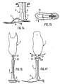
- the prosthetic foot 3 of the prosthesis frame can be fitted with a metal spring blade, in order to have an increased energy recovery effect during the walking of the amputee.
- FIGS. 14 and 15 are to be compared with FIGS. 3 and 5. It can be seen that a leaf spring 16 has been introduced into the foot through the opening made for the extraction of the thermoforming core, and that the blade 16 is bent between the front and rear ends of the prosthetic foot, against which it comes to brace, thereby giving this foot increased flexibility.
- FIGS 16 and 17 illustrate another embodiment of the prosthesis according to the invention. It can be seen in these drawings, where the members already described are designated by the same reference numbers, that the socket 10 is attached to the thermoformed one-piece body of the leg part 2 and of the prosthetic foot 3.
- a flattened projecting part 20 is provided at the upper end of the leg part 2, while a part 21 with a U-section, formed at the base of the socket 1, can cover this part 20.
- Holes 22, drilled in part 21, and an elongated lumen 23, formed in part 20, make it possible to assemble the socket 1 and the leg part 2 in a plurality of positions, according to a curve whose center and radius correspond to those of the knee joint, for example using screws and nuts.
- the invention therefore provides a monobloc prosthesis frame for a leg amputee, which can be manufactured by means known in the art, and which nonetheless provides appreciable technical progress for the amputee.
Landscapes
- Health & Medical Sciences (AREA)
- Transplantation (AREA)
- Biomedical Technology (AREA)
- Cardiology (AREA)
- Oral & Maxillofacial Surgery (AREA)
- Engineering & Computer Science (AREA)
- Orthopedic Medicine & Surgery (AREA)
- Heart & Thoracic Surgery (AREA)
- Vascular Medicine (AREA)
- Life Sciences & Earth Sciences (AREA)
- Animal Behavior & Ethology (AREA)
- General Health & Medical Sciences (AREA)
- Public Health (AREA)
- Veterinary Medicine (AREA)
- Prostheses (AREA)
Description
- La présente invention concerne une prothèse à ossature monobloc pour amputation de la jambe. L'invention concerne également un procédé de fabrication d'une telle prothèse.
- Les prothèses usuelles pour amputation de la jambe comprennent généralement trois éléments principaux :
- une partie formant fourreau, dite emboîture, dans laquelle vient se loger le moignon de la personne amputée et qui peut être rendue solidaire de ce moignon;
- un pied prothétique;
- et une partie de jambe réunissant l'emboîture et le pied prothétique.
- Ces éléments sont réalisés de façon séparée et sont ensuite assemblés pour former la prothèse, (voir, par exemple FR-A-1 162 321 et WO-A-89/09036). Ils peuvent être constitués de différents matériaux, mais la prothèse résultante est en général lourde, en particulier en raison de la structure du pied prothétique, et celui-ci a souvent une médiocre résistance mécanique.
- De ce fait, ces prothèses conviennent mal aux personnes âgées, qui, d'une part, se déplacent très peu et n'ont donc pas besoin d'une prothèse complexe, et qui, d'autre part, se fatiguent très rapidement, si la prothèse est trop lourde.
- US-A-3 909 855 décrit une prothèse monobloc du type "au-dessous du genou", dans laquelle une partie de jambe et une partie de pied forment un ensemble monobloc moulé. La partie de pied est cependant rigide et ne permet aucune souplesse par rapport à la partie de jambe.
- La présente invention vise à remédier à ces inconvénients en proposant une prothèse pour amputation de la jambe qui soit beaucoup plus légère et d'une structure plus simple que celles des techniques classiques et qui convienne ainsi particulièrement bien à une utilisation par des personnes âgées.
- L'invention a également pour but de proposer une prothèse de ce type qui puisse être réalisée sous forme monobloc par un procédé facile à mettre en oeuvre.
- Un autre but de l'invention est de proposer une prothèse du type ci-dessus, dont le pied prothétique présente une grande souplesse à la marche, en lui offrant un effet de restitution d'énergie. L'invention a enfin pour but de proposer une telle prothèse qui soit d'un coût de fabrication réduit.
- A cet effet, l'invention a pour objet une prothèse pour amputé de la jambe comprenant une ossature thermoformée en une matière thermoplastique ou en un matériau stratifié, gainée d'une matière de revêtement et comprenant une emboîture, une partie de jambe et un pied prothétique attenants deux à deux, l'ossature de la partie de jambe et du pied prothétique constituant un ensemble monobloc, venu d'une unique opération de moulage, cette prothèse étant caractérisée et en ce que le pied prothétique comprend, au niveau de la semelle, une découpe ayant servi à l'extraction du noyau de moulage et, au niveau du talon, au-dessus de la semelle, une découpe en forme de coin se prêtant à une flexion de l'arrière de la semelle par rapport à la partie de jambe.
- De préférence, l'emboîture sera également venue de moulage avec la partie de jambe et le pied prothétique, mais elle pourra aussi être rapportée sur celles-ci et comporter par exemple une partie saillante à section en U à sa partie inférieure, apte à coiffer une partie saillante de profil complémentaire ménagée à la partie supérieure de la partie de jambe et destinée à être fixée sur celle-ci dans la position la plus appropriée à l'aide de vis et d'écrous.
- L'invention a également pour objet un procédé de fabrication d'une telle prothèse, selon lequel on moule en une matière thermoplastique ou en un matériau stratifié une ossature monobloc de la partie de jambe et du pied prothétique autour d'un noyau approprié, caractérisé en ce qu'après moulage, on découpe la semelle du pied prothétique pour extraire le noyau, et en ce que l'on ménage dans l'ossature moulée, au niveau du talon du pied prothétique et au-dessus de la semelle, une découpe en forme de coin se prêtant à une flexion de l'arrière de la semelle par rapport à la partie de jambe.
- Avantageusement, une semelle de renfort en un matériau apte à se déformer élastiquement, en composite de carbone et de verre ou tout autre matériau apte à la déformation élastique, par exemple, sera incorporée dans le pied prothétique. Cette semelle pourra être fixée au-dessous du noyau utilisé pour le moulage, préalablement à la réalisation de l'ossature monobloc de la prothèse.
- Dans le but d'accroître les effets de restitution d'énergie à la prothèse, au cours de la marche, une lame ressort métallique pourra aussi être incorporée dans le pied prothétique au-dessus de la semelle en un matériau déformable élastiquement, en étant recourbée entre la partie avant et la partie arrière de la semelle.
- Lorsque l'emboîture sera réalisée en même temps que la partie de jambe et le pied prothétique, également par moulage, une forme en plâtre reproduisant la forme du moignon sera fixée en position correspondante sur le noyau utilisé pour le moulage.
- Avantageusement, à l'avant et à l'arrière de la partie de jambe seront ménagées des nervures, que l'on réalisera facilement, comme on l'exposera ci-après, en tendant obliquement un fil métallique entre la base de l'emboîture et la partie de jambe, à l'avant et à l'arrière de celle-ci.
- D'autres caractéristiques et avantages de l'invention apparaîtront dans la description détaillée qui va suivre de diverses formes de réalisation, données à titre d'exemple non limitatif. Dans cette description, on se réfèrera aux dessins schématiques annexés, sur lesquels :
- Les figures 1 et 2 sont des vues, respectivement en élévation latérale et de l'arrière d'une ossature monobloc de prothèse selon l'invention, avec le profil de la prothèse représenté en traits interrompus ;
- La figure 3 est une vue à plus grande échelle de la partie inférieure de la figure 1 ;
- La figure 4 est une vue suivant la flèche F₄ de la figure 3;
- La figure 5 est une coupe avec arrachement partiel suivant la ligne V-V de la figure 3;
- Les figures 6,7 et 8 sont des vues, respectivement, en élévation latérale, de face, et de dessus du noyau métallique utilisé pour effectuer le moulage de l'ossature de prothèse conforme à l'invention ;
- La figure 9 est une vue analogue à la figure 8, dans le cas de la réalisation d'une ossature de prothèse avec l'emboîture attenante ;
- La figure 10 illustre un exemple de thermoformage sous vide appliqué au noyau de la figure 9 ;
- Les figures 11 et 12 sont des coupes transversales à plus grande échelle, illustrant deux phases du thermoformage de l'ossature au niveau de la ligne XI-XI de la figure 9 ;
- La figure 13 est une coupe transversale, illustrant le thermoformage au niveau de la ligne XIII-XIII de la figure 9;
- Les figures 14 et 15 sont des vues analogues respectivement, aux figures 3 et 5, d'une variante de l'ossature de prothèse conforme à l'invention dans laquelle une lame ressort recourbée est insérée dans le pied prothétique;
- Les figures 16 et 17 sont des vues, respectivement en élévation latérale et de l'arrière, d'une autre variante de la prothèse selon l'invention, où l'emboîture est rapportée sur l'ossature thermoformée.
- On se réfèrera d'abord aux figures 1 à 5, qui représentent une ossature monobloc de prothèse conforme à l'invention, avec une emboîture 1, destinée à recevoir le moignon de la personne amputée, une partie de jambe 2 attenante à l'emboîture 1 et venue de thermoformage avec celle-ci, et un pied prothétique 3, attenant à la partie de jambe 2 et venu de thermoformage avec celle-ci. Cette ossature est destinée à recevoir ensuite une garniture 4, par exemple en une matière cellulaire souple, imitant la forme du membre.
- La partie de jambe 2 présente deux nervures latérales 5 et, à l'arrière, une nervure 6 formée par la soudure du matériau utilisé pour le thermoformage de l'ossature, une polyoléfine par exemple. L'emboîture 1 a été échancrée en 7 de façon usuelle après thermoformage.
- Comme on le voit plus clairement sur les figures 3, 4 et 5, le pied prothétique 3 comporte une semelle 8 de renforcement en composite de carbone ou tout autre matériau élastique, qui est enrobée, à l'avant et à l'arrière, du matériau de thermoformage et dont le but est de donner un effet de ressort au pied prothétique au cours de la marche de la personne amputée. On peut utiliser des semelles 8 différentes, suivant le poids et l'activité de la personne amputée, afin de moduler l'effet de ressort désiré. Pour conférer de la souplesse à la semelle thermoformée du pied prothétique et à la semelle 8, la partie supérieure avant du pied prothétique sera avantageusement découpée en 30, ainsi, éventuellement, que la partie de la semelle du pied prothétique disposée au-dessous de cette découpe 30. Dans le même but, une découpe 9 en forme de coin est ménagée au niveau du talon prothétique, entre la semelle et la partie de jambe, afin de conférer de la souplesse à la prothèse qui, à chaque pas de l'amputé, revient élastiquement à sa position de départ.
- Le noyau métallique 10, servant à réaliser par moulage ou par thermoformage la prothèse conforme à l'invention, est représenté sur les figures 6,7 et 8.
- Avant de procéder au moulage, on fixe la semelle de renfort 8 sous la partie de base du noyau 10. Si l'on désire réaliser simultanément l'emboîture 1, on noie la tête du noyau 10 dans une reproduction en plâtre 11 du moignon de l'amputé 1. Afin de renforcer par des nervures 15, dirigées vers l'avant et vers l'arrière, la partie de l'ossature de la prothèse qui réunit la partie de jambe à l'emboîture, on tendra obliquement deux fils métalliques 12 entre la base du moulage en plâtre 11 du moignon et le noyau 10 (figure 9).
- On procédera ensuite et par exemple de façon usuelle au thermoformage sous vide de l'ossature de prothèse, en enveloppant d'une feuille de polyéthylène 13 ou d'un autre matériau thermoplastique le noyau 10 ainsi équipé (figure 10), en chauffant la feuille 13 de manière qu'elle ramollisse (figure 11) et en la mettant sous dépression pour qu'elle s'applique étroitement contre le noyau 10, la semelle 8, le moulage 11 et les fils métalliques 12 (figures 12 et 13), en donnant ainsi naissance à la soudure 6, qui forme une nervure postérieure (figure 12), et à deux nervures latérales 15 de renfort (figure 13).
- Après thermoformage de la prothèse, la semelle 8 de composite de carbone et sa gaine de polyéthylène sont découpées à la base du noyau 10, pour permettre l'extraction de celui-ci, et le moulage de plâtre 11 est détruit pour dégager l'emboîture 1, qui est ensuite découpée à la forme voulue.
- On notera que la partie de jambe 2 peut avoir une section transversale de forme absolument quelconque.
- Ainsi qu'il a été indiqué ci-dessus, on peut équiper d'une lame de ressort métallique le pied prothétique 3 de l'ossature de prothèse, afin d'avoir un effet accru de récupération d'énergie au cours de la marche de l'amputé.
- C'est ce qui est représenté sur les figures 14 et 15, qui sont à rapprocher des figures 3 et 5. On voit qu'une lame de ressort 16 a été introduite dans le pied à travers l'ouverture ménagée pour l'extraction du noyau de thermoformage, et que la lame 16 est recourbée entre les extrémités avant et arrière du pied prothétique, contre lesquelles elle vient s'arc-bouter, en donnant ainsi à ce pied une souplesse accrue.
- Enfin, les figures 16 et 17 illustrent une autre forme de réalisation de la prothèse conforme à l'invention. On voit, sur ces dessins, où les organes déjà décrits sont désignés par les mêmes chiffres de référence, que l'emboîture 10 est rapportée sur le corps monobloc thermoformé de la partie de jambe 2 et du pied prothétique 3.
- Dans ce but, une partie saillante aplatie 20 est prévue à l'extrémité supérieure de la partie de jambe 2, tandis qu'une partie 21 à section en U, ménagée à la base de l'emboîture 1, peut coiffer cette partie 20. Des trous 22, percés dans la partie 21, et une lumière allongée 23, ménagée dans la partie 20, permettent d'assembler l'emboîture 1 et la partie de jambe 2 en une pluralité de positions, selon une courbe dont le centre et le rayon correspondent à ceux de l'articulation du genou, par exemple à l'aide de vis et d'écrous.
- L'invention apporte donc une ossature monobloc de prothèse pour amputé de la jambe, qui peut être fabriquée par des moyens connus dans la technique, et qui n'en apporte pas moins un progrès technique appréciable pour l'amputé.
Claims (6)
- Prothèse pour amputé de la jambe comprenant une ossature thermoformée en une matière thermoplastique ou en un matériau stratifié, gainée d'une matière de revêtement et comprenant une emboîture (1), une partie de jambe (2) et un pied prothétique (3) attenants deux à deux, l'ossature de la partie de jambe (2) et du pied prothétique (3) constituant un ensemble monobloc, venu d'une unique opération de moulage, cette prothèse étant caractérisée en ce que le pied prothétique comprend, au niveau de la semelle, une découpe (30) ayant servi à l'extraction du noyau de moulage et, au niveau du talon, au-dessus de la semelle, une découpe (9) en forme de coin se prêtant à une flexion de l'arrière de la semelle par rapport à la partie de jambe.
- Prothèse selon la revendication 1, caractérisée en ce que, dans le pied prothétique (3), est incorporée une semelle (8) en un matériau déformable élastiquement.
- Prothèse selon la revendication 2, caractérisée en ce que, dans le pied prothétique 3, au-dessus de la semelle (8) en un matériau déformable élastiquement, est incorporée une lame ressort métallique (16), renflée en sa partie centrale et prenant appui par ses extrémités contre l'extrémité avant et l'extrémité arrière de la semelle du pied prothétique (3).
- Procédé de fabrication d'une prothèse selon la revendication 1, selon lequel on moule en une matière thermoplastique ou en un matériau stratifié une ossature monobloc de la partie de jambe (2) et du pied prothétique (3) de la prothèse, autour d'un noyau (10) approprié, caractérisé en ce qu'après moulage, on découpe la semelle du pied prothétique pour extraire le noyau (10), et en ce que l'on ménage dans l'ossature moulée, au niveau du talon du pied prothétique et au-dessus de la semelle, une découpe (9) en forme de coin se prêtant à une flexion de l'arrière de la semelle par rapport à la partie de jambe.
- Procédé selon la revendication 4, caractérisé en ce que, préalablement au moulage de la matière thermoplastique ou du matériau stratifié, on fixe sous le noyau (10) utilisé pour le thermoformage une semelle de renfort (8) en un matériau élastiquement déformable, de façon telle qu'elle soit rendue solidaire de ce matériau au cours de l'opération de thermoformage, et en ce que, après cette opération, on extrait le noyau (10) à travers une ouverture ménagée dans cette semelle et dans le matériau de thermoformage.
- Procédé selon la revendication 5, caractérisé en ce que, après l'extraction du noyau (10), on introduit dans le pied prothétique une lame ressort métallique ou en un autre matériau déformable élastiquement arc-boutée et recourbée entre l'extrémité avant et l'extrémité arrière du pied prothétique.
Applications Claiming Priority (2)
| Application Number | Priority Date | Filing Date | Title |
|---|---|---|---|
| FR9005126 | 1990-04-23 | ||
| FR9005126A FR2661087B1 (fr) | 1990-04-23 | 1990-04-23 | Prothese a ossature monobloc pour amputation de la jambe et procede de fabrication de cette prothese. |
Publications (2)
| Publication Number | Publication Date |
|---|---|
| EP0454524A1 EP0454524A1 (fr) | 1991-10-30 |
| EP0454524B1 true EP0454524B1 (fr) | 1994-07-20 |
Family
ID=9395978
Family Applications (1)
| Application Number | Title | Priority Date | Filing Date |
|---|---|---|---|
| EP91400940A Expired - Lifetime EP0454524B1 (fr) | 1990-04-23 | 1991-04-08 | Prothèse de jambe à ossature monobloc et son procédé de fabrication |
Country Status (5)
| Country | Link |
|---|---|
| US (1) | US5116381A (fr) |
| EP (1) | EP0454524B1 (fr) |
| DE (1) | DE69102935T2 (fr) |
| ES (1) | ES2056597T3 (fr) |
| FR (1) | FR2661087B1 (fr) |
Families Citing this family (28)
| Publication number | Priority date | Publication date | Assignee | Title |
|---|---|---|---|---|
| US5181932A (en) * | 1989-04-13 | 1993-01-26 | Phillips L Van | Foot prosthesis having auxiliary ankle construction |
| US5766265A (en) * | 1985-08-01 | 1998-06-16 | Phillips; Van L. | Prosthetic foot having curved integral support |
| US5387246A (en) * | 1989-04-13 | 1995-02-07 | Phillips; Van L. | Prosthetic ski leg |
| US5290319A (en) | 1991-02-28 | 1994-03-01 | Phillips L Van | Prosthetic foot incorporating adjustable bladders |
| US5514186A (en) * | 1989-04-13 | 1996-05-07 | Phillips; Van L. | Attachment construction for prosthesis |
| US6406500B1 (en) | 1989-04-13 | 2002-06-18 | Van L. Phillips | Foot prosthesis having curved forefoot |
| US5217500A (en) * | 1990-01-12 | 1993-06-08 | Phillips L Van | Prosthetic leg |
| US5549714A (en) | 1990-09-21 | 1996-08-27 | Phillips; Van L. | Symes foot prosthesis |
| US5181933A (en) | 1991-02-28 | 1993-01-26 | Phillips L Van | Split foot prosthesis |
| US5376127A (en) * | 1991-07-01 | 1994-12-27 | Swanson; Vern M. | Prosthesis cover and method of producing |
| US5219364A (en) * | 1991-09-12 | 1993-06-15 | Wright & Filippis, Inc. | Continuous one-piece prosthesis |
| AU658687B2 (en) * | 1991-09-30 | 1995-04-27 | Van L. Phillips | Energy-storing prosthetic leg pylon |
| US5653767A (en) * | 1992-11-17 | 1997-08-05 | Medonics, Llc | Prosthetic foot |
| WO1994010943A1 (fr) * | 1992-11-17 | 1994-05-26 | Allen Scott E | Prothese de pied a ressort enroule |
| US5443528A (en) * | 1992-11-17 | 1995-08-22 | Allen; Scott | Coil spring prosthetic foot |
| US5653768A (en) * | 1994-01-21 | 1997-08-05 | Bruce Kania | Dual cantilevered leaf spring structure |
| US5993487A (en) * | 1994-12-29 | 1999-11-30 | Wright & Filippis | Integrated keel-pylon prosthesis |
| GB9516993D0 (en) * | 1995-08-18 | 1995-10-18 | Blatchford & Sons Ltd | An artificial limb |
| US5800570A (en) * | 1996-03-14 | 1998-09-01 | Collier; Milo S. | Lower extremity prosthetic device |
| GB9724680D0 (en) * | 1997-11-21 | 1998-01-21 | Blatchford & Sons Ltd | A foot and shin component for a lower limb prosthesis |
| US6206703B1 (en) * | 1999-03-01 | 2001-03-27 | Lear Corporation | Biofidelic human seating surrogate apparatus |
| US6131436A (en) * | 1999-03-01 | 2000-10-17 | Lear Corporation | Method and system for wear testing a seat by simulating human seating activity and robotic human body simulator for use therein |
| US6220089B1 (en) | 1999-03-01 | 2001-04-24 | Lear Corporation | Vibration dummy apparatus |
| RU2162673C2 (ru) * | 1999-05-17 | 2001-02-10 | Открытое акционерное общество "Ракетно-космическая корпорация "Энергия" им. С.П. Королева" | Протез голени |
| US6811571B1 (en) * | 2000-05-02 | 2004-11-02 | Van L. Phillips | Universal prosthesis with cushioned ankle |
| US7108723B2 (en) * | 2000-12-22 | 2006-09-19 | Townsend Barry W | Prosthetic foot |
| US6443995B1 (en) | 2000-12-22 | 2002-09-03 | Barry W. Townsend | Prosthetic foot |
| JP4195611B2 (ja) * | 2000-12-22 | 2008-12-10 | ダブリュ タウンゼンド、バリー | 人工足 |
Family Cites Families (12)
| Publication number | Priority date | Publication date | Assignee | Title |
|---|---|---|---|---|
| DE405686C (de) * | 1924-11-08 | Arthur Rudow Dr | Gummifuss mit eingebettetem Holzkern | |
| US470431A (en) * | 1892-03-08 | George e | ||
| FR690657A (fr) * | 1930-02-25 | 1930-09-24 | Perfectionnements aux jambes artificielles | |
| US2379538A (en) * | 1942-09-09 | 1945-07-03 | Meierhofer Max | Joint for leg supports and artificial limbs in general |
| FR1162321A (fr) * | 1956-11-12 | 1958-09-11 | Appareil de prothèse en matière plastique armée, et procédé de fabrication | |
| US3909855A (en) * | 1974-11-12 | 1975-10-07 | Joseph G Barredo | Below-the-knee prosthesis |
| SU806026A1 (ru) * | 1979-01-30 | 1981-02-23 | Центральный Ордена Трудового Красногознамени Научно-Исследовательскийинститут Протезирования И Проте-Зостроения | Способ изготовлени косметической об-лицОВКи пРОТЕзА НижНиХ КОНЕчНОСТЕй |
| US4822363A (en) * | 1985-08-01 | 1989-04-18 | Phillips L Van | Modular composite prosthetic foot and leg |
| AU3424489A (en) * | 1988-03-31 | 1989-10-16 | Sabolich, Inc. | Prosthetic foot |
| US4959073A (en) * | 1988-06-06 | 1990-09-25 | John Merlette | Foot prosthesis and method of making same |
| US4911724A (en) * | 1988-07-26 | 1990-03-27 | J&J Orthotics Inc. | Energy responsive prosthetic leg |
| FR2638087B1 (fr) * | 1988-10-21 | 1997-04-30 | Proteor Sa | Prothese pour amputation de jambe et son procede de fabrication |
-
1990
- 1990-04-23 FR FR9005126A patent/FR2661087B1/fr not_active Expired - Lifetime
-
1991
- 1991-04-08 EP EP91400940A patent/EP0454524B1/fr not_active Expired - Lifetime
- 1991-04-08 ES ES91400940T patent/ES2056597T3/es not_active Expired - Lifetime
- 1991-04-08 DE DE69102935T patent/DE69102935T2/de not_active Expired - Fee Related
- 1991-04-23 US US07/690,051 patent/US5116381A/en not_active Expired - Fee Related
Also Published As
| Publication number | Publication date |
|---|---|
| DE69102935D1 (de) | 1994-08-25 |
| EP0454524A1 (fr) | 1991-10-30 |
| US5116381A (en) | 1992-05-26 |
| FR2661087A1 (fr) | 1991-10-25 |
| ES2056597T3 (es) | 1994-10-01 |
| DE69102935T2 (de) | 1994-12-15 |
| FR2661087B1 (fr) | 1992-08-14 |
Similar Documents
| Publication | Publication Date | Title |
|---|---|---|
| EP0454524B1 (fr) | Prothèse de jambe à ossature monobloc et son procédé de fabrication | |
| CA2338176C (fr) | Semelle de chaussure | |
| EP0625033A1 (fr) | Prothese de pied | |
| EP0798021B1 (fr) | Planche de ski entourée d'une carre continue | |
| FR2745488A1 (fr) | Prothese reactive de pied | |
| FR2638087A1 (fr) | Prothese pour amputation de jambe et son procede de fabrication | |
| FR2681515A1 (fr) | Semelage a protuberances pour chaussures de sport. | |
| FR2575049A1 (fr) | Sac a dos | |
| EP0677252A1 (fr) | Chaussure de ski en matière plastique | |
| WO1999030649A1 (fr) | Prothese totale de genou a plateau tibial mobile en rotation | |
| FR2734151A1 (fr) | Structure reactive de pied prothetique | |
| EP0674887A1 (fr) | Perfectionnement aux prothèses de genou | |
| FR2524307A1 (fr) | Lentille intraoculaire a boucles de support asymetriques | |
| FR2559072A1 (fr) | Jouet changeant d'etat | |
| FR2768938A1 (fr) | Raquette a neige | |
| FR2542983A1 (fr) | Ensemble compose d'une poche d'air, d'une pompe et d'une soupape, destine a etre incorpore a des chaussures, notamment des chaussures de ski | |
| EP1112045B1 (fr) | Implant intra-oculaire de chambre anterieure | |
| EP1295540B1 (fr) | Chaussure de ski alpin | |
| EP0504769B1 (fr) | Chaussure de ski alpin à volet d'énergie articulé sur le bas de coque | |
| CH645787A5 (fr) | Chaussure de ski. | |
| FR2698538A1 (fr) | Nouvelle structure de pied prothétique à restitution d'énergie. | |
| FR2484800A1 (fr) | Dispositif de flexion pour chaussure de ski | |
| FR2736276A1 (fr) | Dispositif pour produire la fermeture de l'un ou des deux yeux d'une poupee | |
| FR2601862A1 (fr) | Chaussure de ski | |
| EP0968669B1 (fr) | Bracelet formé par une structure souple et par une pluralité d'éléments durs et procédé d'assemblage d'un tel bracelet |
Legal Events
| Date | Code | Title | Description |
|---|---|---|---|
| PUAI | Public reference made under article 153(3) epc to a published international application that has entered the european phase |
Free format text: ORIGINAL CODE: 0009012 |
|
| AK | Designated contracting states |
Kind code of ref document: A1 Designated state(s): BE DE ES GB IT NL SE |
|
| 17P | Request for examination filed |
Effective date: 19911025 |
|
| 17Q | First examination report despatched |
Effective date: 19930430 |
|
| GRAA | (expected) grant |
Free format text: ORIGINAL CODE: 0009210 |
|
| AK | Designated contracting states |
Kind code of ref document: B1 Designated state(s): BE DE ES GB IT NL SE |
|
| REF | Corresponds to: |
Ref document number: 69102935 Country of ref document: DE Date of ref document: 19940825 |
|
| GBT | Gb: translation of ep patent filed (gb section 77(6)(a)/1977) |
Effective date: 19940815 |
|
| REG | Reference to a national code |
Ref country code: ES Ref legal event code: FG2A Ref document number: 2056597 Country of ref document: ES Kind code of ref document: T3 |
|
| ITF | It: translation for a ep patent filed | ||
| EAL | Se: european patent in force in sweden |
Ref document number: 91400940.2 |
|
| PLBE | No opposition filed within time limit |
Free format text: ORIGINAL CODE: 0009261 |
|
| STAA | Information on the status of an ep patent application or granted ep patent |
Free format text: STATUS: NO OPPOSITION FILED WITHIN TIME LIMIT |
|
| 26N | No opposition filed | ||
| REG | Reference to a national code |
Ref country code: GB Ref legal event code: IF02 |
|
| PGFP | Annual fee paid to national office [announced via postgrant information from national office to epo] |
Ref country code: GB Payment date: 20030415 Year of fee payment: 13 |
|
| PGFP | Annual fee paid to national office [announced via postgrant information from national office to epo] |
Ref country code: SE Payment date: 20030417 Year of fee payment: 13 |
|
| PGFP | Annual fee paid to national office [announced via postgrant information from national office to epo] |
Ref country code: ES Payment date: 20030422 Year of fee payment: 13 |
|
| PGFP | Annual fee paid to national office [announced via postgrant information from national office to epo] |
Ref country code: NL Payment date: 20030423 Year of fee payment: 13 Ref country code: DE Payment date: 20030423 Year of fee payment: 13 |
|
| PGFP | Annual fee paid to national office [announced via postgrant information from national office to epo] |
Ref country code: BE Payment date: 20030512 Year of fee payment: 13 |
|
| PG25 | Lapsed in a contracting state [announced via postgrant information from national office to epo] |
Ref country code: GB Free format text: LAPSE BECAUSE OF NON-PAYMENT OF DUE FEES Effective date: 20040408 |
|
| PG25 | Lapsed in a contracting state [announced via postgrant information from national office to epo] |
Ref country code: SE Free format text: LAPSE BECAUSE OF NON-PAYMENT OF DUE FEES Effective date: 20040409 |
|
| PG25 | Lapsed in a contracting state [announced via postgrant information from national office to epo] |
Ref country code: ES Free format text: LAPSE BECAUSE OF NON-PAYMENT OF DUE FEES Effective date: 20040410 |
|
| PG25 | Lapsed in a contracting state [announced via postgrant information from national office to epo] |
Ref country code: BE Free format text: LAPSE BECAUSE OF NON-PAYMENT OF DUE FEES Effective date: 20040430 |
|
| BERE | Be: lapsed |
Owner name: ETS *PROTEOR Effective date: 20040430 |
|
| PG25 | Lapsed in a contracting state [announced via postgrant information from national office to epo] |
Ref country code: NL Free format text: LAPSE BECAUSE OF NON-PAYMENT OF DUE FEES Effective date: 20041101 |
|
| PG25 | Lapsed in a contracting state [announced via postgrant information from national office to epo] |
Ref country code: DE Free format text: LAPSE BECAUSE OF NON-PAYMENT OF DUE FEES Effective date: 20041103 |
|
| EUG | Se: european patent has lapsed | ||
| GBPC | Gb: european patent ceased through non-payment of renewal fee |
Effective date: 20040408 |
|
| NLV4 | Nl: lapsed or anulled due to non-payment of the annual fee |
Effective date: 20041101 |
|
| PG25 | Lapsed in a contracting state [announced via postgrant information from national office to epo] |
Ref country code: IT Free format text: LAPSE BECAUSE OF NON-PAYMENT OF DUE FEES Effective date: 20050408 |
|
| REG | Reference to a national code |
Ref country code: ES Ref legal event code: FD2A Effective date: 20040410 |