EP0454555B1 - Blasrampe - Google Patents
Blasrampe Download PDFInfo
- Publication number
- EP0454555B1 EP0454555B1 EP91401057A EP91401057A EP0454555B1 EP 0454555 B1 EP0454555 B1 EP 0454555B1 EP 91401057 A EP91401057 A EP 91401057A EP 91401057 A EP91401057 A EP 91401057A EP 0454555 B1 EP0454555 B1 EP 0454555B1
- Authority
- EP
- European Patent Office
- Prior art keywords
- blowing
- air
- protected
- elements
- ultraclean
- Prior art date
- Legal status (The legal status is an assumption and is not a legal conclusion. Google has not performed a legal analysis and makes no representation as to the accuracy of the status listed.)
- Expired - Lifetime
Links
Images


Classifications
-
- H—ELECTRICITY
- H10—SEMICONDUCTOR DEVICES; ELECTRIC SOLID-STATE DEVICES NOT OTHERWISE PROVIDED FOR
- H10P—GENERIC PROCESSES OR APPARATUS FOR THE MANUFACTURE OR TREATMENT OF DEVICES COVERED BY CLASS H10
- H10P72/00—Handling or holding of wafers, substrates or devices during manufacture or treatment thereof
- H10P72/30—Handling or holding of wafers, substrates or devices during manufacture or treatment thereof for conveying, e.g. between different workstations
- H10P72/36—Handling or holding of wafers, substrates or devices during manufacture or treatment thereof for conveying, e.g. between different workstations using air tracks
-
- B—PERFORMING OPERATIONS; TRANSPORTING
- B08—CLEANING
- B08B—CLEANING IN GENERAL; PREVENTION OF FOULING IN GENERAL
- B08B17/00—Methods preventing fouling
- B08B17/02—Preventing deposition of fouling or of dust
-
- B—PERFORMING OPERATIONS; TRANSPORTING
- B08—CLEANING
- B08B—CLEANING IN GENERAL; PREVENTION OF FOULING IN GENERAL
- B08B5/00—Cleaning by methods involving the use of air flow or gas flow
- B08B5/02—Cleaning by the force of jets, e.g. blowing-out cavities
- B08B5/023—Cleaning travelling work
Definitions
- the invention relates to storage and more particularly the transport of parts including one surface must be maintained in an environment ultra clean. It particularly applies to protection against pollution or contamination ambient particulate of silicon wafers hanging their transport.
- the silicon wafers supporting these integrated circuits are stored in stations loading and unloading. We send them there by suitable means of transport, such as air cushions, belt conveyors, vacuum grippers. These trips are made between different treatment stations which can be a reactor, an oven or an insulator. The slices can then be stored again. The different treatment stations are subject to an ultra clean and non-polluting environment for the silicon wafers. However, a dust contamination is still possible during transport, if it does not benefit special environmental precautions.
- This corridor includes a first type of horizontal unit elements made up of individual conduits with nozzles and a system hanging. Two side skirts in soft material and airtight are constituted by a second type vertical unit elements. Horizontal ducts being connected to a source of pressurized air, the nozzles project this air inside the corridor formed by the horizontal unitary ducts and the lateral elements forming the skirt. These elements are assembled together. others so as to adapt to the geometry of the course to protect. This corridor is for protection against the pollution of silicon wafers during their transport. This type of corridor can be effective in now an ultra clean environment but by putting in play of large air flows.
- IBM TECHNICAL DISCLOSURE BULLETIN volume 22, No. 5, October 1979, pages 1 864 and 1 865, describes a semiconductor wafer gripping system. This device avoids the introduction of particles contaminated on semiconductor wafers.
- flow the air supplied cannot be laminar.
- US-A-4037830 describes a gripping device using laminar flow.
- IBM TECHNICAL DISCLOSURE BULLETIN volume 17, n ° 10, of March 1975, page 2904, describes a corridor for semiconductor wafers using a laminar flow.
- the object of the invention is to provide means of protection of the silicon wafers during their transport using the air blowing technique under pressure, but avoiding the above-mentioned drawback.
- the main object of the invention is a fan ramp for surface protection of objects against ambient particulate contamination by confinement in an atmosphere of ultra clean air by means of blowers distributing the air ultra clean through air distribution ports opening out through a blowing surface into a space where objects to be contained must be placed.
- blowing elements are round and have a single central opening. They thus constitute a ramp fan adaptable to the path traveled by the objects carrying the surface to be protected, the various elements blowers being placed end to end, the ramp being thus suitable for confining the surfaces to be protected in ultra clean air by placing the surfaces to be protected a relatively short distance (d) from the surface blower, ultra clean air having a flow having a value between a minimum flow which is the flow for which air can still sweep all surfaces protect from the object and exit on the outskirts of these, and a maximum flow which is the right flow above which appears a turbulent air regime ultra clean, the flow of ultra clean air in the volume formed by the surfaces to be protected and the surface fan placed parallel opposite one of the other being thus laminar, at least at the periphery surfaces to protect.
- the fan ramp comprises at each end of the end elements comprising a transverse portion of pipe thus forming a transverse air curtain.
- Each pipe can be completed with a baffle placed next to supply conduits opening into the pipes, thus improving the distribution of ultra clean air throughout the pipeline.
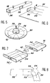
- the means of transport of flat objects, such as silicon wafers, shown on Figure 1 is a track 14 provided with conduits air jets 15 opening obliquely into the longitudinal direction, so as to advance the silicon wafer 10.
- This track 14 is positioned at the outlet of a cassette 12 in which are rows of several silicon wafers 10.
- Figure 2 shows one of the devices change of direction. It consists of placing near a runway 14 a suction gripper 21.
- the latter consists of a base block 16, fixed with respect to runway 14 and supporting a vertical rotating shaft 17.
- an articulated system 18 of the pantograph type of which a first vertex is fixed to the tree 17 and of which the second summit is equipped with a device suction.
- Full deployment of the pantograph 18 allows suction device 19 to come over from runway 14 to take a silicon wafer 10.
- the folding of the pantograph 18 makes it possible to bring the silicon wafer above the base block 16.
- the element shown in Figure 3 is a longitudinal blowing element, used to form a fan ramp. It consists of a plate plane 2 constituting a blowing ceiling. She owns orifices 6 opening onto its lower surface 7, which is therefore a blowing surface.
- Line 4 is fixed on the upper surface 5 of the plate 2, opposite the orifices 6.
- the pipe 4, shown in Figure 3 has a shape semi-cylindrical. This is just one example of achievement, the result necessary for the effectiveness of the method being that this pipe 4 supplies air the central openings 6.
- the supply of this line 4 in ultra clean air can be obtained at means of conduits 8 opening into this pipe 4.
- the openings 6 are generally formed a single longitudinal center slit.
- Figure 4 shows more precisely the position of the silicon wafer 10 relative to to the longitudinal element, marked 1 in this figure.
- the silicon wafer 10 is placed at a distance d which is of the order of a millimeter. More exactly, in the case of application to silicon wafers, this distance is usually between 0.5 and 3 mm.
- d the distance which is of the order of a millimeter. More exactly, in the case of application to silicon wafers, this distance is usually between 0.5 and 3 mm.
- this is placed symmetrically with respect to the orifices 6, so that the ultra clean air coming out of the orifices 6 of the blowing surface 7 is distributed so equal on both sides of the volume formed by the surface blower 7 and the upper surface to be protected 11 of the silicon wafer 10.
- Each line 4 can be completed inside a baffle, marked 9 in the figure 4. This is placed opposite the orifices supply 8 opening into the upper part of line 4.
- This baffle 9 is intended to lengthen the path of ultra clean air in line 4 to improve distribution of the latter throughout the volume of the pipeline 4. This has the effect of standardizing the air flow in the longitudinal slot 6.
- orifices 6 In order to obtain a laminar flow in this volume, i.e. a regular flow without turbulence and without an opposite air flow, orifices 6 have a particular shape.
- the holes 6 may consist of a longitudinal slot having preferably a V shape inside the pipe 4.
- the final spacing e of the longitudinal slot is preferably between 0.3 and 2 mm.
- the flow rate Q of ultra clean air is the one just below which appears a turbulent regime of ultra clean air.
- Plate 2 is also dimensioned in function of the diameter D of the silicon wafer 10. It is necessarily wider than the diameter D of the silicon wafer 10, this width preferably being equal to D x 6/5.
- the contamination of the transported slices under these elements is minimal for a flow of 2 to 3 m 3 / hm of the fan rail thus formed. It is therefore preferable in this case to have a flow rate of the order of 5 m 3 / h.
- the volume of air leaving one side of a silicon wafer is therefore equal to 0.375 m 3 / h, through an outlet section equal to D xd, i.e. 0.45 x 10 - 3 m 2 .
- the flow velocity V m is equal to 0.375 / 3600 x 1 / 0.45.10 -3 , that is to say approximately 0.23 m / s.
- the number of REYNOLDS R is therefore equal to V m xe / ⁇ equal to 23 x 3.10 -1 /15.10 -2 , i.e. about 50.
- Figure 5 shows a blowing element circular. Its structure and functioning are similar to those of a longitudinal blowing element. The fundamental differences with the element longitudinal are that the pipeline gets reduced to a simple hemispherical form 24. It is applied to a circular plate 25 above a central orifice 26. It is supplied by a conduit 28 connected to an ultra clean air source.
- Air flow through the orifice central 26 is done analogously to the flow obtained with a longitudinal blowing element, i.e. that this flow is symmetrical with respect in the center of the circular plate 25 and remains laminar.
- This figure shows a pipe 34 of rectangular shape. This is always supplied by connected conduits 8 to a source of ultra clean air under pressure.
- the longitudinal element 32 can, in the case where it constitutes the end of a ramp blower, be equipped with an end element 38 consisting of a transverse portion of pipeline connected to pipeline 34 by a lateral opening 39 placed in the middle of the line 38.
- the latter has so analogous to line 34 of the element longitudinal 32, a slot 36 similar to the slot described in Figures 3 and 4. Therefore, this pipeline also being supplied with air ultra clean, a transverse air curtain constitutes additional protection of silicon wafers vis-à-vis contamination.
- the different longitudinal blowers 32 can be assembled using clamping flanks 40. These last are placed transversely and vertically to plates 2, at each end thereof. These sidewalls can block the pipes if necessary 34.
- the longitudinal elements 32 are assembled by approximation by placing the flanks against each other transverse 40 placed at the respective ends of the longitudinal elements and keeping them that way glued by clamping and gluing.
- Figure 8 shows a top view of a ramp blower using first blowing elements longitudinal 32 and a circular blower 25 to change direction between two straight line portions.
- Other elements 33 are used to make the joint between the blowing elements longitudinal 32 and the round blowing element 25.
- These second longitudinal blowing elements 33 have one end in circular cutout, concave 35, complementary with the external shape of the round blower 25.
- Figure 9B is a top view corresponding to FIG. 9A.
- the crown area marked 46 corresponds to the area where the flow ultra-clean air is laminar.
- the air speed ultra-clean is almost nil in the center of the blowing element, when it leaves the duct 28.
- the flow velocity is increasing, as symbolize it radially oriented vectors in Figure 9B.
- the element blowing must have a larger diameter that the diameter D of the surface to be protected 11, in the occurrence a diameter equal to 6D / 5.
- the air flow and the distance d separating the two surfaces at their periphery also help to form a curtain protector with an efficiency equivalent to previously described achievements.
Landscapes
- Container, Conveyance, Adherence, Positioning, Of Wafer (AREA)
- Prevention Of Fouling (AREA)
Claims (3)
- Blasrampe zum Schutze der Oberflächen (1) von Gegenständen (10) gegen die Partikel-Verunreinigung aus der Umgebung durch Einschließung in eine Ultra-Reinluft-Atmosphäre mit Hilfe von Blaselementen (25, 32, 33, 38), die die Ultra-Reinluft durch Luftversorgungsöffnungen (6, 36) in einer Blasfläche (7) in einen Raum blasen, wo die einzuschließenden Gegenstände (10) angeordnet werden müssen,
dadurch gekennzeichnet, dass sie mehrere miteinander zusammengebaute Blaselemente umfasst, von denen jedes gebildet wird durch:weitere Blaselemente (25), die rund sind und eine zentrale Öffnung (26) haben und so eine Blasrampe bilden, die an den Weg angepasst werden kann, den die Gegenstände (10) mit den zu schützenden Oberflächen (11) durchlaufen, wobei die verschiedenen Blaselemente aneinandergefügt sind und die Rampe angepasst ist, um die zu schützenden Oberflächen (11) in Ultra-Reinluft einzuschließen, indem die zu schützenden Oberflächen (11) mit einem relativ kleinen Abstand (d) von der Blasfläche (7) angeordnet werden, und die Ultra-Reinluft einen Durchsatz mit einem Wert hat, der enthalten ist zwischen einem Mindestdurchsatz, der ausreicht, damit die Luft noch alle zu schützenden Oberflächen des Gegenstands (10) bestreichen und an deren Peripherie austreten kann, und einem Höchstdurchsatz, der direkt bzw. knapp unter dem Durchsatz liegt, bei dem ein turbulenter Zustand der Ultra-Reinluft eintreten würde, sodass also die Strömung der Ultra-Reinluft in dem Volumen, das die zu schützenden Oberflächen (11) und die zu ihr parallele Blasfläche (7) bilden, laminar ist, wenigstens an der Peripherie der zu schützenden Oberflächen.eine Platte (2, 22) mit einer Blasfläche (7), die wenigstens eine zentrale oder mittlere Öffnung (6, 26, 36) umfasst und eine Form aufweist, die wenigstens zu der der Peripherie der zu schützenden Oberflächen (11) komplementär ist;einen Kanal (4, 24, 34), an der Platte (2, 22) befestigt und in der Öffnung (6, 26, 36) mündend, der mit einer Ultra-Reinluft-Quelle verbunden werden kann, wobei die Öffnungen bestimmter Blaselemente (32, 33), die länglich sind, durch einen Längs-Mittelschlitz (36) gebildet werden; - Blasrampe nach Anspruch 1, dadurch gekennzeichnet, dass sie an jedem Ende Endelemente (38) umfasst, gebildet durch ein quer angeordnetes Kanalstück, das einen quergerichteten Luftvorhang liefert.
- Blasrampe nach einem der Ansprüche 1 oder 2, dadurch gekennzeichnet, dass jeder Kanal durch eine Schikane (9) vervollständigt wird, die den in die Kanäle (4, 24, 34) mündenden Versorgungsleitungen (8) gegenübersteht und für eine bessere Verteilung der Ultra-Reinluft im ganzen Kanal (4, 24, 34) sorgt.
Applications Claiming Priority (2)
| Application Number | Priority Date | Filing Date | Title |
|---|---|---|---|
| FR9005210 | 1990-04-24 | ||
| FR909005210A FR2661117B1 (fr) | 1990-04-24 | 1990-04-24 | Procede de protection de surfaces contre la contamination particulaire ambiante a l'aide d'elements soufflants. |
Publications (2)
| Publication Number | Publication Date |
|---|---|
| EP0454555A1 EP0454555A1 (de) | 1991-10-30 |
| EP0454555B1 true EP0454555B1 (de) | 2000-08-30 |
Family
ID=9396031
Family Applications (1)
| Application Number | Title | Priority Date | Filing Date |
|---|---|---|---|
| EP91401057A Expired - Lifetime EP0454555B1 (de) | 1990-04-24 | 1991-04-22 | Blasrampe |
Country Status (5)
| Country | Link |
|---|---|
| US (1) | US5241758A (de) |
| EP (1) | EP0454555B1 (de) |
| JP (1) | JPH04226011A (de) |
| DE (1) | DE69132386T2 (de) |
| FR (1) | FR2661117B1 (de) |
Families Citing this family (13)
| Publication number | Priority date | Publication date | Assignee | Title |
|---|---|---|---|---|
| US5439523A (en) * | 1994-02-14 | 1995-08-08 | Memc Electronic Materials, Inc. | Device for suppressing particle splash onto a semiconductor wafer |
| US6018842A (en) * | 1997-08-13 | 2000-02-01 | Billco Manufacturing, Inc. | Glass washing machine |
| US5934991A (en) * | 1998-02-01 | 1999-08-10 | Fortrend Engineering Corporation | Pod loader interface improved clean air system |
| NL1011487C2 (nl) * | 1999-03-08 | 2000-09-18 | Koninkl Philips Electronics Nv | Werkwijze en inrichting voor het roteren van een wafer. |
| NL1013989C2 (nl) | 1999-12-29 | 2001-07-02 | Asm Int | Werkwijze en inrichting voor het behandelen van een wafer. |
| US6883250B1 (en) | 2003-11-04 | 2005-04-26 | Asm America, Inc. | Non-contact cool-down station for wafers |
| JP2005262088A (ja) * | 2004-03-18 | 2005-09-29 | Fuji Photo Film Co Ltd | 支持体表面の防塵方法及び装置 |
| JP5678126B2 (ja) * | 2013-05-16 | 2015-02-25 | 川崎重工業株式会社 | 高い清浄度を要する板材加工装置 |
| JP5806702B2 (ja) * | 2013-05-16 | 2015-11-10 | 川崎重工業株式会社 | クリーン機能を備えた板材切断装置 |
| CN107685047A (zh) * | 2016-08-04 | 2018-02-13 | 特铨股份有限公司 | 非接触式光罩或晶圆洁净装置 |
| WO2019236695A1 (en) * | 2018-06-05 | 2019-12-12 | Illinois Tool Works Inc. | Air rinsing apparatus and systems for rinsing containers |
| CN109529980B (zh) * | 2018-11-16 | 2021-11-02 | 成都斯力康科技股份有限公司 | 适用于硅料入炉前的上游处理系统 |
| CN112354921A (zh) * | 2020-10-22 | 2021-02-12 | 刘应国 | 一种海洋监控设备的维护清理装置 |
Citations (3)
| Publication number | Priority date | Publication date | Assignee | Title |
|---|---|---|---|---|
| US3438668A (en) * | 1965-08-26 | 1969-04-15 | Gen Electric | Contactless lifter |
| US4037830A (en) * | 1976-09-07 | 1977-07-26 | International Business Machines Corporation | Wafer handler |
| WO1989012907A1 (en) * | 1988-06-17 | 1989-12-28 | Epsilon Technology, Inc. | Wafer handling system with bernoulli pick-up |
Family Cites Families (3)
| Publication number | Priority date | Publication date | Assignee | Title |
|---|---|---|---|---|
| US4236851A (en) * | 1978-01-05 | 1980-12-02 | Kasper Instruments, Inc. | Disc handling system and method |
| EP0224034A1 (de) * | 1985-10-29 | 1987-06-03 | Präzisions-Werkzeuge AG | Verfahren und Anordnung zur Verhinderung der Absenkung von Schwebepartikeln und thermische Behandlungsstation an einer Durchlauf-Innenbeschichtungsanlage |
| FR2632617B1 (fr) * | 1988-06-09 | 1990-08-17 | Commissariat Energie Atomique | Couloir adaptable pour le transport de pieces dans un environnement ultra-propre |
-
1990
- 1990-04-24 FR FR909005210A patent/FR2661117B1/fr not_active Expired - Fee Related
-
1991
- 1991-04-22 EP EP91401057A patent/EP0454555B1/de not_active Expired - Lifetime
- 1991-04-22 DE DE69132386T patent/DE69132386T2/de not_active Expired - Fee Related
- 1991-04-23 US US07/690,001 patent/US5241758A/en not_active Expired - Lifetime
- 1991-04-24 JP JP3122386A patent/JPH04226011A/ja not_active Withdrawn
Patent Citations (3)
| Publication number | Priority date | Publication date | Assignee | Title |
|---|---|---|---|---|
| US3438668A (en) * | 1965-08-26 | 1969-04-15 | Gen Electric | Contactless lifter |
| US4037830A (en) * | 1976-09-07 | 1977-07-26 | International Business Machines Corporation | Wafer handler |
| WO1989012907A1 (en) * | 1988-06-17 | 1989-12-28 | Epsilon Technology, Inc. | Wafer handling system with bernoulli pick-up |
Non-Patent Citations (1)
| Title |
|---|
| MUSITS B ET AL: "Wafer handling system", IBM TECHNICAL DISCLOSURE BULLETIN, NEW YORK, US, Mars 1975, Vol. 17, no. 10, page 2904 * |
Also Published As
| Publication number | Publication date |
|---|---|
| EP0454555A1 (de) | 1991-10-30 |
| FR2661117A1 (fr) | 1991-10-25 |
| US5241758A (en) | 1993-09-07 |
| DE69132386D1 (de) | 2000-10-05 |
| FR2661117B1 (fr) | 1994-09-30 |
| DE69132386T2 (de) | 2001-03-29 |
| JPH04226011A (ja) | 1992-08-14 |
Similar Documents
| Publication | Publication Date | Title |
|---|---|---|
| EP0454555B1 (de) | Blasrampe | |
| EP0932569B1 (de) | Vorrichtung zum fördern von gegenständen sowie flaschen oder flakons | |
| CH629155A5 (fr) | Appareil de transfert et d'alignement de recipients en forme de bouteilles. | |
| FR2832654A1 (fr) | Dispositif pour le tri de colis par separation morphologique | |
| WO2005070568A1 (fr) | Dispositif de nettoyage de rouleaux | |
| FR2819497A1 (fr) | Installation pour la circulation de palettes porte-pieces et palette pour cette installation | |
| FR2614879A1 (fr) | Dispositif pour le transport d'objets, notamment d'emballages de forme rectangulaire | |
| FR2546328A1 (fr) | Dispositif de transport automatique de cassettes avec filtration des particules a haute efficacite | |
| FR2615176A1 (fr) | Dispositif de transfert automatique de produits | |
| EP1118392B1 (de) | Vorrichtung zur grössenabhängigen Sortierung von birnenförmigen Artikeln | |
| EP1147345B1 (de) | Vorrichtung zur verteilung von steriler luft | |
| EP0798240A1 (de) | Vorrichtung zum Transport von Produkten mit Förderern | |
| WO1989000524A1 (fr) | Systeme de manutention a luges | |
| EP0346224B1 (de) | Rinne zum Transport von Teilen in einem ultrareinen Raum | |
| EP0357529B1 (de) | Vorrichtung zum drucklosen Ausrichten von verschiedenen Gegenständen, insbesondere von Flaschen | |
| EP1141636A1 (de) | Vorrichtung zur verteilung steriler luft in einem lufkanal mit textilartiger struktur | |
| FR2549807A3 (fr) | Dispositif transporteur a deux bandes pour articles de patisserie | |
| WO2022180023A1 (fr) | Installation de convoyage de produits et dispositif vibratoire support | |
| FR2660876A1 (fr) | Cabine de vernissage auto-nettoyante, notamment pour vernissage electrostatique d'objets. | |
| FR2560535A1 (fr) | Calibreuse pour fruits | |
| EP4705092A1 (de) | Vorrichtung zur lagerung eines bandförmigen produktes | |
| FR2573055A1 (fr) | Regroupeur de bouteilles | |
| FR2561218A1 (fr) | Convoyeur a plateaux | |
| EP1893510A1 (de) | Vorrichtung zum antrieb von lastförder- oder -transporteinrichtungen | |
| FR2688769A1 (fr) | Appareil de transport en continu pour transborder du produit en vrac sur des parcs de stockage. |
Legal Events
| Date | Code | Title | Description |
|---|---|---|---|
| PUAI | Public reference made under article 153(3) epc to a published international application that has entered the european phase |
Free format text: ORIGINAL CODE: 0009012 |
|
| AK | Designated contracting states |
Kind code of ref document: A1 Designated state(s): CH DE GB IT LI NL |
|
| 17P | Request for examination filed |
Effective date: 19920410 |
|
| 17Q | First examination report despatched |
Effective date: 19950710 |
|
| GRAG | Despatch of communication of intention to grant |
Free format text: ORIGINAL CODE: EPIDOS AGRA |
|
| RIC1 | Information provided on ipc code assigned before grant |
Free format text: 6H 01L 21/00 A, 6B 65G 51/02 B, 6B 08B 5/02 B, 6B 08B 17/02 B |
|
| RTI1 | Title (correction) |
Free format text: BLOWING RAMP |
|
| RIC1 | Information provided on ipc code assigned before grant |
Free format text: 6H 01L 21/00 A, 6B 65G 51/02 B, 6B 08B 5/02 B, 6B 08B 17/02 B |
|
| RTI1 | Title (correction) |
Free format text: BLOWING RAMP |
|
| GRAG | Despatch of communication of intention to grant |
Free format text: ORIGINAL CODE: EPIDOS AGRA |
|
| GRAH | Despatch of communication of intention to grant a patent |
Free format text: ORIGINAL CODE: EPIDOS IGRA |
|
| GRAH | Despatch of communication of intention to grant a patent |
Free format text: ORIGINAL CODE: EPIDOS IGRA |
|
| GRAA | (expected) grant |
Free format text: ORIGINAL CODE: 0009210 |
|
| AK | Designated contracting states |
Kind code of ref document: B1 Designated state(s): CH DE GB IT LI NL |
|
| PG25 | Lapsed in a contracting state [announced via postgrant information from national office to epo] |
Ref country code: NL Free format text: LAPSE BECAUSE OF FAILURE TO SUBMIT A TRANSLATION OF THE DESCRIPTION OR TO PAY THE FEE WITHIN THE PRESCRIBED TIME-LIMIT Effective date: 20000830 |
|
| REG | Reference to a national code |
Ref country code: CH Ref legal event code: EP |
|
| REF | Corresponds to: |
Ref document number: 69132386 Country of ref document: DE Date of ref document: 20001005 |
|
| ITF | It: translation for a ep patent filed | ||
| GBT | Gb: translation of ep patent filed (gb section 77(6)(a)/1977) |
Effective date: 20001120 |
|
| NLV1 | Nl: lapsed or annulled due to failure to fulfill the requirements of art. 29p and 29m of the patents act | ||
| PG25 | Lapsed in a contracting state [announced via postgrant information from national office to epo] |
Ref country code: LI Free format text: LAPSE BECAUSE OF NON-PAYMENT OF DUE FEES Effective date: 20010521 Ref country code: CH Free format text: LAPSE BECAUSE OF NON-PAYMENT OF DUE FEES Effective date: 20010521 |
|
| PLBE | No opposition filed within time limit |
Free format text: ORIGINAL CODE: 0009261 |
|
| STAA | Information on the status of an ep patent application or granted ep patent |
Free format text: STATUS: NO OPPOSITION FILED WITHIN TIME LIMIT |
|
| 26N | No opposition filed | ||
| REG | Reference to a national code |
Ref country code: CH Ref legal event code: PL |
|
| REG | Reference to a national code |
Ref country code: GB Ref legal event code: IF02 |
|
| PGFP | Annual fee paid to national office [announced via postgrant information from national office to epo] |
Ref country code: DE Payment date: 20070505 Year of fee payment: 17 |
|
| PGFP | Annual fee paid to national office [announced via postgrant information from national office to epo] |
Ref country code: GB Payment date: 20070418 Year of fee payment: 17 |
|
| PGFP | Annual fee paid to national office [announced via postgrant information from national office to epo] |
Ref country code: IT Payment date: 20070623 Year of fee payment: 17 |
|
| GBPC | Gb: european patent ceased through non-payment of renewal fee |
Effective date: 20080422 |
|
| PG25 | Lapsed in a contracting state [announced via postgrant information from national office to epo] |
Ref country code: DE Free format text: LAPSE BECAUSE OF NON-PAYMENT OF DUE FEES Effective date: 20081101 |
|
| PG25 | Lapsed in a contracting state [announced via postgrant information from national office to epo] |
Ref country code: GB Free format text: LAPSE BECAUSE OF NON-PAYMENT OF DUE FEES Effective date: 20080422 |
|
| PG25 | Lapsed in a contracting state [announced via postgrant information from national office to epo] |
Ref country code: IT Free format text: LAPSE BECAUSE OF NON-PAYMENT OF DUE FEES Effective date: 20080422 |