EP0454560A1 - Etranglement mobile suspendu à un câble ou à un tube en spirale pour la mesure de débit dans un puits - Google Patents
Etranglement mobile suspendu à un câble ou à un tube en spirale pour la mesure de débit dans un puits Download PDFInfo
- Publication number
- EP0454560A1 EP0454560A1 EP91401063A EP91401063A EP0454560A1 EP 0454560 A1 EP0454560 A1 EP 0454560A1 EP 91401063 A EP91401063 A EP 91401063A EP 91401063 A EP91401063 A EP 91401063A EP 0454560 A1 EP0454560 A1 EP 0454560A1
- Authority
- EP
- European Patent Office
- Prior art keywords
- pipe
- centerbody
- fluid
- pressure
- well testing
- Prior art date
- Legal status (The legal status is an assumption and is not a legal conclusion. Google has not performed a legal analysis and makes no representation as to the accuracy of the status listed.)
- Granted
Links
Images

Classifications
-
- E—FIXED CONSTRUCTIONS
- E21—EARTH OR ROCK DRILLING; MINING
- E21B—EARTH OR ROCK DRILLING; OBTAINING OIL, GAS, WATER, SOLUBLE OR MELTABLE MATERIALS OR A SLURRY OF MINERALS FROM WELLS
- E21B23/00—Apparatus for displacing, setting, locking, releasing or removing tools, packers or the like in boreholes or wells
-
- E—FIXED CONSTRUCTIONS
- E21—EARTH OR ROCK DRILLING; MINING
- E21B—EARTH OR ROCK DRILLING; OBTAINING OIL, GAS, WATER, SOLUBLE OR MELTABLE MATERIALS OR A SLURRY OF MINERALS FROM WELLS
- E21B23/00—Apparatus for displacing, setting, locking, releasing or removing tools, packers or the like in boreholes or wells
- E21B23/02—Apparatus for displacing, setting, locking, releasing or removing tools, packers or the like in boreholes or wells for locking the tools or the like in landing nipples or in recesses between adjacent sections of tubing
-
- E—FIXED CONSTRUCTIONS
- E21—EARTH OR ROCK DRILLING; MINING
- E21B—EARTH OR ROCK DRILLING; OBTAINING OIL, GAS, WATER, SOLUBLE OR MELTABLE MATERIALS OR A SLURRY OF MINERALS FROM WELLS
- E21B47/00—Survey of boreholes or wells
- E21B47/06—Measuring temperature or pressure
-
- E—FIXED CONSTRUCTIONS
- E21—EARTH OR ROCK DRILLING; MINING
- E21B—EARTH OR ROCK DRILLING; OBTAINING OIL, GAS, WATER, SOLUBLE OR MELTABLE MATERIALS OR A SLURRY OF MINERALS FROM WELLS
- E21B47/00—Survey of boreholes or wells
- E21B47/10—Locating fluid leaks, intrusions or movements
-
- G—PHYSICS
- G01—MEASURING; TESTING
- G01F—MEASURING VOLUME, VOLUME FLOW, MASS FLOW OR LIQUID LEVEL; METERING BY VOLUME
- G01F1/00—Measuring the volume flow or mass flow of fluid or fluent solid material wherein the fluid passes through a meter in a continuous flow
- G01F1/05—Measuring the volume flow or mass flow of fluid or fluent solid material wherein the fluid passes through a meter in a continuous flow by using mechanical effects
- G01F1/34—Measuring the volume flow or mass flow of fluid or fluent solid material wherein the fluid passes through a meter in a continuous flow by using mechanical effects by measuring pressure or differential pressure
- G01F1/36—Measuring the volume flow or mass flow of fluid or fluent solid material wherein the fluid passes through a meter in a continuous flow by using mechanical effects by measuring pressure or differential pressure the pressure or differential pressure being created by the use of flow constriction
-
- G—PHYSICS
- G01—MEASURING; TESTING
- G01F—MEASURING VOLUME, VOLUME FLOW, MASS FLOW OR LIQUID LEVEL; METERING BY VOLUME
- G01F1/00—Measuring the volume flow or mass flow of fluid or fluent solid material wherein the fluid passes through a meter in a continuous flow
- G01F1/05—Measuring the volume flow or mass flow of fluid or fluent solid material wherein the fluid passes through a meter in a continuous flow by using mechanical effects
- G01F1/34—Measuring the volume flow or mass flow of fluid or fluent solid material wherein the fluid passes through a meter in a continuous flow by using mechanical effects by measuring pressure or differential pressure
- G01F1/36—Measuring the volume flow or mass flow of fluid or fluent solid material wherein the fluid passes through a meter in a continuous flow by using mechanical effects by measuring pressure or differential pressure the pressure or differential pressure being created by the use of flow constriction
- G01F1/40—Details of construction of the flow constriction devices
- G01F1/44—Venturi tubes
Definitions
- the subject matter of the present invention relates to well testing, and more particularly, to a retrievable centerbody ('choke') used to facilitate downhole measurement of flowrates of fluid flowing upward in an oil well borehole.
- a retrievable centerbody 'choke'
- a section of pipe is lowered into the borehole, the pipe having certain openings disposed therethrough for receiving formation fluids and causing the fluids to move upward through the pipe.
- One portion of the pipe is dedicated to measuring the flowrate of the fluid flowing upward through the pipe. This portion of the pipe is constricted in terms of its diameter.
- a gauge measures the differential pressure of the fluid across the constricted portion of the pipe. The differential pressure is translatable to a flowrate figure. The flowrate figure is translatable to a particular resolution in terms of barrels per day (bbl/day) of fluid, determined by the resolution of the differential pressure gauge.
- the lowest flowrate that can be measured occurs when the resulting differential pressure through the constriction is equal to the resolution of the pressure gauge. If the differential pressure through the constriction can be increased, or the resolution of the pressure gauge can be increased, then a lower flowrate can be measured. While a smaller constriction would produce the desired increase in delta pressure for a given flowrate, it is deemed necessary not to reduce the pipe bore beyond a certain minimum value. Therefore, an alternative solution to this problem is required in order to provide an accurate measurement of low fluid flowrates.
- centerbody be conveyed on coiled tubing such that the centerbody may be installed and removed in deviated wellbores as necessaryy.
- a well test schematic illustrates a borehole in which a pipe is disposed, the pipe including a well testing pipe 10, a flowmeter 12, and a third section 14 of pipe, the third section 14 including a valve 16 for enabling well fluid to flow therethrough when the valve is disposed in one state and for preventing the well fluid from flowing therethrough when the valve 16 is disposed in another state.
- a section of borehole formation l8 produces well fluid, for example from perforated holes 20, the well fluid flowing into the third section 14 of pipe. If the valve 16 is disposed in the one state, the well fluid flows through the valve 16 and into the flowmeter 12 section of pipe. The flowmeter 12 measures the flowrate of the well fluid flowing within the well testing pipe 10.
- the well testing pipe 10 is shown in cross section.
- the pipe 10 includes a constriction 10a wherein the inner diameter "D" on one end of the pipe 10 is greater than the inner diameter "d” on the other end of the pipe 10.
- a difference in pressure "delta P" of the well fluid flowing within the well testing pipe 10 is measured by a differential pressure gauge, the pressure difference existing being between the section of pipe associated with inner diameter "D” and the section of pipe associated with inner diameter "d”.
- a practical limit below which the differential pressure gauge cannot measure small changes in the differential pressure "delta P"; consequently, differential pressure gauges more accurately measure larger changes in pressure.
- a method is needed for measuring the small changes in well fluid pressure in the constricted section of the well testing pipe 10.
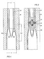
- a choke 20 is inserted into the well testing pipe 10 until the choke 20 is disposed adjacent the constriction 10a of the well testing pipe 10.
- the presence of choke 20 adjacent constriction 10a causes the well fluid flowing in an annulus region 10b of pipe 10, between the choke 20 and an inner wall of the constriction 10a, to flow more rapidly.
- Flowrate through a pipe is proportional to the velocity of the fluid flowing in the pipe and the cross-sectional area of the pipe. If the area available to the flow is decreased, the fluid velocity must increase. An increase in fluid velocity results in a decrease in pressure.
- a differential pressure gauge were connected to pipe 10 of figure 1b so as to measure the differential pressure "delta P" in figure 1b, the decrease in pressure, experienced when the choke 20 is inserted in pipe 10, would convert an otherwise small change in pressure into a larger change in pressure, the larger change in pressure being easily detectable by the differential pressure gauge measuring the "delta P" of figure 1b.
- the choke 20 of figure 2 may be lowered into the well testing pipe 10 on a wireline after the well testing pipe is already disposed in a borehole. Alternatively, after the well testing pipe is already disposed in a borehole, the choke 20 of figure 2 may be connected to coiled tubing at the well head, transported into the well testing pipe when connected to the coiled tubing, and positioned into place within the well testing pipe in response to manipulation of the coiled tubing.
- the choke 20 of figure 2 is illustrated, the choke 20 further including a latch mechanism 22 which mates with an interior groove 24 formed in the interior wall of the well testing pipe 10.
- the latch mechanism 22 is spring biased by a spring 26 which biases the latch 22 into engagement with the interior groove 24, when the choke 20 is disposed appropriately within the well testing pipe 10.
- a pull upwardly on the choke 20 moves the latch 22 radially inward and out of engagement with the interior groove 24.
- the choke 20 may be removed from its position within the well testing pipe 10.
- the choke 20 includes an fluid-dynamically shaped pointed tip portion 20a, the fluid-dynamically shaped tip portion 20a enabling the well fluid to easily pass into the annulus region 10b between the choke 20 and the well testing pipe 10 and more easily causing the corresponding decrease in the pressure of the well fluid in the annulus region 10b to occur.
- the decrease in pressure in the annulus region 10b converts the otherwise small change in pressure into the larger change in pressure, the larger change in pressure being more easily detectable by the differential pressure gauge measuring the change in pressure "Dpv" shown in figure 4.
Landscapes
- Geology (AREA)
- Life Sciences & Earth Sciences (AREA)
- Engineering & Computer Science (AREA)
- Physics & Mathematics (AREA)
- Mining & Mineral Resources (AREA)
- Fluid Mechanics (AREA)
- Environmental & Geological Engineering (AREA)
- General Life Sciences & Earth Sciences (AREA)
- Geochemistry & Mineralogy (AREA)
- Geophysics (AREA)
- General Physics & Mathematics (AREA)
- Measuring Fluid Pressure (AREA)
- Measuring Volume Flow (AREA)
Applications Claiming Priority (2)
| Application Number | Priority Date | Filing Date | Title |
|---|---|---|---|
| US07/515,907 US5174161A (en) | 1990-04-27 | 1990-04-27 | Wireline and coiled tubing retrievable choke for downhole flow measurement |
| US515907 | 1990-04-27 |
Publications (2)
| Publication Number | Publication Date |
|---|---|
| EP0454560A1 true EP0454560A1 (fr) | 1991-10-30 |
| EP0454560B1 EP0454560B1 (fr) | 1996-06-19 |
Family
ID=24053269
Family Applications (1)
| Application Number | Title | Priority Date | Filing Date |
|---|---|---|---|
| EP91401063A Expired - Lifetime EP0454560B1 (fr) | 1990-04-27 | 1991-04-23 | Etranglement mobile suspendu à un câble ou à un tube en spirale pour la mesure de débit dans un puits |
Country Status (3)
| Country | Link |
|---|---|
| US (1) | US5174161A (fr) |
| EP (1) | EP0454560B1 (fr) |
| DE (1) | DE69120343D1 (fr) |
Cited By (2)
| Publication number | Priority date | Publication date | Assignee | Title |
|---|---|---|---|---|
| WO2000042391A1 (fr) * | 1999-01-13 | 2000-07-20 | Expro North Sea Limited | Appareil perfectionne de surveillance de debit |
| WO2002035059A1 (fr) * | 2000-10-23 | 2002-05-02 | Halliburton Energy Services, Inc. | Capteurs de proprietes de fluide et procedes associes d'etalonnage de capteurs dans un puits souterrain |
Families Citing this family (4)
| Publication number | Priority date | Publication date | Assignee | Title |
|---|---|---|---|---|
| US5565631A (en) * | 1995-02-07 | 1996-10-15 | The Futurestar Corporation | Non-metallic flow meter float and method |
| US5691712A (en) * | 1995-07-25 | 1997-11-25 | Schlumberger Technology Corporation | Multiple wellbore tool apparatus including a plurality of microprocessor implemented wellbore tools for operating a corresponding plurality of included wellbore tools and acoustic transducers in response to stimulus signals and acoustic signals |
| US7793716B2 (en) * | 2006-04-21 | 2010-09-14 | Bj Services Company, U.S.A. | Apparatus and methods for limiting debris flow back into an underground base pipe of an injection well |
| US9574438B2 (en) | 2014-04-15 | 2017-02-21 | Baker Hughes Incorporated | Fluid velocity flow meter for a wellbore |
Citations (4)
| Publication number | Priority date | Publication date | Assignee | Title |
|---|---|---|---|---|
| US2042933A (en) * | 1935-11-04 | 1936-06-02 | Byron Jackson Co | Drilled-well pump and venturi meter |
| US3800870A (en) * | 1973-02-16 | 1974-04-02 | Texaco Inc | Formation testing tool |
| US4644800A (en) * | 1986-06-02 | 1987-02-24 | Combustion Engineering, Inc. | Annular venturi flow measuring device |
| EP0235032A2 (fr) * | 1986-02-21 | 1987-09-02 | Flopetrol Services, Inc. | Débimètre destiné notamment aux puits d'hydrocarbures |
Family Cites Families (30)
| Publication number | Priority date | Publication date | Assignee | Title |
|---|---|---|---|---|
| DE142503C (fr) * | ||||
| US2767580A (en) * | 1952-02-26 | 1956-10-23 | Bendix Aviat Corp | Fluid flow indicating apparatus |
| DE1104716B (de) * | 1958-01-15 | 1961-04-13 | Air Liquide | Verfahren und Vorrichtung zur Messung der Stroemungsmenge von Fluessigkeiten veraenderlicher Zusammensetzung |
| GB1089203A (en) * | 1963-08-15 | 1967-11-01 | Int Combustion Holdings Ltd | Improvements in or relating to fluid flow measuring devices |
| FR1453706A (fr) * | 1965-11-15 | 1966-06-03 | Débitmètre perfectionné pour liquides et gaz | |
| NL131453C (fr) * | 1965-12-14 | |||
| FR2101037B1 (fr) * | 1970-08-12 | 1973-04-27 | Schlumberger Prospection | |
| US3930742A (en) * | 1973-10-23 | 1976-01-06 | Howell Instruments, Inc. | Velocity probe for compressor surge control |
| DE2544559A1 (de) * | 1975-10-04 | 1977-04-07 | Bayer Ag | Verfahren und vorrichtung zum herstellen eines reaktionsgemisches fuer die produktion von schaumstoff |
| US4127332A (en) * | 1976-11-19 | 1978-11-28 | Daedalean Associates, Inc. | Homogenizing method and apparatus |
| FR2386021A1 (fr) * | 1977-03-31 | 1978-10-27 | Flopetrol Ste Auxil Product Pe | Procede et dispositif de determination du debit volumetrique de chaque phase d'un melange diphasique |
| GB1601699A (en) * | 1977-11-03 | 1981-11-04 | Gen Eng Radcliffe | Method and apparatus for dispersing a liquid additive throughout a plastics material |
| US4335965A (en) * | 1978-07-07 | 1982-06-22 | Dresser Industries, Inc. | Fiber-resin blending technique |
| US4231262A (en) * | 1979-03-28 | 1980-11-04 | The Babcock & Wilcox Company | System for measuring entrained solid flow |
| US4416610A (en) * | 1980-03-14 | 1983-11-22 | Hydroil, Inc. | Water-in-oil emulsifier and oil-burner boiler system incorporating such emulsifier |
| US4312234A (en) * | 1980-05-12 | 1982-01-26 | Alberta Oil Sands Technology And Research Authority | Two-phase flowmeter |
| GB2085597B (en) * | 1980-10-17 | 1985-01-30 | Redland Automation Ltd | Method and apparatus for detemining the mass flow of a fluid |
| US4430251A (en) * | 1981-09-29 | 1984-02-07 | Hoffert Manufacturing Co., Inc. | High energy emulsifier |
| US4441361A (en) * | 1981-10-02 | 1984-04-10 | Dresser Industries, Inc. | Method and apparatus for measurement of fluid density and flow rates in multi-phase flow regimes |
| DE3203986A1 (de) * | 1982-02-05 | 1983-08-18 | Robert Bosch Gmbh, 7000 Stuttgart | Verfahren zur messung des durchflusses eines mediums |
| DE3225449C2 (de) * | 1982-07-07 | 1988-09-29 | Klöckner Stahlforschung GmbH, 8458 Sulzbach-Rosenberg | Verfahren und Vorrichtung zum Messen und/oder Regeln des Massestromes von Feststoffteilchen |
| GB2128756B (en) * | 1982-10-04 | 1986-06-25 | Moore Barrett & Redwood | Measurement of two-phase or multi-phase fluid flow in pipes |
| CH657702A5 (en) * | 1982-10-26 | 1986-09-15 | Ciba Geigy Ag | Flow-rate measuring device for fluids, gases and vapours |
| US4528847A (en) * | 1983-10-04 | 1985-07-16 | D. Halmi And Associates, Inc. | Flow metering device with recessed pressure taps |
| US4576043A (en) * | 1984-05-17 | 1986-03-18 | Chevron Research Company | Methods for metering two-phase flow |
| US4604902A (en) * | 1984-10-24 | 1986-08-12 | Geoscience Ltd | Means and techniques useful in mass flowmeters for multiphase flows |
| DE3505833A1 (de) * | 1985-02-20 | 1986-08-21 | Krupp Koppers GmbH, 4300 Essen | Venturirohr |
| US4641535A (en) * | 1985-06-28 | 1987-02-10 | Nl Industries, Inc. | Flowmeter |
| US4856334A (en) * | 1987-05-26 | 1989-08-15 | Weyerhaeuser Company | Bond strength measurement of composite panel products |
| US4928764A (en) * | 1989-09-20 | 1990-05-29 | Halliburton Logging Services, Inc. | Wireline tool cable head overload apparatus |
-
1990
- 1990-04-27 US US07/515,907 patent/US5174161A/en not_active Expired - Lifetime
-
1991
- 1991-04-23 DE DE69120343T patent/DE69120343D1/de not_active Expired - Lifetime
- 1991-04-23 EP EP91401063A patent/EP0454560B1/fr not_active Expired - Lifetime
Patent Citations (4)
| Publication number | Priority date | Publication date | Assignee | Title |
|---|---|---|---|---|
| US2042933A (en) * | 1935-11-04 | 1936-06-02 | Byron Jackson Co | Drilled-well pump and venturi meter |
| US3800870A (en) * | 1973-02-16 | 1974-04-02 | Texaco Inc | Formation testing tool |
| EP0235032A2 (fr) * | 1986-02-21 | 1987-09-02 | Flopetrol Services, Inc. | Débimètre destiné notamment aux puits d'hydrocarbures |
| US4644800A (en) * | 1986-06-02 | 1987-02-24 | Combustion Engineering, Inc. | Annular venturi flow measuring device |
Cited By (5)
| Publication number | Priority date | Publication date | Assignee | Title |
|---|---|---|---|---|
| WO2000042391A1 (fr) * | 1999-01-13 | 2000-07-20 | Expro North Sea Limited | Appareil perfectionne de surveillance de debit |
| US6874374B2 (en) | 1999-01-13 | 2005-04-05 | Expro North Sea Limited | Flowmeter apparatus |
| WO2002035059A1 (fr) * | 2000-10-23 | 2002-05-02 | Halliburton Energy Services, Inc. | Capteurs de proprietes de fluide et procedes associes d'etalonnage de capteurs dans un puits souterrain |
| GB2390423A (en) * | 2000-10-23 | 2004-01-07 | Halliburton Energy Serv Inc | Fluid property sensors and associated methods of calibrating sensors in a subterranean well |
| GB2390423B (en) * | 2000-10-23 | 2004-12-29 | Halliburton Energy Serv Inc | Fluid property sensors and associated methods of calibrating sensors in a subterranean well |
Also Published As
| Publication number | Publication date |
|---|---|
| DE69120343D1 (de) | 1996-07-25 |
| US5174161A (en) | 1992-12-29 |
| EP0454560B1 (fr) | 1996-06-19 |
Similar Documents
| Publication | Publication Date | Title |
|---|---|---|
| Baxendell et al. | The calculation of pressure gradients in high-rate flowing wells | |
| US7107860B2 (en) | Flow meter using an expanded tube section and sensitive differential pressure measurement | |
| US5626192A (en) | Coiled tubing joint locator and methods | |
| US20080264182A1 (en) | Flow meter using sensitive differential pressure measurement | |
| EP1974121B1 (fr) | Procédé de suivi de propriétés d'un fluide | |
| US6253842B1 (en) | Wireless coiled tubing joint locator | |
| US6629564B1 (en) | Downhole flow meter | |
| CA2332241C (fr) | Localisateur de joints de raccord sans fil muni d'une bobine | |
| US20040086623A1 (en) | Storage stable pan release coating and cleaner | |
| US20190390543A1 (en) | Depth positioning using gamma-ray correlation and downhole parameter differential | |
| US8156801B2 (en) | Flow metering device | |
| US8230735B2 (en) | Method of dynamically correcting flow rate measurements | |
| US3895527A (en) | Method and apparatus for measuring pressure related parameters in a borehole | |
| Hagedorn et al. | The effect of liquid viscosity in two-phase vertical flow | |
| US5174161A (en) | Wireline and coiled tubing retrievable choke for downhole flow measurement | |
| GB2156880A (en) | Apparatus and methods for orienting devices in side pocket mandrels | |
| US20210381373A1 (en) | Systems and methods for transient testing of hydrocarbon wells | |
| US2158569A (en) | Formation tester | |
| US3985027A (en) | Controlled flow impedance in a pressure sensing system | |
| Millikan et al. | Bottom-hole pressures in oil wells | |
| US3874231A (en) | Diffusion barrier chamber for sperry sun permagage type pressure gage | |
| US2945952A (en) | Method and apparatus for locating producing zones in wells | |
| WO1999047895A1 (fr) | Debitmetre | |
| US4018088A (en) | Borehole pressure measurement apparatus having a high pressure float valve | |
| GB2121084A (en) | Well testing apparatus |
Legal Events
| Date | Code | Title | Description |
|---|---|---|---|
| PUAI | Public reference made under article 153(3) epc to a published international application that has entered the european phase |
Free format text: ORIGINAL CODE: 0009012 |
|
| AK | Designated contracting states |
Kind code of ref document: A1 Designated state(s): DE FR GB IT NL |
|
| 17P | Request for examination filed |
Effective date: 19920415 |
|
| 17Q | First examination report despatched |
Effective date: 19940208 |
|
| GRAH | Despatch of communication of intention to grant a patent |
Free format text: ORIGINAL CODE: EPIDOS IGRA |
|
| GRAA | (expected) grant |
Free format text: ORIGINAL CODE: 0009210 |
|
| AK | Designated contracting states |
Kind code of ref document: B1 Designated state(s): DE FR GB IT NL |
|
| PG25 | Lapsed in a contracting state [announced via postgrant information from national office to epo] |
Ref country code: IT Free format text: LAPSE BECAUSE OF FAILURE TO SUBMIT A TRANSLATION OF THE DESCRIPTION OR TO PAY THE FEE WITHIN THE PRE;WARNING: LAPSES OF ITALIAN PATENTS WITH EFFECTIVE DATE BEFORE 2007 MAY HAVE OCCURRED AT ANY TIME BEFORE 2007. THE CORRECT EFFECTIVE DATE MAY BE DIFFERENT FROM THE ONE RECORDED.SCRIBED TIME-LIMIT Effective date: 19960619 |
|
| REF | Corresponds to: |
Ref document number: 69120343 Country of ref document: DE Date of ref document: 19960725 |
|
| ET | Fr: translation filed | ||
| PG25 | Lapsed in a contracting state [announced via postgrant information from national office to epo] |
Ref country code: DE Effective date: 19960920 |
|
| PLBE | No opposition filed within time limit |
Free format text: ORIGINAL CODE: 0009261 |
|
| STAA | Information on the status of an ep patent application or granted ep patent |
Free format text: STATUS: NO OPPOSITION FILED WITHIN TIME LIMIT |
|
| 26N | No opposition filed | ||
| REG | Reference to a national code |
Ref country code: GB Ref legal event code: IF02 |
|
| PGFP | Annual fee paid to national office [announced via postgrant information from national office to epo] |
Ref country code: NL Payment date: 20020426 Year of fee payment: 12 |
|
| PG25 | Lapsed in a contracting state [announced via postgrant information from national office to epo] |
Ref country code: NL Free format text: LAPSE BECAUSE OF NON-PAYMENT OF DUE FEES Effective date: 20031101 |
|
| NLV4 | Nl: lapsed or anulled due to non-payment of the annual fee |
Effective date: 20031101 |
|
| PGFP | Annual fee paid to national office [announced via postgrant information from national office to epo] |
Ref country code: GB Payment date: 20070418 Year of fee payment: 17 |
|
| PGFP | Annual fee paid to national office [announced via postgrant information from national office to epo] |
Ref country code: FR Payment date: 20070411 Year of fee payment: 17 |
|
| GBPC | Gb: european patent ceased through non-payment of renewal fee |
Effective date: 20080423 |
|
| REG | Reference to a national code |
Ref country code: FR Ref legal event code: ST Effective date: 20081231 |
|
| PG25 | Lapsed in a contracting state [announced via postgrant information from national office to epo] |
Ref country code: FR Free format text: LAPSE BECAUSE OF NON-PAYMENT OF DUE FEES Effective date: 20080430 |
|
| PG25 | Lapsed in a contracting state [announced via postgrant information from national office to epo] |
Ref country code: GB Free format text: LAPSE BECAUSE OF NON-PAYMENT OF DUE FEES Effective date: 20080423 |