EP0454561B1 - Vorrichtung zum Kontrollieren der Kontinuität eines verbindungsabdichtenden Klebestranges - Google Patents
Vorrichtung zum Kontrollieren der Kontinuität eines verbindungsabdichtenden Klebestranges Download PDFInfo
- Publication number
- EP0454561B1 EP0454561B1 EP19910401064 EP91401064A EP0454561B1 EP 0454561 B1 EP0454561 B1 EP 0454561B1 EP 19910401064 EP19910401064 EP 19910401064 EP 91401064 A EP91401064 A EP 91401064A EP 0454561 B1 EP0454561 B1 EP 0454561B1
- Authority
- EP
- European Patent Office
- Prior art keywords
- rotor
- detection zone
- stator
- glue
- monitoring means
- Prior art date
- Legal status (The legal status is an assumption and is not a legal conclusion. Google has not performed a legal analysis and makes no representation as to the accuracy of the status listed.)
- Expired - Lifetime
Links
- 239000000853 adhesive Substances 0.000 title description 2
- 230000001070 adhesive effect Effects 0.000 title description 2
- 238000001514 detection method Methods 0.000 claims description 20
- 239000003292 glue Substances 0.000 claims description 10
- 230000005540 biological transmission Effects 0.000 claims description 8
- 230000003287 optical effect Effects 0.000 claims description 7
- 238000000151 deposition Methods 0.000 claims description 3
- 238000012544 monitoring process Methods 0.000 claims 6
- 230000001419 dependent effect Effects 0.000 claims 1
- 239000000835 fiber Substances 0.000 description 11
- 239000011324 bead Substances 0.000 description 7
- 239000013307 optical fiber Substances 0.000 description 2
- XLYOFNOQVPJJNP-UHFFFAOYSA-N water Substances O XLYOFNOQVPJJNP-UHFFFAOYSA-N 0.000 description 2
- 238000002485 combustion reaction Methods 0.000 description 1
- 230000002950 deficient Effects 0.000 description 1
- 238000006073 displacement reaction Methods 0.000 description 1
- 235000011837 pasties Nutrition 0.000 description 1
- 239000011347 resin Substances 0.000 description 1
- 229920005989 resin Polymers 0.000 description 1
Images

Classifications
-
- G—PHYSICS
- G01—MEASURING; TESTING
- G01N—INVESTIGATING OR ANALYSING MATERIALS BY DETERMINING THEIR CHEMICAL OR PHYSICAL PROPERTIES
- G01N21/00—Investigating or analysing materials by the use of optical means, i.e. using sub-millimetre waves, infrared, visible or ultraviolet light
- G01N21/17—Systems in which incident light is modified in accordance with the properties of the material investigated
- G01N21/55—Specular reflectivity
-
- G—PHYSICS
- G01—MEASURING; TESTING
- G01N—INVESTIGATING OR ANALYSING MATERIALS BY DETERMINING THEIR CHEMICAL OR PHYSICAL PROPERTIES
- G01N21/00—Investigating or analysing materials by the use of optical means, i.e. using sub-millimetre waves, infrared, visible or ultraviolet light
- G01N21/17—Systems in which incident light is modified in accordance with the properties of the material investigated
- G01N21/47—Scattering, i.e. diffuse reflection
- G01N21/4738—Diffuse reflection, e.g. also for testing fluids, fibrous materials
- G01N21/474—Details of optical heads therefor, e.g. using optical fibres
- G01N2021/4742—Details of optical heads therefor, e.g. using optical fibres comprising optical fibres
- G01N2021/4745—Fused bundle, i.e. for backscatter
-
- G—PHYSICS
- G01—MEASURING; TESTING
- G01N—INVESTIGATING OR ANALYSING MATERIALS BY DETERMINING THEIR CHEMICAL OR PHYSICAL PROPERTIES
- G01N21/00—Investigating or analysing materials by the use of optical means, i.e. using sub-millimetre waves, infrared, visible or ultraviolet light
- G01N21/84—Systems specially adapted for particular applications
- G01N21/85—Investigating moving fluids or granular solids
- G01N2021/8592—Grain or other flowing solid samples
Definitions
- the present invention relates to a device for checking the continuity of a bead of adhesive forming a joint, this type of joint being used to ensure a seal between two flat faces, for example between two housings of an internal combustion engine.
- This cord must therefore have no discontinuity, as this would cause a leak, for example an oil leak for a cord installed between the two engine casings, or a water leak for a cord installed between the engine block and the water pump.
- This additional position occupies a significant floor space and represents a significant investment.
- the present invention aims to eliminate these drawbacks. It makes it possible to eliminate the additional station by ensuring a control of the continuity of the cord at the level of the depositing station, and it can also allow an automatic retouching of the cord, by a slight backward movement of the depositing nozzle.
- the present invention relates to a device for controlling a bead of glue forming a seal, the glue being delivered to the end of a nozzle.
- this control device comprises a light emission source, a detection zone located near the outlet of the nozzle, a light reception cell, and transmission means connecting the emission source to the detection zone, and the detection zone at the receiving cell, the level of reflection being a function of the continuity of the cord.
- this device allows rotation of the detection zone, in order to follow a bead with a curved trajectory.
- the device comprises a stator and a rotor carrying the detection zone and rotating around an axis coincident with that of the nozzle.
- the transmission means consist of four networks of optical fibers passing through the stator and the rotor, an optical rotary joint being thus formed at the stator / rotor junction.
- the detection zone C2 situated at the base of the cord has an angle A2 of 180 with respect to a reference parallel to the axis X.
- the detection zone C1 situated at the base of the cord has an angle A1 of 90 °.
- the cord has therefore rotated 90 ° and the detection zone also, because this detection zone, mounted on a rotor 20 of the control device, follows the cord continuously.
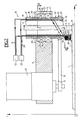
- FIG. 2 shows in a plane X, Z, the cord 1 deposited by the nozzle 2 through its central orifice 3, and the control device 10.
- This device 10 comprises a frame 11 terminated at one end by a cap 12 held by two screws (not shown), a micro geared motor 13 at the end of which is mounted a pulley 14, a stator 16 and a rotor 20 driven in rotation.
- the rotor 20 comprises a pulley 22 connected to the pulley 14 of the micro-geared motor 13 by a belt 15, the rotor rotating on two ball bearings 21 integral with the frame 11.
- This control device also includes a light emission source 27, a detection area C, a reception cell 32 and transmission means made up of four optical fiber networks 28, 29, 30, 31, two emission networks 28, 29 and two reception networks 30, 31.
- a rotating optical joint is formed by ensuring a distribution of all the fibers of each network on all the periphery of the stator and the rotor.
- This stator 16 therefore consists of three concentric tubes 17, 18, 19 and the rotor 20 also consists of three concentric tubes 23, 24, 25.
- the fibers of the transmission network 28 are inserted, around the entire periphery, the fibers of the transmission network 28, and between the tubes 18 and 17 of the stator are inserted, around the entire periphery, the fibers of the reception network 31.
- the fibers of the transmission network 29 are inserted, around the entire periphery, the fibers of the reception network 30, as can be seen in the right half-section of FIG. 3.
- the four fiber networks are embedded in a resin which respectively stiffens the stator on the one hand and the rotor on the other.
- the detection zone C comprises a tube 26 clearly visible on the left half-section of FIG. 3.
- This tube 26 is integral with an extension 25 ′ of the internal tube 25 of the rotor 20, and this tube 26 contains the two networks of fibers 29 and 30. It is therefore understood that the fibers of the networks 28, 31 are concentrated at the level of the source 27 and of the cell 28, then they gradually expand until they occupy the entire periphery of the rotary joint formed at the stator / rotor junction, while the fibers of the networks 29, 30 are expanded over the entire periphery of the rotary joint, then they gradually regroup until they fill the inside of the tube 26 of the detection zone C.
- the emission fibers and the reception fibers can be randomly mixed, or arranged in a uniform and alternating manner in order to ensure better reflection.
- Such a control device operates in the following manner: the nozzle follows a determined, programmed trajectory, and the control device follows this same trajectory, since the frame 11 of the device 20 is integral with the frame which carries the nozzle.
- zone C is positioned in the axis of displacement of the nozzle to immediately check the bead and, with each variation of trajectory of the nozzle, the detection zone will be immediately repositioned in the axis of the new trajectory by a rotation of the rotor controlled by this trajectory. The cord will thus be continuously checked, and each discontinuity is immediately detected. Manual retouching is then performed, or better still, automatic retouching ensured by a slight recoil from the nozzle.
Landscapes
- Immunology (AREA)
- Pathology (AREA)
- Life Sciences & Earth Sciences (AREA)
- Chemical & Material Sciences (AREA)
- Analytical Chemistry (AREA)
- Biochemistry (AREA)
- Health & Medical Sciences (AREA)
- General Health & Medical Sciences (AREA)
- Physics & Mathematics (AREA)
- General Physics & Mathematics (AREA)
- Coating Apparatus (AREA)
- Braiding, Manufacturing Of Bobbin-Net Or Lace, And Manufacturing Of Nets By Knotting (AREA)
- Investigating Materials By The Use Of Optical Means Adapted For Particular Applications (AREA)
- Treatment Of Fiber Materials (AREA)
- Tyre Moulding (AREA)
- Spray Control Apparatus (AREA)
Claims (8)
Applications Claiming Priority (2)
| Application Number | Priority Date | Filing Date | Title |
|---|---|---|---|
| FR9005208 | 1990-04-24 | ||
| FR9005208A FR2661247B1 (fr) | 1990-04-24 | 1990-04-24 | Dispositif permettant le controle de la continuite d'un cordon de colle formant joint. |
Publications (3)
| Publication Number | Publication Date |
|---|---|
| EP0454561A1 EP0454561A1 (de) | 1991-10-30 |
| EP0454561B1 true EP0454561B1 (de) | 1994-09-14 |
| EP0454561B2 EP0454561B2 (de) | 1997-07-23 |
Family
ID=9396030
Family Applications (1)
| Application Number | Title | Priority Date | Filing Date |
|---|---|---|---|
| EP19910401064 Expired - Lifetime EP0454561B2 (de) | 1990-04-24 | 1991-04-23 | Vorrichtung zum Kontrollieren der Kontinuität eines verbindungsabdichtenden Klebestranges |
Country Status (4)
| Country | Link |
|---|---|
| EP (1) | EP0454561B2 (de) |
| DE (1) | DE69103951T3 (de) |
| ES (1) | ES2059076T5 (de) |
| FR (1) | FR2661247B1 (de) |
Families Citing this family (8)
| Publication number | Priority date | Publication date | Assignee | Title |
|---|---|---|---|---|
| EP0599126B1 (de) * | 1992-11-20 | 1998-04-15 | Nordson Corporation | Methode zum Überwachen und/oder abgeben von Material auf ein Substrat |
| FR2703784B1 (fr) * | 1993-04-05 | 1995-07-07 | Renault Automation | Procédé et dispositif de contrôle de la continuité d'un cordon de colle. |
| FR2703783B1 (fr) * | 1993-04-05 | 1995-05-19 | Renault Automation | Procédé de contrôle de la continuité d'un cordon de produit déposé sur une surface. |
| FR2727518A1 (fr) * | 1994-11-28 | 1996-05-31 | Renault Automation | Dispositif de controle de la qualite et de la continuite d'un cordon de produit depose sur une surface |
| US5868840A (en) * | 1996-12-30 | 1999-02-09 | The University Of Northern Iowa Foundation | Paint gun incorporating a laser device |
| DE10048749A1 (de) | 2000-09-29 | 2002-04-11 | Josef Schucker | Anordnung zum Aufbringen von Klebstoff auf ein Werkstück |
| DE10252340B4 (de) * | 2002-11-05 | 2013-09-26 | Quiss Gmbh | Vorrichtung zum Erkennen einer auf einem Substrat aufzubringenden Struktur sowie geeignete Verfahren hierfür |
| DE10361018C9 (de) | 2003-12-23 | 2021-03-04 | QUISS Qualitäts-Inspektionssysteme und Service GmbH | Verfahren zum Erkennen einer auf einem Substrat aufzubringenden Struktur mit mehreren Kameras sowie eine Vorrichtung hierfür |
Family Cites Families (5)
| Publication number | Priority date | Publication date | Assignee | Title |
|---|---|---|---|---|
| US4037724A (en) * | 1975-05-20 | 1977-07-26 | Firma Up Geratebau-Und Vertriebs Gmbh | Method of and apparatus for measuring defects in sealings |
| JPS576307A (en) * | 1980-06-13 | 1982-01-13 | Toyota Central Res & Dev Lab Inc | Method and apparatus of surface failure inspection of circular member |
| NL8701093A (nl) * | 1987-05-08 | 1988-12-01 | Friesland Condensfab | Inrichting voor het detecteren van onvolkomenheden in de afdichtingsrubber in de dekselrand van felsbussen en van deze inrichting afkomstige deksels. |
| US4876455A (en) * | 1988-02-25 | 1989-10-24 | Westinghouse Electric Corp. | Fiber optic solder joint inspection system |
| US4873432A (en) * | 1988-08-25 | 1989-10-10 | American National Can Company | Compound application detector |
-
1990
- 1990-04-24 FR FR9005208A patent/FR2661247B1/fr not_active Expired - Lifetime
-
1991
- 1991-04-23 ES ES91401064T patent/ES2059076T5/es not_active Expired - Lifetime
- 1991-04-23 EP EP19910401064 patent/EP0454561B2/de not_active Expired - Lifetime
- 1991-04-23 DE DE1991603951 patent/DE69103951T3/de not_active Expired - Fee Related
Also Published As
| Publication number | Publication date |
|---|---|
| FR2661247A1 (fr) | 1991-10-25 |
| DE69103951T2 (de) | 1995-05-04 |
| ES2059076T5 (es) | 1997-10-16 |
| DE69103951T3 (de) | 1997-10-16 |
| DE69103951D1 (de) | 1994-10-20 |
| EP0454561B2 (de) | 1997-07-23 |
| EP0454561A1 (de) | 1991-10-30 |
| FR2661247B1 (fr) | 1995-11-03 |
| ES2059076T3 (es) | 1994-11-01 |
Similar Documents
| Publication | Publication Date | Title |
|---|---|---|
| EP0454561B1 (de) | Vorrichtung zum Kontrollieren der Kontinuität eines verbindungsabdichtenden Klebestranges | |
| CA2824382C (fr) | Dispositif de recherche de defauts sur des pieces par endoscopie | |
| EP0567392B1 (de) | Ringförmige Bürstendichtung | |
| EP0484229B1 (de) | Probe mit drehendem Steuerkopf zum Prüfen gebogener Röhren | |
| EP0383671B1 (de) | Hindernisdetektor mit einem verbesserten Verbindungszusammenbau | |
| EP0282389B1 (de) | Elektrische Verbindungsvorrichtung zwischen zwei Bündeln von leitenden Drähten und mit dieser Vorrichtung ausgestattetes Kraftfahrzeug | |
| KR930017254A (ko) | 통신 케이블용 복원 키트 | |
| EP1404996A1 (de) | Steuerventil für kühlsystem eines motors | |
| EP0469948A1 (de) | Einrichtung zur Bestimmung des Abnutzungszustandes von Fahrzeugluftreifen | |
| WO2003054438A1 (fr) | Gaine de protection refermable par recouvrement et utilisation de cette gaine | |
| EP0061124A1 (de) | Schrittfolgegerät für schraubenförmige Rinnen | |
| FR3065898A1 (fr) | Articulation pour bras robotise | |
| FR2743110A1 (fr) | Divergent deployable de propulseur | |
| FR2746039A1 (fr) | Procede et dispositif de nettoyage de conduits par robot telecommande | |
| WO2018091814A1 (fr) | Machine et procédé pour la pose simultanée et en hélice de câbles sur la surface externe d'un élément unitaire de conduite de transport de fluides | |
| FR2563627A1 (fr) | Procede et appareil pour l'eclairage en retour de connecteurs optiques | |
| FR2716512A1 (fr) | Dispositif à volant, comportant un joint à labyrinthe, dans une transmission de véhicule automobile . | |
| FR2670303A1 (fr) | Tete d'eclatement pour cables a fibres optiques. | |
| EP0497654B1 (de) | Verfahren zum Einfetten eines erdverlegten Rohrs mit gleichzeitigem Einblasen eines Kabels in dieses Rohr | |
| FR2684343A1 (fr) | Dispositif de projection d'un liquide de nettoyage integre a un balai d'essui-glace, en particulier pour vehicule automobile. | |
| FR2690635A1 (fr) | Dispositif de protection pour un appareillage optique, et système optique comprenant un tel dispositif. | |
| EP0463924B1 (de) | Verfahren zum Einziehen eines Kabels in ein Rohr und Vorrichtung zur Durchführung des Verfahens | |
| FR3139554A1 (fr) | Ensemble de propulsion comprenant un système de transmission, plusieurs moteurs électriques et au moins un système d’accouplement déporté, aéronef comprenant au moins un tel ensemble de propulsion | |
| FR2864713A1 (fr) | Raccordement de presse etoupe orientable pour faisceau de cables electriques | |
| FR2655071A1 (fr) | Dispositif de nettoiement de chaussee a encombrement reduit, notamment pour engin mobile. |
Legal Events
| Date | Code | Title | Description |
|---|---|---|---|
| PUAI | Public reference made under article 153(3) epc to a published international application that has entered the european phase |
Free format text: ORIGINAL CODE: 0009012 |
|
| AK | Designated contracting states |
Kind code of ref document: A1 Designated state(s): BE DE ES GB IT |
|
| 17P | Request for examination filed |
Effective date: 19920403 |
|
| 17Q | First examination report despatched |
Effective date: 19930714 |
|
| GRAA | (expected) grant |
Free format text: ORIGINAL CODE: 0009210 |
|
| AK | Designated contracting states |
Kind code of ref document: B1 Designated state(s): BE DE ES GB IT |
|
| ITF | It: translation for a ep patent filed | ||
| GBT | Gb: translation of ep patent filed (gb section 77(6)(a)/1977) |
Effective date: 19940915 |
|
| REF | Corresponds to: |
Ref document number: 69103951 Country of ref document: DE Date of ref document: 19941020 |
|
| REG | Reference to a national code |
Ref country code: ES Ref legal event code: FG2A Ref document number: 2059076 Country of ref document: ES Kind code of ref document: T3 |
|
| PLBI | Opposition filed |
Free format text: ORIGINAL CODE: 0009260 |
|
| 26 | Opposition filed |
Opponent name: BAYERISCHE MOTOREN WERKE AKTIENGESELLSCHAFT Effective date: 19950522 |
|
| PLAW | Interlocutory decision in opposition |
Free format text: ORIGINAL CODE: EPIDOS IDOP |
|
| PLAW | Interlocutory decision in opposition |
Free format text: ORIGINAL CODE: EPIDOS IDOP |
|
| PUAH | Patent maintained in amended form |
Free format text: ORIGINAL CODE: 0009272 |
|
| STAA | Information on the status of an ep patent application or granted ep patent |
Free format text: STATUS: PATENT MAINTAINED AS AMENDED |
|
| 27A | Patent maintained in amended form |
Effective date: 19970723 |
|
| AK | Designated contracting states |
Kind code of ref document: B2 Designated state(s): BE DE ES GB IT |
|
| ITF | It: translation for a ep patent filed | ||
| REG | Reference to a national code |
Ref country code: ES Ref legal event code: DC2A Kind code of ref document: T5 Effective date: 19970912 |
|
| GBTA | Gb: translation of amended ep patent filed (gb section 77(6)(b)/1977) | ||
| REG | Reference to a national code |
Ref country code: GB Ref legal event code: IF02 |
|
| PGFP | Annual fee paid to national office [announced via postgrant information from national office to epo] |
Ref country code: ES Payment date: 20020418 Year of fee payment: 12 |
|
| PGFP | Annual fee paid to national office [announced via postgrant information from national office to epo] |
Ref country code: GB Payment date: 20030326 Year of fee payment: 13 |
|
| PGFP | Annual fee paid to national office [announced via postgrant information from national office to epo] |
Ref country code: DE Payment date: 20030331 Year of fee payment: 13 |
|
| PGFP | Annual fee paid to national office [announced via postgrant information from national office to epo] |
Ref country code: BE Payment date: 20030423 Year of fee payment: 13 |
|
| PG25 | Lapsed in a contracting state [announced via postgrant information from national office to epo] |
Ref country code: GB Free format text: LAPSE BECAUSE OF NON-PAYMENT OF DUE FEES Effective date: 20040423 |
|
| PG25 | Lapsed in a contracting state [announced via postgrant information from national office to epo] |
Ref country code: ES Free format text: LAPSE BECAUSE OF NON-PAYMENT OF DUE FEES Effective date: 20040424 |
|
| PG25 | Lapsed in a contracting state [announced via postgrant information from national office to epo] |
Ref country code: BE Free format text: LAPSE BECAUSE OF NON-PAYMENT OF DUE FEES Effective date: 20040430 |
|
| BERE | Be: lapsed |
Owner name: *RENAULT AUTOMATION Effective date: 20040430 |
|
| PG25 | Lapsed in a contracting state [announced via postgrant information from national office to epo] |
Ref country code: DE Free format text: LAPSE BECAUSE OF NON-PAYMENT OF DUE FEES Effective date: 20041103 |
|
| GBPC | Gb: european patent ceased through non-payment of renewal fee |
Effective date: 20040423 |
|
| PG25 | Lapsed in a contracting state [announced via postgrant information from national office to epo] |
Ref country code: IT Free format text: LAPSE BECAUSE OF NON-PAYMENT OF DUE FEES;WARNING: LAPSES OF ITALIAN PATENTS WITH EFFECTIVE DATE BEFORE 2007 MAY HAVE OCCURRED AT ANY TIME BEFORE 2007. THE CORRECT EFFECTIVE DATE MAY BE DIFFERENT FROM THE ONE RECORDED. Effective date: 20050423 |
|
| REG | Reference to a national code |
Ref country code: ES Ref legal event code: FD2A Effective date: 20040424 |